Week -2
Modeling of a DoorBell(1) and controlling the fan motor of a heater(2) using Simulink
AIM :
1. To make a Simulink model of doorbell using a solenoid block. Condition - the switch is closed for 2 seconds and then released.
2. To make a Simulink model that uses a thermistor to sense the temperature of a heater and turns on/off the fan as per the required conditions. Condition - Fan turns ON above 25° C, OFF otherwise.
Part 1:
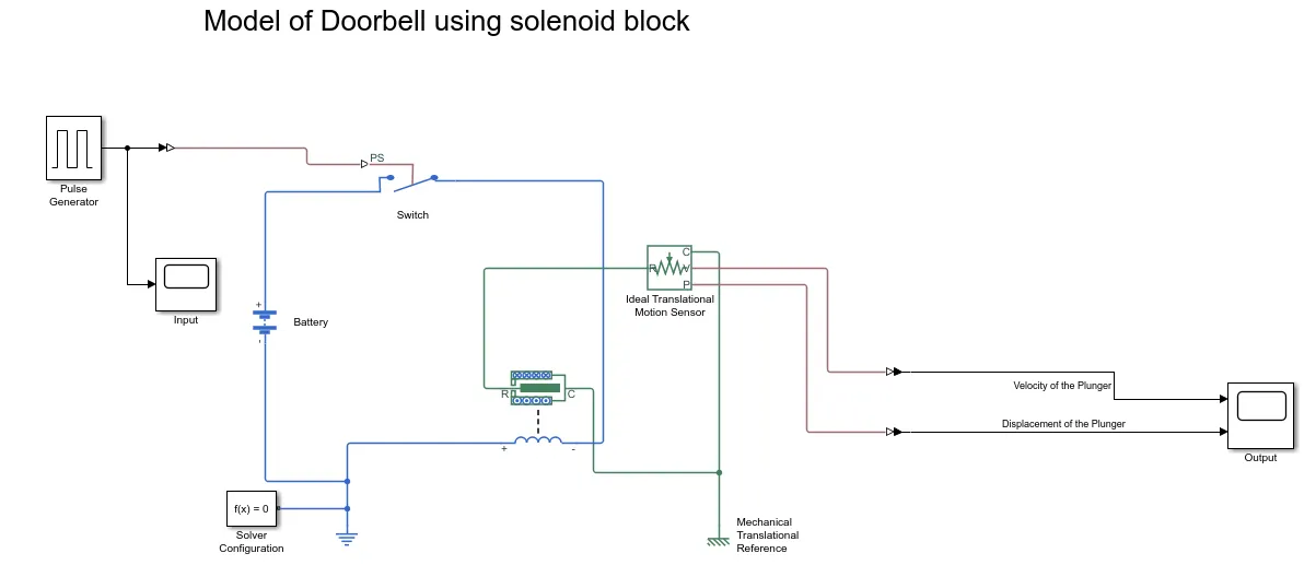
The solenoid blockset is added to the blank model screen. A solenoid is a generic term for a coil of wire used as an electromagnet. The device creates a magnetic field from electric current and uses the magnetic field to create linear motion. Common applications of solenoids are to power a switch, like a starter in an automobile, or a valve, such as in a sprinkler system. A battery is connected to a voltage supply. A switch is placed in between the battery and the solenoid to cater for the provided conditions. Here, an SPST switch is used. There are different types of switches available as per requirements. A separate input signal is provided for the closing/opening of the switch. The switch gets closed if the external control signal is greater than the threshold value of the switch.
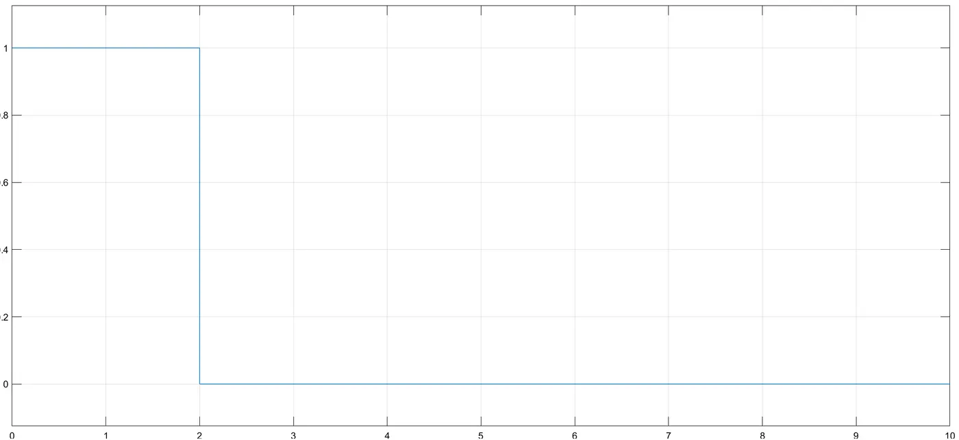
The external signal for the switch is provided with a Pulse Generator block with a period 4 sec and pulse width = 50% of the time period. To sense the movement of the plunger, an Ideal Translational motion sensor is connected to it. Now, to observe this movement over the simulation period, a Scope block is connected. Signal converters such as Simulink-PS and PS-Simulink convertors are provided for proper connections. Proper reference blocks are connected along with solver configurations for proper evaluation of the mathematical model.
Model:
Working:
A battery is connected to a switch and solenoid. An electric reference is needed for the batterySolve configuration is also needed to specify the type of mechanical reference that is also needed for the Solenoid.
A 'pulse generator' block is used a generate a pulse for when the switch has to be pressed to close the circuit with a time of 2-seconds
Simulink-PS converter is used to send a signal to the physical system since 'pulse generator' is a Simulink system when the circuit closes, the solenoid moves from port 'C to R' and the movement the sensed by the an ''Ideal Transitional Motion Sensor" to provide output
The output graph is plotted by the 'Scope' block which is obtained from the sensor with Ps-Simulink convertor.
Input Signal:
Output Graphs:
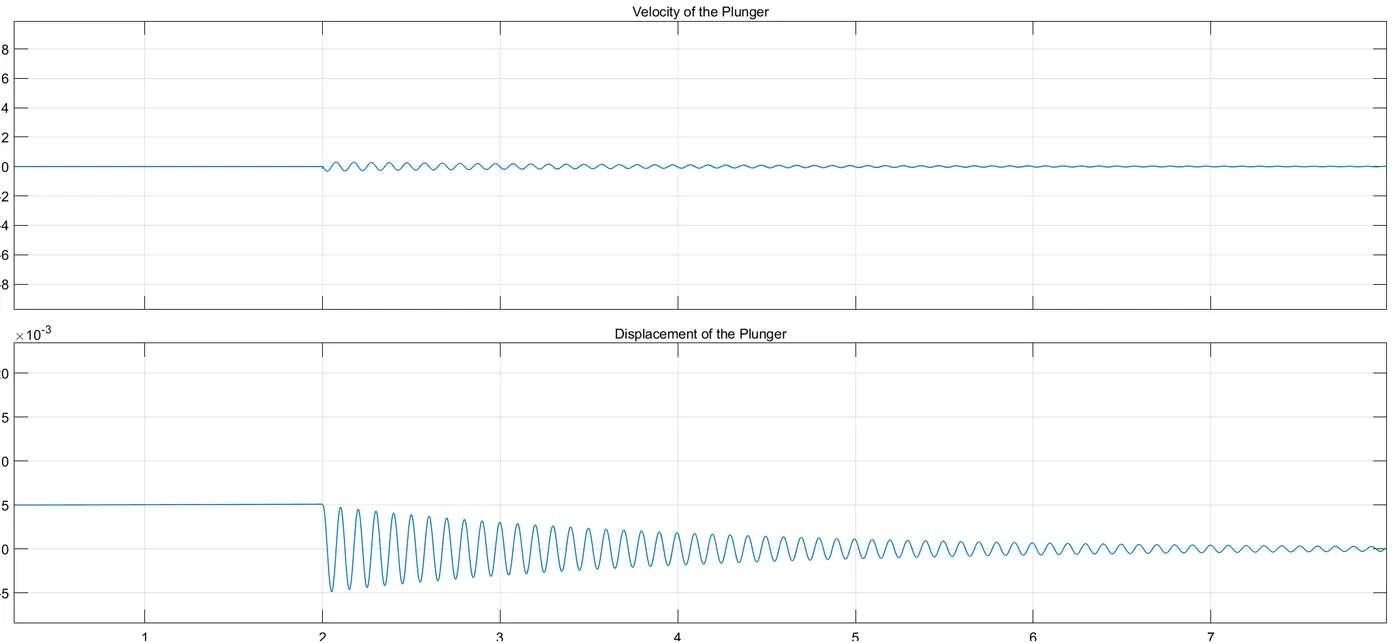
The damping of the damper and even the mass of the plunger of the Solenoid can be changed to control the displacement and velocity of the plunger.
Part 2: Using a thermistor to sense the temperature of a heater & turn on or turn off the fan motor
Theory:
Thermistor:
A thermistor (or thermal resistor) is defined as a type of resistor whose electrical resistance varies with changes in temperature. Although all resistors%E2%80%99 resistance will fluctuate slightly with temperature, a thermistor is particularly sensitive to temperature changes.
There are two types of thermistors:-
Negative Temperature Coefficient (NTC) Thermistor and
Positive Temperature Coefficient (PTC) Thermistor
The NTC thermistor block is added to the blank model screen. A thermistor is a type of resistor whose resistance is dependent on temperature. With NTC thermistors, resistance decreases as temperature rises. An NTC is commonly used as a temperature sensor, or in series with a circuit as an inrush current limiter. With PTC thermistors, resistance increases as temperature rises. PTC thermistors are commonly installed in series with a circuit and used to protect against overcurrent conditions, as resettable fuses. The required conditional input is generated using a Signal Builder block.
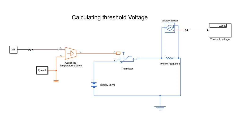
Calculating the threshold voltage for NTC thermistor using a constant block first of 25 degrees Celcius (298K) threshold temperature:
Model:
Working:
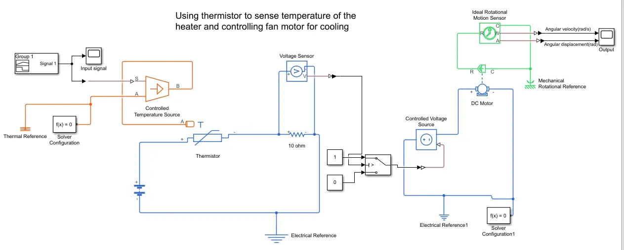
An NTC thermistor is used to sense the temperature change. In an NTC thermistor if the temperature increases the resistance decreases. A reference resistor is used in series with the thermistor so as to measure the voltage drop change as temperature changes. The voltage sensor placed across the reference resistor sense voltage and it is given to a logic circuit based on the fan motor turns on/off criteria provided (here fan should turn on if temp>25'C) operates the dc motor switch. A rotational sensor placed in the motor measures the fan operating velocity
Input signal using signal builder for 50 seconds:
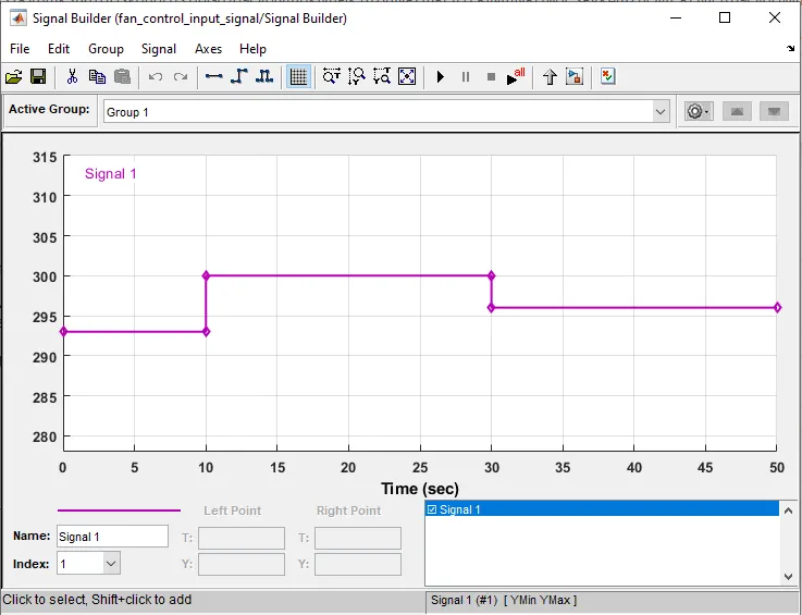
In this model, we are providing a signal built input to a controlled temperature source. In signal builder according to the questions we have provided the input i.e. 0 to 10 secs 20 Celcius, 10 to 30 secs 27 Celcius & 30 to 50 secs 23 Celcius. Here in the signal builder, we have given the temperature values as Kelvin because the thermistor takes values only in Kelvin.
Output Graphs:
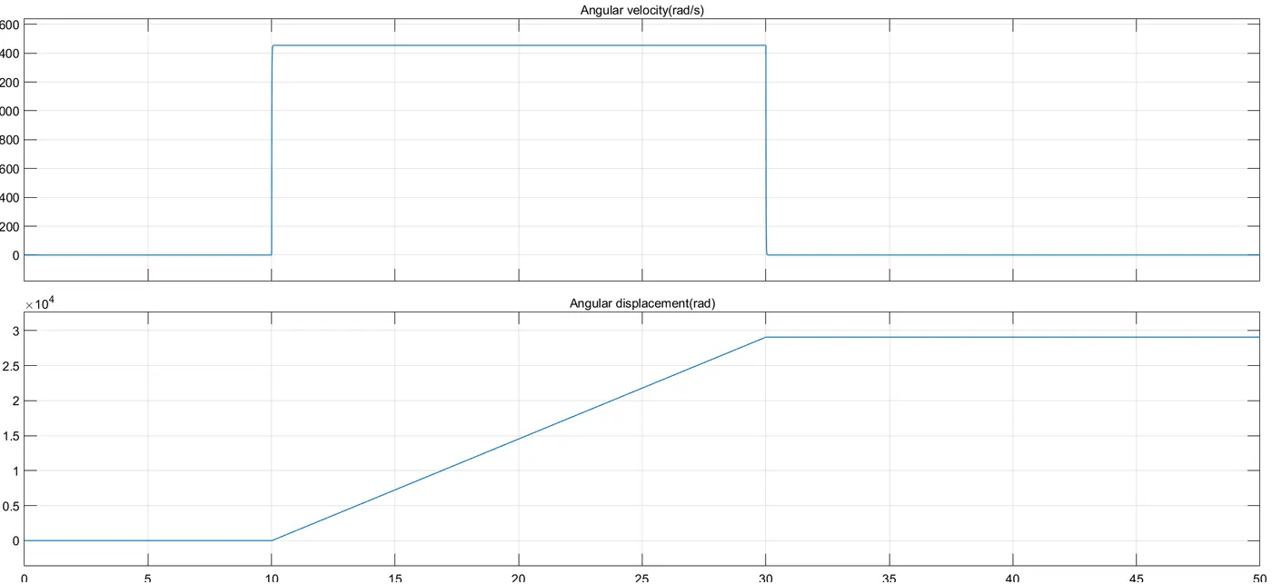
For 0-10 secs fan is in OFF condition because the temperature is 293K which is below 298K. After 10 secs the temperature goes to 300K, so the fan motor will turn ON because the temperature exceeds 298K. After 30 secs fan motor will turn OFF because the temperature goes to 296K which is below 298K.
Conclusion:
1) We have prepared a Simulink model of Doorbell using a solenoid block and we have also created a situation where the switch is closed for 2 seconds and then released.
2) We have prepared a Simulink model of Thermistor to sense the temperature of a heater & turn on or turn off the fan motor. We also observed that the fan motor is turned ON when the temperature is above 25 degrees Celsius and turned OFF when the temperature is below 25 degrees Celcius.