Week - 4
AIM : To find the Washing machine complete proceses given sequence, and
required speed to gear shifting to display on gear number to spcified
block.
OBJECTIVES :
1. Implement control logic of a “washing machine” using Stateflow as per
given sequence:
If the power supply is available, the system gets activated .
If the Water supply is not available, stop the process & indicate through LED
Soaking time should be 200s followed by Washing time of 100S.
Then rinsing happens for next 20s & dryer runs for 50s.
After all the processes have completed turn on the finished LED.
2. Make a Simulink chart for the “Gear shift” logic as per below conditions:
Speed Range(kmph) Gear
0 to 15 1
16 to 25 2
26 to 40 3
41 to 60 4
Above 61 5
Give speed input while the simulation is running & display the gear number.
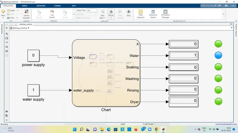
WASHING MACHINE MODEL:
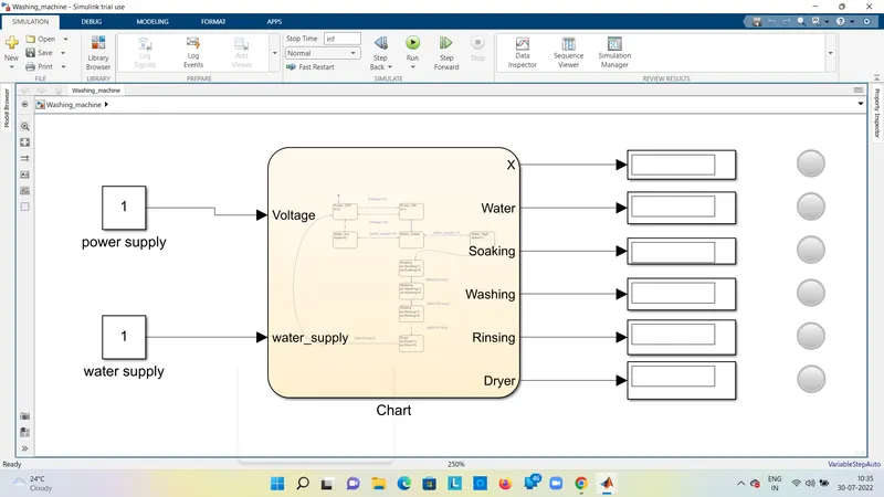
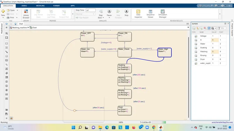
CHART MODEL:
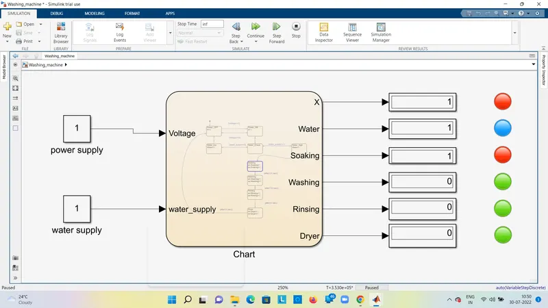
RESULTS:
1.Power and Water supply is supplying to machine , conditions are voltage==1, ws==1 is true,
further operations takes place, lamps is shows power supply pass is red,water supply is pass
blue, and further operations done is shows red.
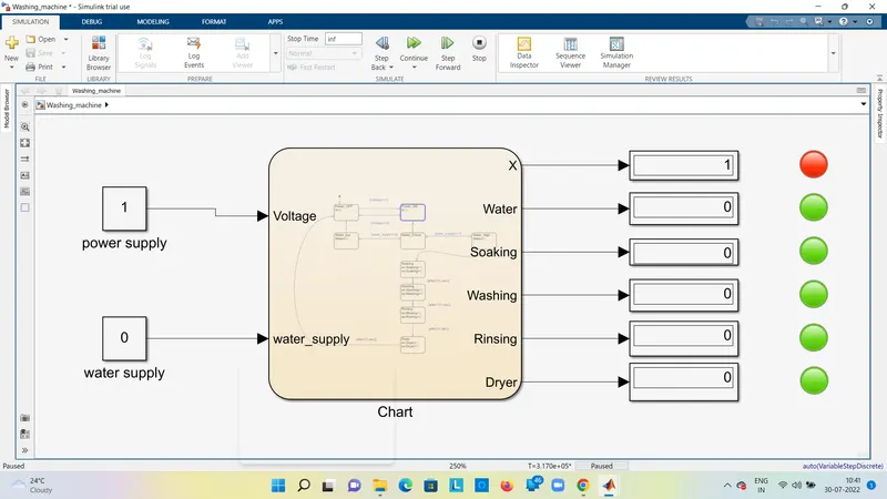
2.Power supply is pass condition voltage==1, power supply is generates but water is not supply
condition is ws==0,further operations not done, Lamp is red glows only.other lamps is green
glows no operations done.
3. Water supply s pass condition is ws==1, but further operations not done ,because of power supply
is not to pass ,Lamp is shows blue water is pass,other lamps are green ,power supply is not pass.
THEORY: Washing machine proceses:
Washing Machine is a Automatic device which perform actions on sequence of
operations actions takes, It is very usefull to the reduce time and work to us.
POWER SUPPLY: Power supply to take actions perfom operations,If no power
supply operations will not happens, Lamp will glow red colour
power will generates, Lamp will glow green no power generates.
WATER SUPPLY: If water will supply further operations will process,otherwise water
wouldn't supply ,other operation are not proceed but power supply
generates, Lamp will glow water is available to supply is BLUE COLOUR.
NO water supply Lamp wil not glow.
STATE FLOW : CHART : Washing Machine further operations.
We create a Simulink model in State flow , we proced to follow the Chart required operations
perform on them ,Machine consisting of states ,Transitions, and data, It reacts simulink external
internal signals ,events, and time-based conditons.
POWER ON /OFF: If power checks ,voltage==1 power is on, voltage==0 power is off to
check on given conditions. to generates the machine.
WATER CHECK LOW /HIGH: If checks the water level low or high, If low condition is
ws==0 further will not continue , Lamp not glow, If water is high
condion is ws==1 further operations will continue as per procedure.
SOAKING : If saok will be performed on the given time 200s , If the lamp will glow red
actions takes place, lamp is green no action.
WASHING: If washing will be performed on the given time 100s , If the lamp will glow red
actions takes place, lamp is green no action.
RINSING: If rinsing will be performed on the given time 20s , If the lamp will glow red
actions takes place, lamp is green no action.
DRYING: If drying will be performed on the given time 50s , If the lamp will glow red
actions takes place, lamp is green no action.
If the all operations are done given sequence the lamp will be glow .
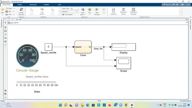
GEAR SHIFT MODEL:
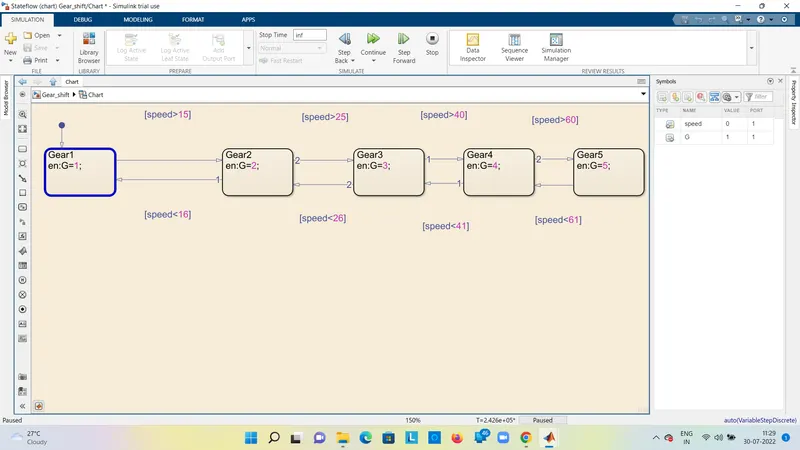
STATE FLOW CHART:
RRESULTS :
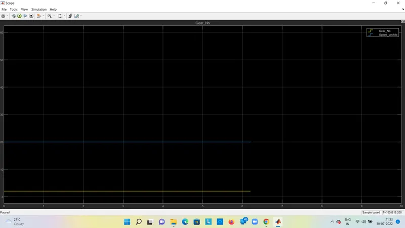
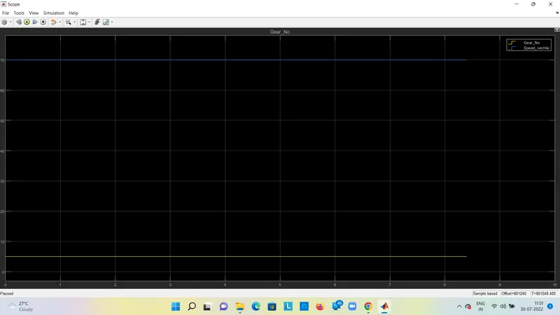
1.Simulation is running along with input speed is given slider, which input speed displays on speedometer
and speed vechile block, gear number is displays on block ,given speed is 15 to 25 btw , its shows gear 2
and scope is shows both speed and gear number.
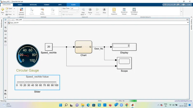
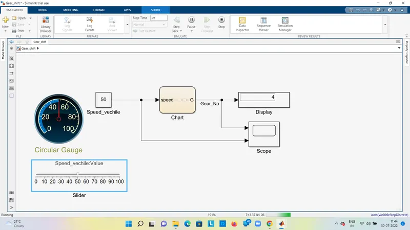
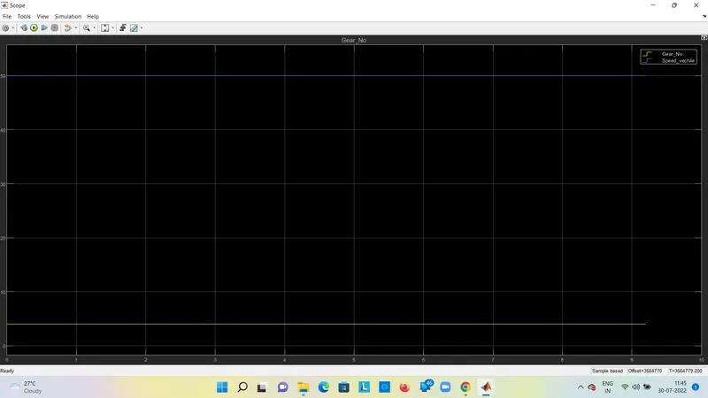
2.Simulation is running along with input speed is given slider, which input speed displays on speedometer
and speed vechile block, gear number is displays on block ,given speed is 40 to 60 btw , its shows gear 4
and scope is shows both speed and gear number.
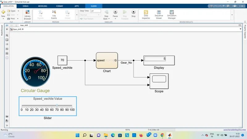
3.Simulation is running along with input speed is given slider, which input speed displays on speedometer
and speed vechile block, gear number is displays on block ,given speed is above , its shows gear 5
and scope is shows both speed and gear number.
THEORY : GEAR SHIFT :
INPUT SPEED BLOCK: If the input speed to given to change the gear required speed based on condition.
SLIDER : To give input speed along with simulation as we required speed changes.
SPEEDOMETER : The input giving speed will be display on the meter , its seems effectively understand
input speed measures and display.
STATE FLOW : CHART
We create a Simulink model in State flow , we proced to follow the Chart required operations
perform on them ,Machine consisting of states ,Transitions, and data, It reacts simulink external
internal signals ,events, and time-based conditons.
GEAR SHIFTING ALONG WITH SPEED :
1. If the input speed is less than 15 vechile moment motion is gear number 1, will be display on block.
2. If the input speed is less than 25vechile moment motion is gear number 2, will be display on block.
3. If the input speed is less than 40 vechile moment motion is gear number 3, will be display on block.
4. If the input speed is less than 60 vechile moment motion is gear number 4, will be display on block.
5. If the input speed is above 60 vechile moment motion is gear number 5, will be display on block.
All the gears are shift with given conditions.
DISPLAY : Display block is shows the output of gear number ,Which input speed is given to based on
conditions to show Gear No.
SCOPE: If scope is represents graphical both speed along with gear number, better to understand
gear shifting.