Week -2
AIM : Make a simulink block of a model Door Bell using Solenoid as given details.
Use a Thermistor to sense the Temperature of a heater & turn off fan as per the given condition.
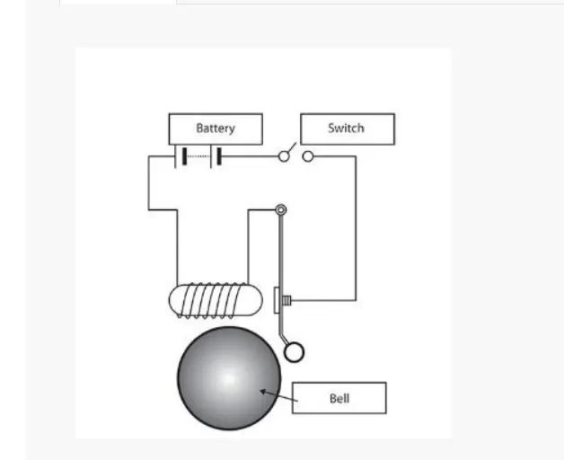
Given Door Bell Information Fig :
If the pulse generator is input ,the electromagntic solenoid is generates a sound a bell, with the battery is
current pass through solenoid,plunger is to gives sound , scope is shows graphical representation.
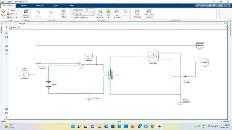
Simulink Block Model of Door Bell :
List of the blocks usess in model :
1. Pulse generator.
2.Switch.
3.Battery.
4.Solver Configuration.
5.Solenoid.
6.Scope s
7. PS simulink converter and simulink PS converter.
8.Mechanical and Electrical referenses.
PULSE GENERATOR :
The pulse generator is generates square of wave pulses of regular intervals ,parameters are
Amplitude,pulse delay,pulse width,period,phase of the pulse generator.
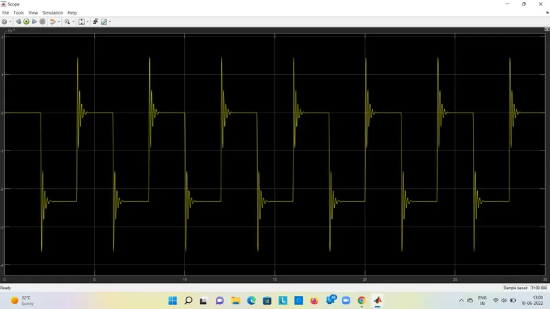
The below figure shows the graphical represents :
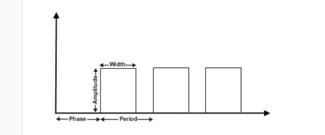
The above shows the given time to stop, the pulse generates a certain time.
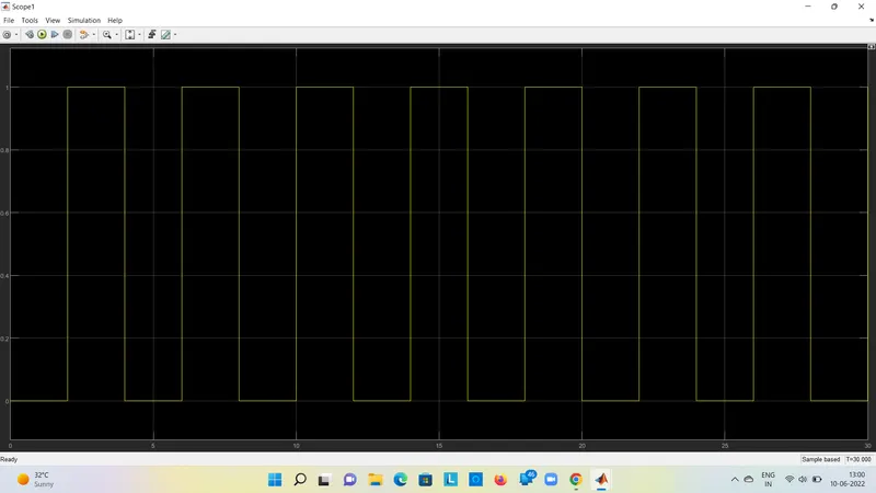
Results :
CONCLUSION ON THE RESULT DOOR BELL BLOCK MODEL :
The input is given to pulse generator with 2 secs, the stop time is given 30 secs , Door bell is sound
by these 2 secs , the spikes shown in above fig are be total is 15 means bell sounds 15 times, The
Switch is open and close ,if switch is close battery is produce a current , pass through a solenoid there
will be ideal translation sentors is from p is plungers through a sounds bell given time,the output is shows
simulink physical converters,shown in scope bell sounds, if the spring wire is constant reducing, value of damping
is vibrations reduced.
What is Thermistor :
Thermistor is a device which measures a temperature ,it works on relationship between resistance and temperature.
Here in simulink thermistor block is positive temperature co-efficient thermistor.Resistance is increases or decreases
with respect to temperature.The output is voltage or current .The increases is voltage/current indicates increase in
temperature.
CONTROLLED TEMPERATURE SOURCE :
This block is ideal source of thermal energy that is powerful enough to maitain a specified temperature differencess
from heat flow.
The ports A and B are the thermal input and output respectively, Port S is the physical controlled signals .
RESISTOR:
This linear resistor ,from below equation
V=I.R
where ,V =Voltage
I=Current
R=Resistance
VOLTAGE SENSOR:
This device converts the voltage measured between electric circuits into physical signals to voltage.
ELECTRICAL REFERENCE:
Its represents an electrical ground . Electrical conserving ports of all blocks are conected atleast one of the
electrical references.
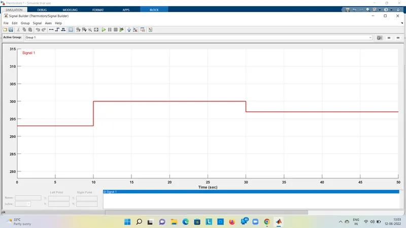
The above model is signal block is used to give temperature ,to given in challenge , temperature signal is
controlled temperature source (heater).
0-10 secs 20 degree celsius
10-30 secs 27 degree celsius
30-50 secs 23 degree celsius
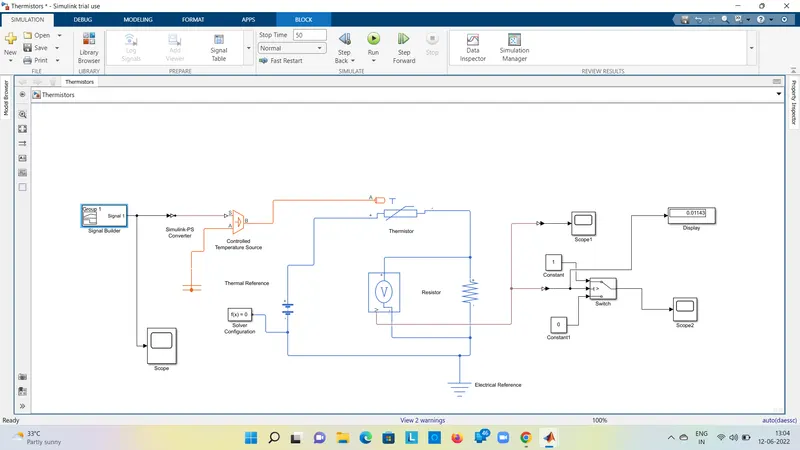
The Temperature source (heater) is sence it to thermistor .Now to run fan should be greater than 25 degree celcius.
To fullfill this objective we use a voltmeter to find voltage of the circuit at different temperatures. found voltage at
25 degree celcius is approximately 0.01143V , Which is gives switch to threeshold value , switch is configured that value ,
If switch is open on lessthan threeshold value ,other switch is close greaterthan threeshold value. The Threeshold value
is set 0.01143.
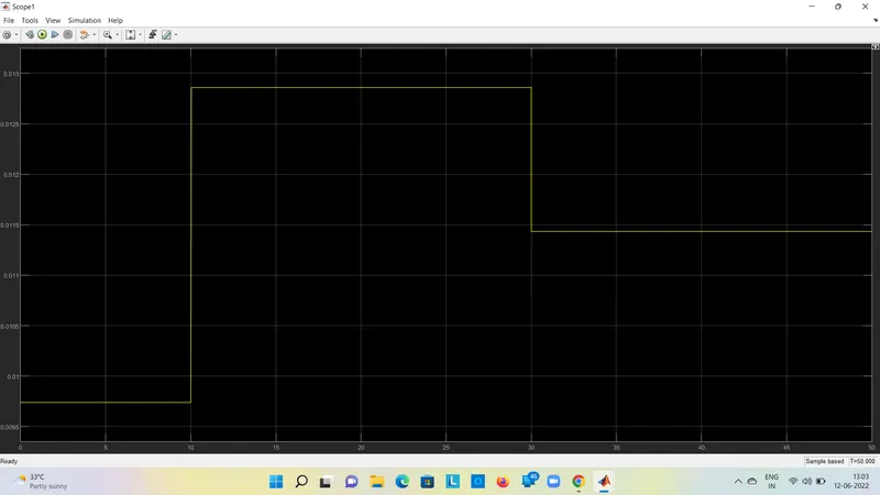
From the Switch output we can see that,only output is between is 10-30 seconds as the temperature is greater
than the 25 degree celsius. So, this output is turn on the fan for the simulation