Week - 4
Part 1
Control Logic Using Stateflow for Washing Machine
---
Aim
To model a control logic for a washing machine in Simulink and Statflow.
Objective
Implement control logic of a “washing machine” using Stateflow as per given sequence:
- If the power supply is available, the system gets activated
- If the Water supply is not available, stop the process & indicate through LED
- Soaking time should be 200s followed by Washing time of 100s.
- Then rinsing happens for next 20s & dryer runs for 50s
After all the processes have completed turn on the finished LED
Solution
Stateflow is a control logic tool used to model reactive systems via state machines and flow charts within a Simulink model.
Simulink Model
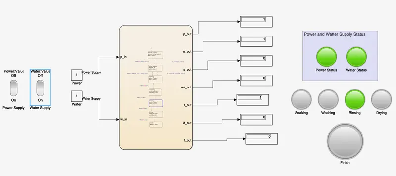
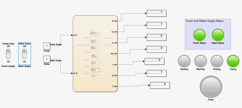
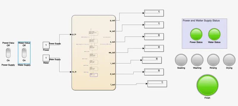
Following is the stateflow model of the washing machine:
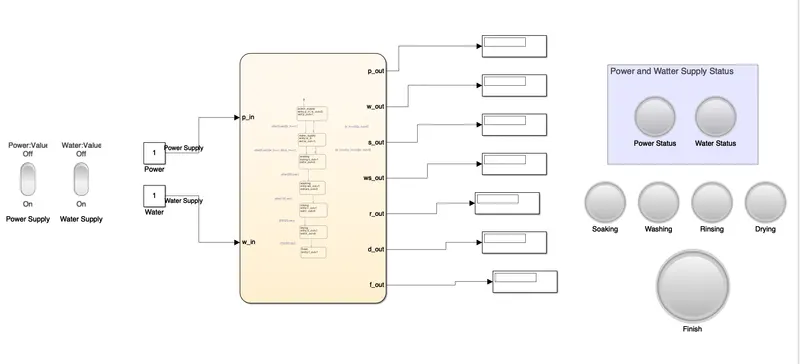
Blocks Used are:
- Simulink Switch
- Constant
- Display
- Lamp
- Stateflow Chart
Explanation
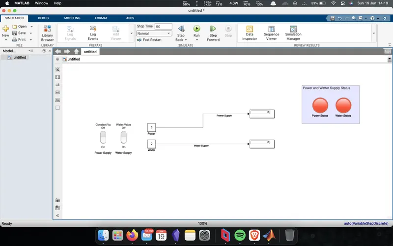
To start with, initially the control logic for the water supply and power supply was modelled using switch block and constant block, with input to constant block is connected to the switch to dynamically update the state during simulation, similarly the output serves as the input to the lamp to indicate the status respectively, as shown below.
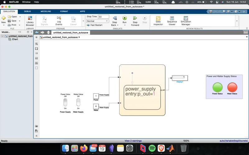
Further to implement the control logic for each state of a washing machine such as soaking, washing, rinsing and drying, a stateflow flow diagram was implemented to control each state of the machine's process and indicate the process using lights (lamp).
The input to the stateflow diagram is provided using constant block and output is indicated using display block. The lamps for the respective process is connected to the respective output display block.
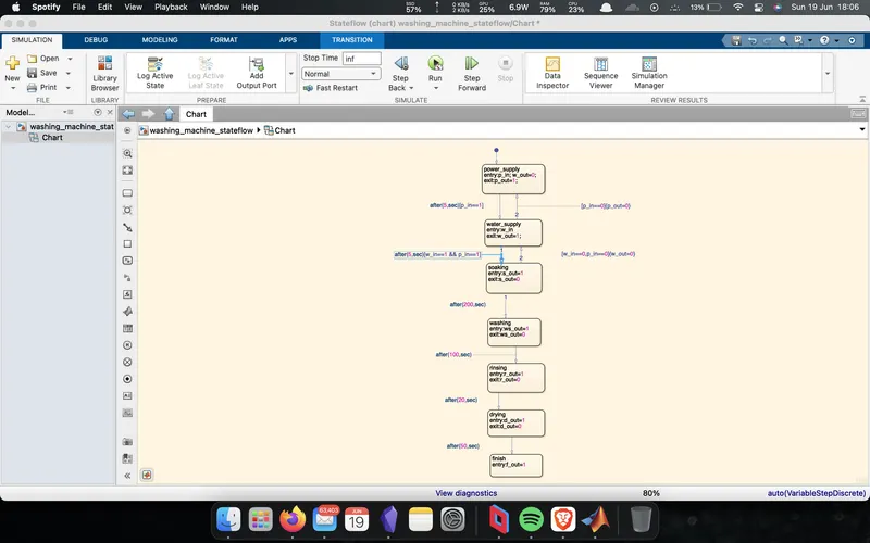
The control logic is built as explained:
- Initially the stateflow logic starts with the power supply status and checks if the power supply is on or off and accordingly indicates the lamp and enters next step.
- In this step, it checks for water supply using the on of switch and indicates using lamp.
- The next four steps are followed in sequence with some delay provided between each step to simulate the soaking, washing, rinsing and drying stages of the machine.
- Finally after all the stages, the finish status is indicated using a lamp.
Result
Step 1 (Turning ON Power Supply)

Step 2 (Turning ON Water Supply Supply)
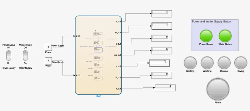
Step 3 (Soaking)
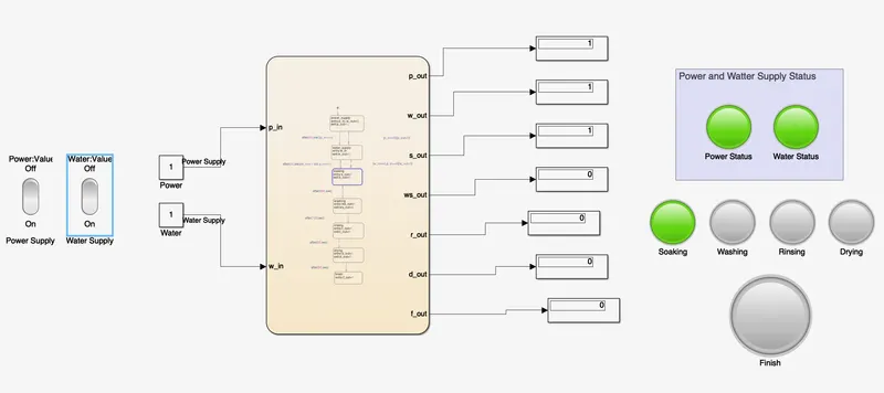
Step 4 (Washing)
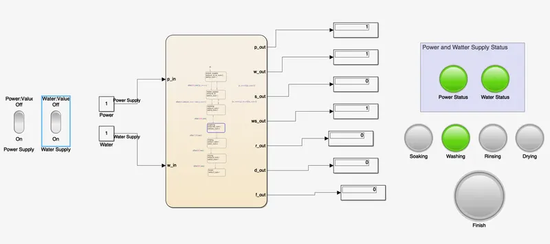
Step 5 (Rinsing)
Step 6 (Drying)
Step 7 (Cycle Finish)
Part 2
Control Logic Using Stateflow for Gear Shift
---
Aim
To model a control logic for gear shifting mechanism in Simulink and Statflow.
Objective
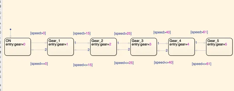
Make a Simulink chart for the “Gear shift” logic as per below conditions:
Speed Range(kmph) Gear
0 to 15 1
16 to 25 2
26 to 40 3
41 to 60 4
Above 61 5
Give speed input while the simulation is running & display the gear number.
Solution
Stateflow is a control logic tool used to model reactive systems via state machines and flow charts within a Simulink model.
Simulink Model
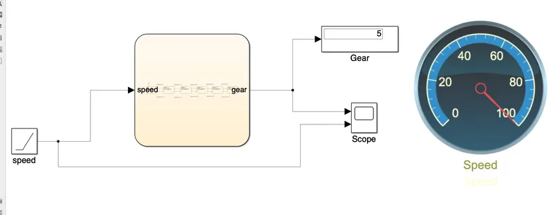
Blocks Used are:
- Ramp Block
- Display
- Scope
- Gauge
- Stateflow Chart
Explanation
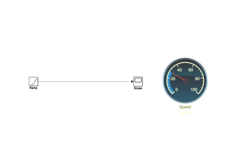
Initially the basic requirement for the model to function correctly is modelled using simple simulink blocks such as ramp block to simulate the acceleration from 0 to 100 kmph and to visualise the speed in realtime during simulation a gauge is used to display speed output as shown below.
The gear shift logic is modelled in the stateflow chart as per the given conditions as shown below.
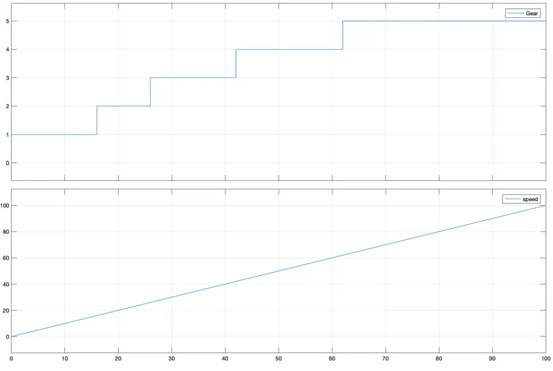
Output of the current logic is plotted using a scope block to generate graphs.
Result
Following is the simulation result: