Week - 4
Q1) Implement control logic of a “washing machine” using State flow as per given sequence:
a) If the power supply is available, the system gets activated
b) If the Water supply is not available, stop the process & indicate through LED
c) Soaking time should be 200s followed by Washing time of 100s.
d) Then rinsing happens for next 20s & dryer runs for 50s
Simulink Model Development
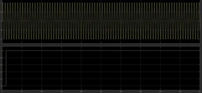
1) Input condition for Power supply is considered as sine wave
Reason: since power supply for washing machine is AC in practical
2) Input condition for water supply is considered as step function i.e., 0 for first 10 sec and 1 for remaining time.
Reason: To display water supply off condition using Led lamp, 0 value for first 10 sec is considered.
3) State flow chart development for washing machine control logic
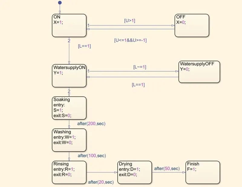
(i) Let U be the input power that flows through state ‘ON’ with a condition that U<=1&&U>=-1 and flows through state ‘OFF’ with a condition that U>1. (State transition takes place only if the condition is true).
state action or output: for ON is X=1 and for OFF is X=0
(ii) Let L be the input water supply that flows to state ‘watersupplyON’ with a condition that L==1 and flows through state ‘watersupplyOFF’ with a condition that L~=1. (State transition takes place only if the condition is true)
state action or output: for ON is Y=1 and for OFF is Y=0
(iii) From the ‘watersupplyON’ state, process starts for soaking, washing, rinsing and drying with specified time delays 200s,100s,20s and 50s respectively. (State transition takes only after th4 specified time delay)
state action or output: soaking: S=1 to S=0 during soaking time
washing: W=1 to W=0 during washing time
rinsing: R=1 to R=0 during rinsing time
drying: D=1 to D=0 during drying time
(iv) From the state Drying, the transition to final state Finish is considered to display the process completion through Led lamp.
state action or output: F=1 for rest of the time
4) Led lamp connections
(i) Connect state output of power supply to two led lamps one for state output X=1 and one for state output X=0
(ii) Repeat the same procedure for all states. A total of nine Led lamps are connected for nine state outputs.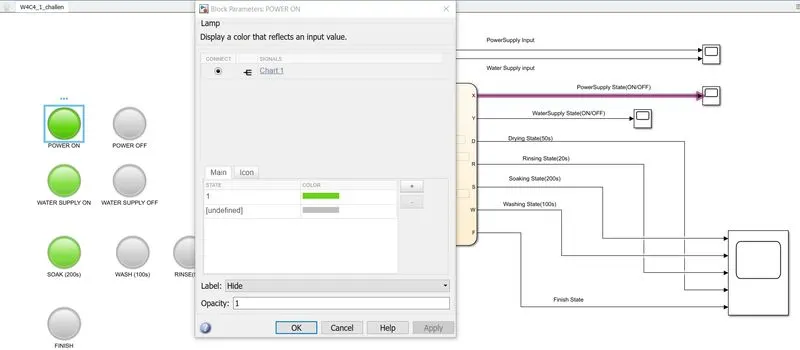
Lamp connection to output signal 'X'
Program logic or working & Results
1) Once the simulation is run, the solver checks the state flow chart for conditions to be true for state transition to take place. Here, the solver looks at the conditions of U and makes a state transition. (U<=1&&U>=-1) is true and therefore state output of ON is the output. Consequently Power supply on Lamp will glow.
2) As the solver proceeds with the time step, the second input L (watersupply) is checked for condition to be true, L~=1 is true for first 10 sec, therefore, state action of watersupplyoff is the output, the yellow LED lamp glows and no process of soaking,washing,rinsing and drying takes place.
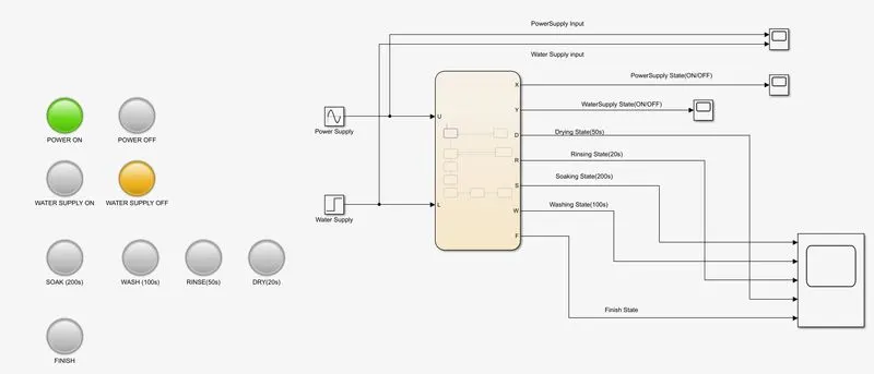
3) After 10 sec, the condition L==1 becomes true, the state transition takes from watersupplyoff to watersupplyon. The state action of watersupplyoff will be the output ans water supply led lamp glows.
4) Since process starts once the watersupply is on and therefore, state transition occurs from watersupplyon to soaking process. Soaking process Led lamp glows for 200s.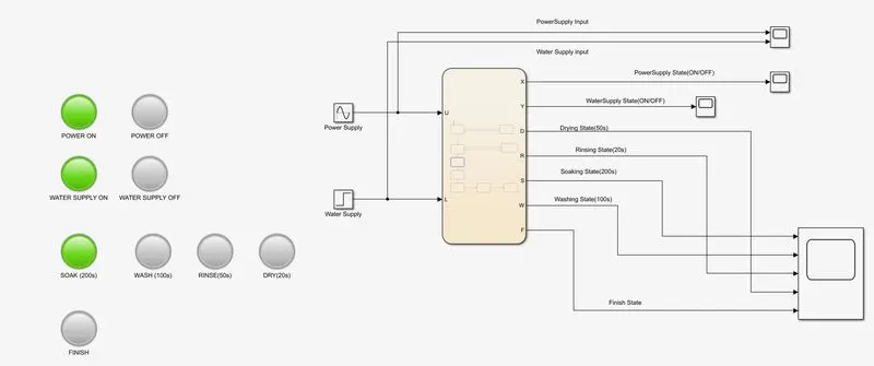
5) After 200s, state transition occurs from soaking to washing, washing Led lamp glows for 100s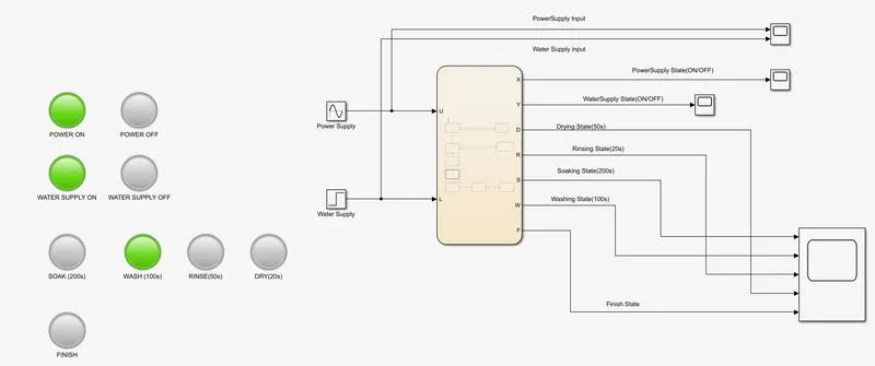
6) After 100s, state transition occurs from washing to rinsing, rinsing Led lamp glows for 20s.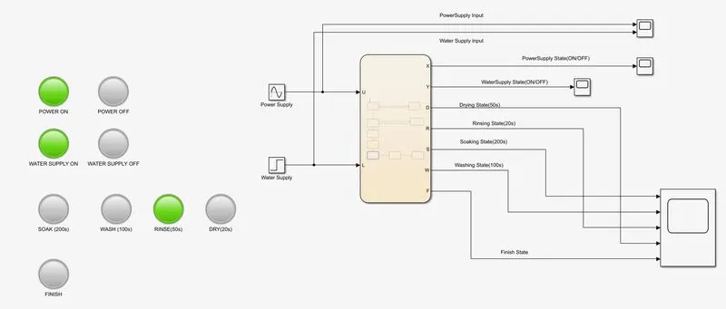
7) After 20s, state transition occurs from rinsing to drying, drying Led lamp glows for 50s.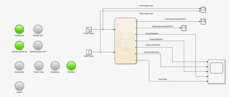
8) After 50s, the process is finished, state transition occurs from drying to finish, finish Led lamp glows for rest of the time.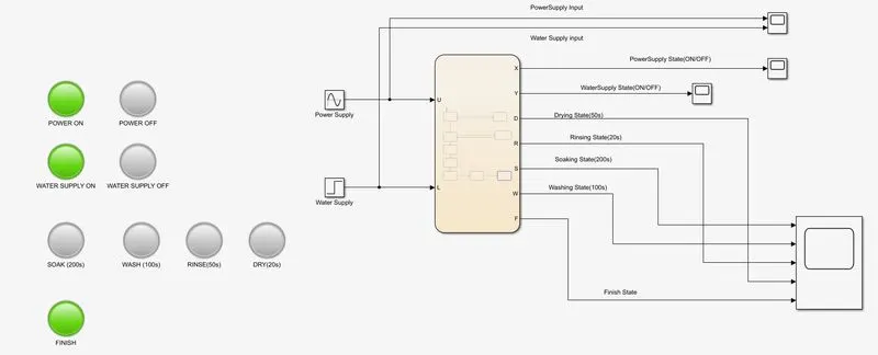
9) Process state outputs observation through scope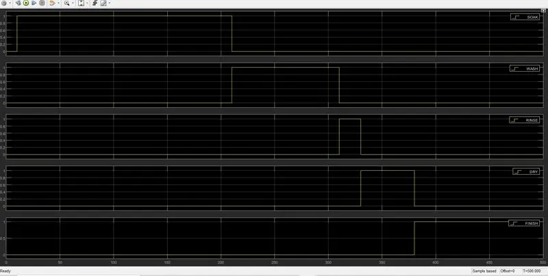
From the plot, it can be seen that the process starts after 10 sec, this is because water supply is On after 10 sec. All the processes were in condition 1 (value 1) for fixed time delays and after completion of all processes, Finish state output of 1 remains for the rest of time.
Q2 Make a Simulink chart for the “Gear shift” logic as per below conditions:
Speed Range(kmph) Gear
0 to 15 1
16 to 25 2
26 to 40 3
41 to 60 4
Above 61 5
Give speed input while the simulation is running & display the gear number.
Simulink Model Development
1) Input condition is velocity range from 0 to 100Kmph and input has to be changed while simulation is running. A constant block is taken as velocity input and a slider gain block (selected from dashboard category) it is connected to it.
Reason: As the slider pointer is moved in the range of 0 to 100kmph, the constant block parameter value is changed and therefore, the gear according the respective speed is displayed as output.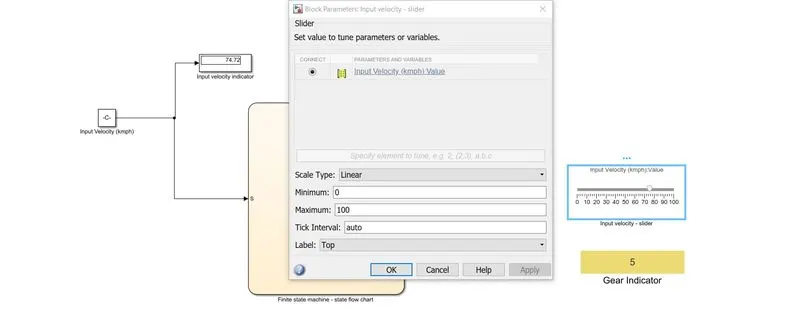
Connection of slider block to constant block
2) Stateflowchart control logic for gear indicator at respective speeds
(i) Five states are developed for five gears with an input S (constant value provided from slidergain) is as follows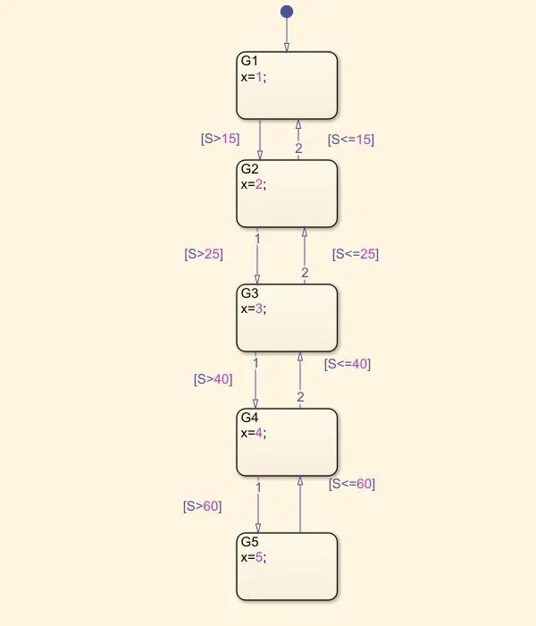
For G1 state action (0-15kmph), the condition is S<=15 and for G2 (16-25kmph), it is S<=15 and S<=25, similarly repeat the procedure for remaining states.
(ii) For gear G1 state, if the condition is true state action is x=1 and for G2,G3,G4 and G5, state actions are x=2,3,4 and 5 respectively.
(iii) To display gear number as output, the output x of state flow chart is connected to display block and the output signal is connected to display block from dashboard.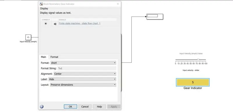
Connection of output signal 'x' to display block
Program logic or working & Results
1) Since, the input is given while simulation is running, specify the stop time as infinity.
2) As the simulation runs, move the slider in the range of 0 to 100 linearly in any direction, the input is displayed in constant block and it enters the state flow chart.
3) The solver checks the true condition of input value for the G1,G2,G3,G4 and G5 states and outputs the state actions accordingly.
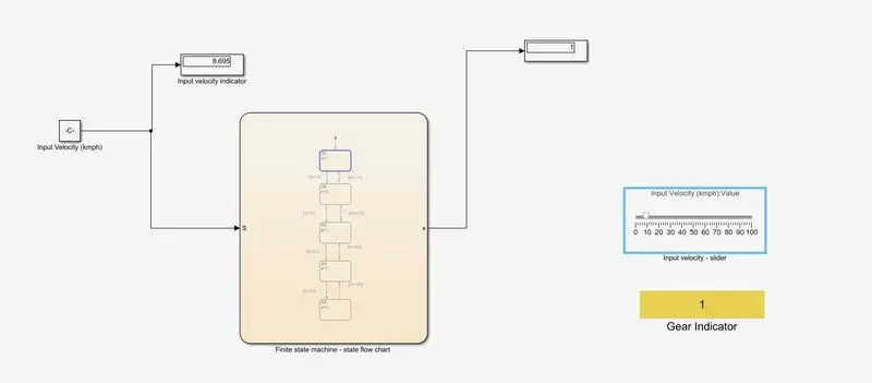
The slider is moved to velocity that is in the range of 0 to 15, the solver checks for the true condition in the state flow chart i.e., S<=15 and therefore outputs the state action of x=1. Consequently the gear indicator displays 1.
Similarly various speed inputs are given and respective gear numbers are displayed.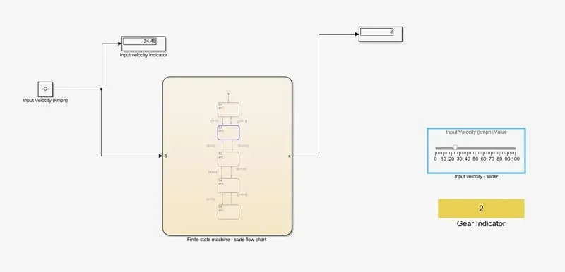
Input velocity : 24.48Kmph,defined velocity range: 15-25Kmph, state action of G2, Output = 2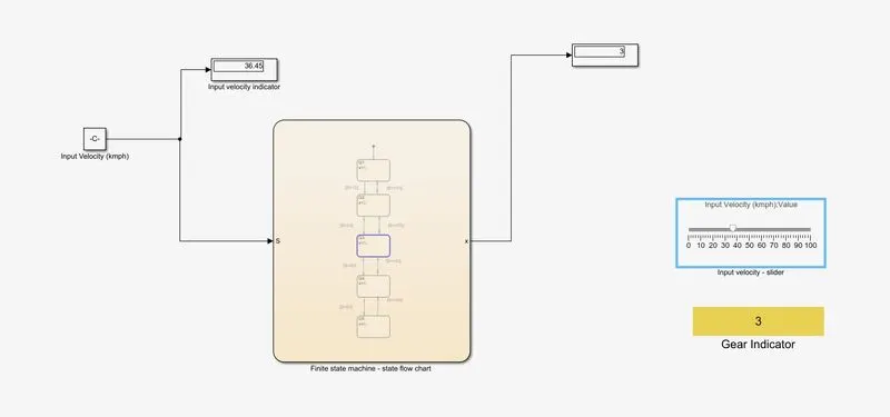
Input velocity : 36.45Kmph,defined velocity range: 25-40Kmph, state action of G3, Output = 3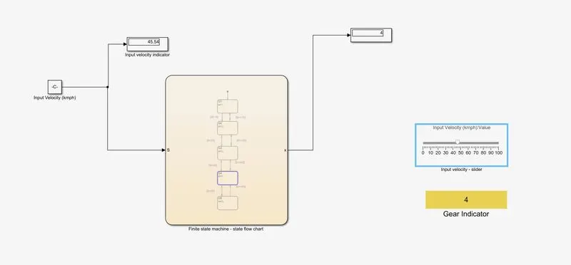
Input velocity : 45.54Kmph,defined velocity range: 41-60Kmph, state action of G4, Output = 4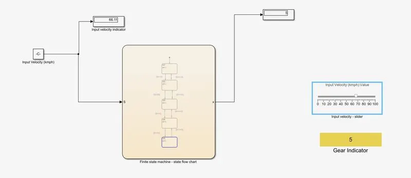
Input velocity : 66.11Kmph,defined velocity range: above 61Kmph, state action of G5, Output = 5