Week 1 Stress Concentration on a Plate with hole
- Design a plate with a hole model similar to what we worked in the class, but with increased thickness.
Determine the maximum deformation and stress developed in the model.
Objective:
- Numerical analysis of stress in a plate with holes in two given cases.
- Comparison of the results in two given cases.
- Selection of design based on analysis and manufacturing preference.
a. Numerical analysis of stress in a plate with holes in two given cases.
In solid mechanics, a stress concentration is a location in an object where the stress is significantly greater than the surrounding region. Stress concentrations occur when there are irregularities in the geometry or material of a structural component that cause an interruption to the flow of stress. A stress concentration factor (Kt) is a dimensionless factor that is used to quantify how concentrated the stress is in a mechanical part. It is defined as the ratio of the highest stress in the part compared to a reference stress.
Numerical analysis of any structural component consists of following 5 steps:
Geometry creation, Material Assignment, Meshing, Boundary condition assignment and finally solution and post-processing.
The analysis of the two cases in the present model will be explained simulataeneosuly along these lines.
Structural analysis:
1. Geometry creation
| Case-1 | Case-2 | |
| Length | 300 mm | 300 mm |
| Breadth/ Height | 120 mm | 120 mm |
| Thickness | 30 mm | 30 mm |
| Addl. Features | Circular Hole at the center: Diameter = 60mm |
Circular Hole at the center: Diameter=60mm |
| - | Smaller holes 90mm away from the center: Diameter = 30mm |
Once in Workebmch window, right click on geometry option and open spacwe claim. Create the following 2D model with above dimensions.
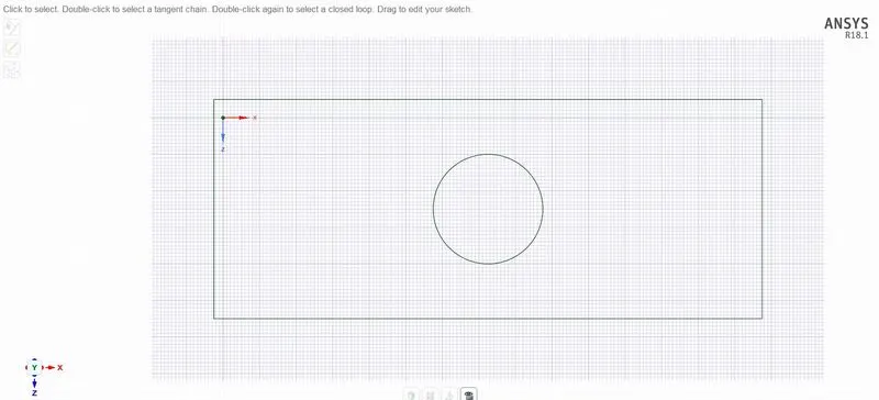
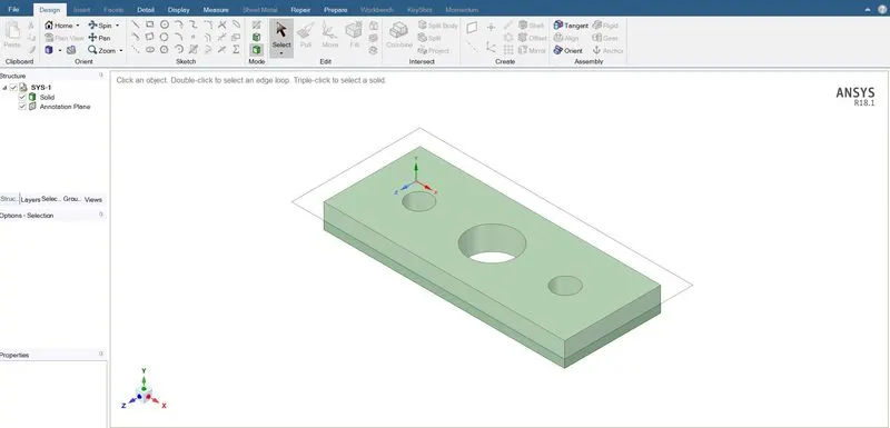
Include 2 additional circles of dia. 30 mm at a a distance of 90 mm from the centre of centre circle for case 2.
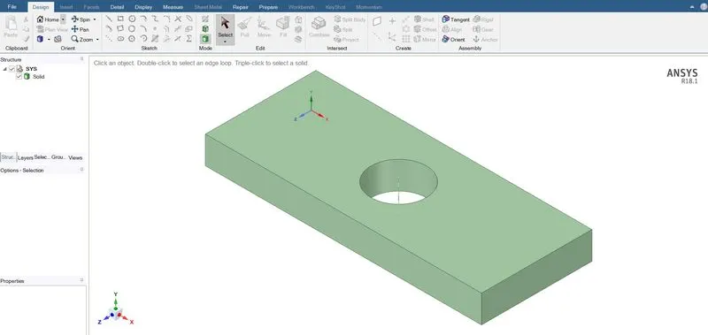
After creation of sketch, use the "pull" option to extrude the model with given thickness (i.e. 30 mm).
2. Material Selection
Material selection in Ansys workbench can be done in 2 ways.
a. Assign material in 'engineering data' in workbench window.
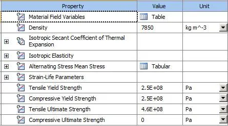
b. Update assigned material before meshing under geometry tab.

3. Meshing
Upon updating the "model" section in structural workbench window, Ansys meshes the model with a standard. However, the size of the mesh is relatively large and hence the mesh is coarse.
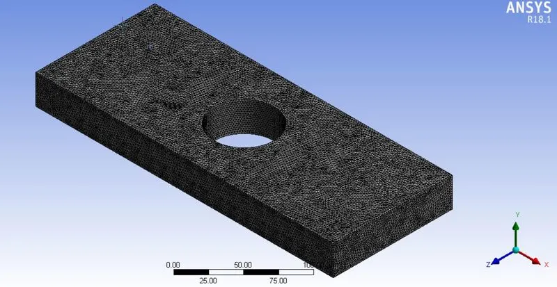
However, this problem requires a 3D mesh as the model is 3D and the stresses inside the thickness of the material needs to be studied. The mesh is updated to 3D by chosing the tetrahedral option of meshing using the "insert" option. The size is kept to 2 mm as instructed in the class.
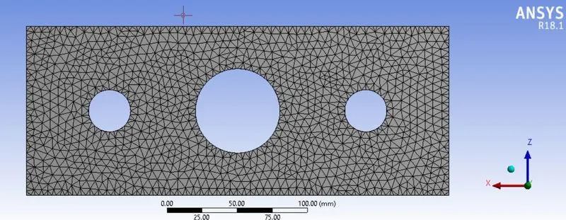
The element size for case-2 was increased to 3 mm to reduce the number of elements and reduce simulation time.
Mesh properties for both cases are as follows,


4. Boundary conditions
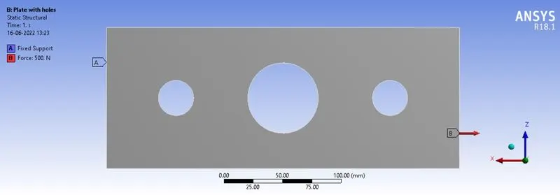
Boundary condition is the same for both cases i.e., one fixed edge and 500N force acting upon the other edge.
5. Solution and Post-processing
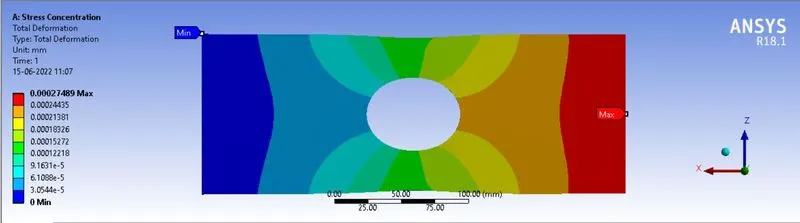
The model is solved for total deformation, Equivalent stresses and Equivalent strains.
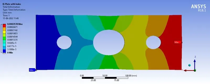
a. Total Deformation:
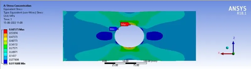
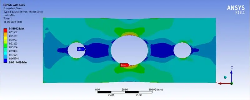
b. Equivalent stress:
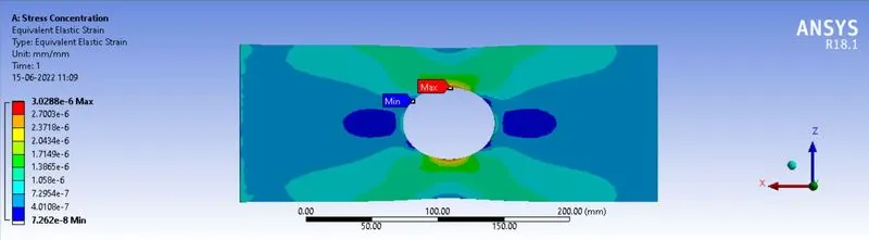
c. Equivalent Strain:
Results:
Based on the results from the report generated for the above analysis, following conclusions can be drawn
| Plate with multiple holes | Plate with a hole | |||||
| Total Deformation | Equivalent (von-Mises) Stress | Equivalent Elastic Strain | Total Deformation | Equivalent (von-Mises) Stress | Equivalent Elastic Strain | |
| Min. value | 0 mm | 0.00145 MPa | 2.23 x e^(-8) | 0 mm | 0.0167 MPa | 7.262 x e^(-8) |
| Max. Value | 0.000298 mm | 0.58 MPa | 2.9 x e^(-6) | 0.000275 mm | 0.606 MPa | 3.029 x e^(-6) |
- As per observations from Fig. 13 & 14 and the table above, it is evident that the maximum deformation occurs in plate with multiple holes.
- The elongation in plate multiple holes is 0.000298 mm whereas that in the plate with a single hole is 0.000275 mm.
- The cause for this difference lies in the lack of material in the case of plate with multiple holes. Since there is pless matter to resist the change in state of the system, the elongation is more.
- This difference is however insignificantly small i.e. 0.000023 mmand at such low loads has limited bearing on the design of the plate.
- If we focus ont the stresses generated in the two plates, the difference is more pronounced.
- The max value of von mises stresses in plate with multiple holes is 0.58 MPa whereas of that in plate with a single hole is higher at 0.606 MPa.
- The cause for this that concetration of stress at only one location i.e the cetre circle in case-1. In case-2, the stress concentration occurs at three locations and hence is less pronounced.
- The preference of either of the plates might depend on various factors including dimensional tolerence, strenght, type of application etc. From a purely analysis perspective, case-2(Plate with multiple holes) must be preferred since it exhibits a lower value of stress.
- From amanufacturing perspective, case-1 (plate with a single hole) must be preferred since it would reduce the blanking operation to just one istead of 3.