Week - 4
Assignment1
Aim: Implement the control logic of a “washing machine” using Stateflow
The sequence of operation of the washing machine:
- If the power supply is available, the system gets activated
- If the Water supply is not available, stop the process & indicate through LED
- Soaking time should be 200s followed by Washing time of 100s.
- Then rinsing happens for the next 20s & dryer runs for 50
MODEL:
Following is a pictorial representation of model
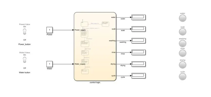
Chart diagram
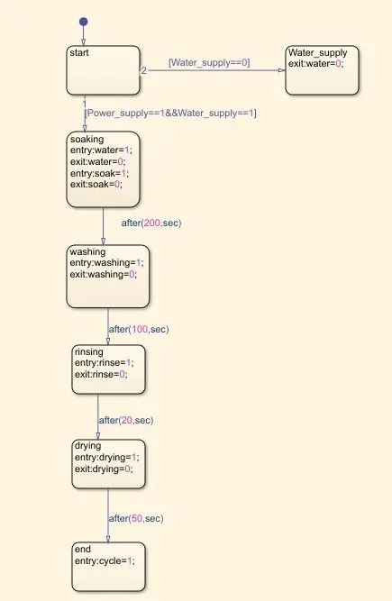
Chart explanation:
- Here we represent every sequence of actions in the washing machine by different state blocks
- here we provided power supply and water supply as two input values which are equal to 1
- at each state, we provided entry and exit output values
- also provided the delay in each state as stated in the problem
Parameters:
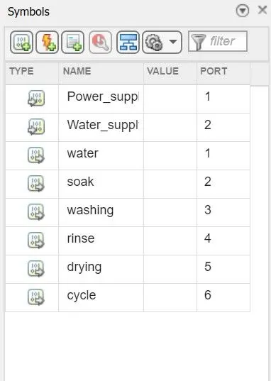
Here power supply and water supply are represented as inputs and the rest of them are outputs
CONDITION 1: When water supply is off
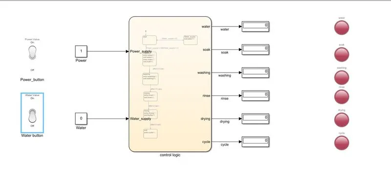
Here value 1 means there is input and value 0 means there is no input
Here we used a toggle switch to change the values of the power supply and water supply between 0 and1, as we can see that when the water supply input is '0' we get the output value of water is '0' so the process gets terminated and LED indicator used to indicate the state
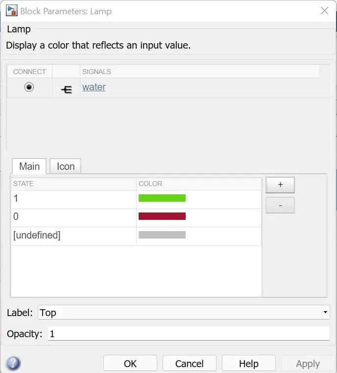
CONDITION2: When water supply and power supply are on
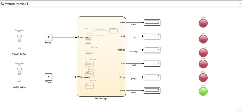
Here we can see that when power and water supply is on and feed as input value '1' every action in sequence takes place and after completion of all processes cycle lamp indicated process is finished
Assignment 2:
Objective: Make a Simulink chart for the “Gear shift” logic as per the below conditions:
Speed Range(kmph) Gear
0 to 15 1
16 to 25 2
26 to 40 3
41 to 60 4
Above 61 5
Model:
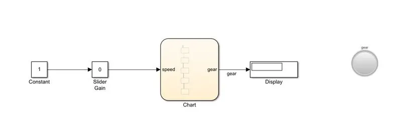
Chart diagram:
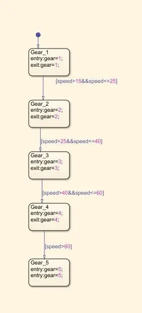
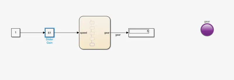
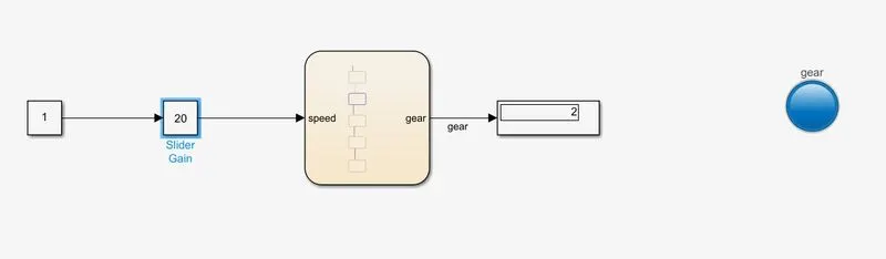
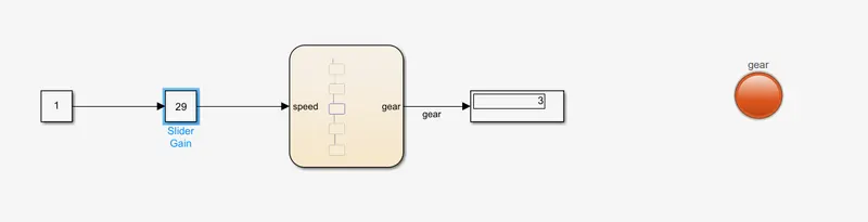
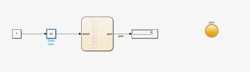
- Here is a chart for each state, we take the output value like 1, 2, 3,...5 and added the speed limit as a condition(as per question) between each state block
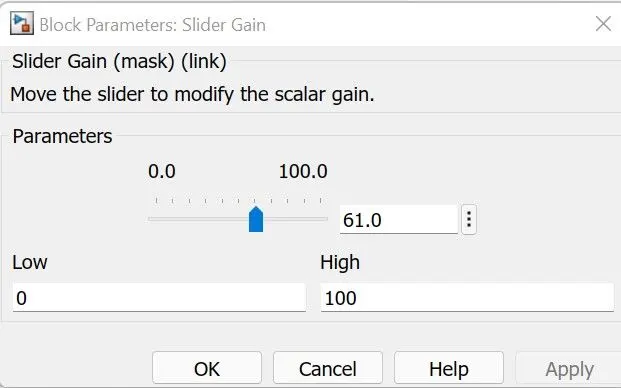
- simulation stop time is set to infinity and here we use slider gain to change the input values during the simulation and check how the output value for each speed condition changes
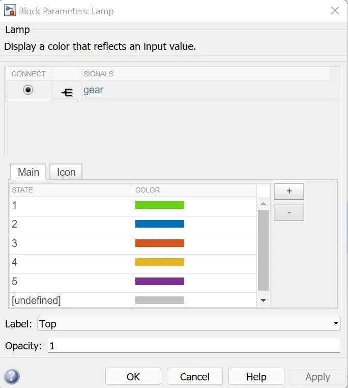
- Also, the lamp is connected to output values of gear and each output is assigned to different color
Gear 1:
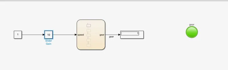
As we can see slider gain is kept between 0 to 15 so in the display we can see the output value as '1' and accordingly lamp changes to the color assigned for that value
Gear 2:
Gear 3:
Gear 4:
Gear 5: