Week -2
TASK 1: Make a Simulink model of a Doorbell using a solenoid block
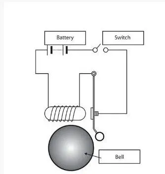
In the above arrangement, when the switch is closed the electromagnet receives electrical power from the battery and pulls the metal arm to hit the bell producing sound.
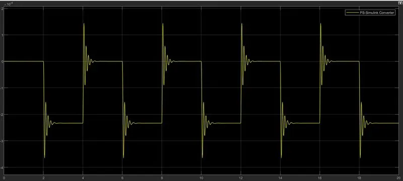
Create a situation where the switch is closed for 2 seconds and then released. Observe the physical movement of the plunger
Simulink model:
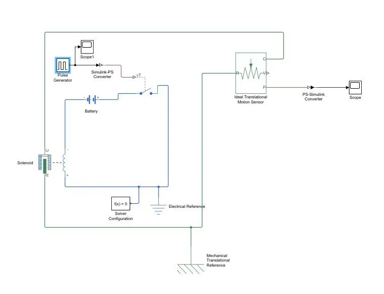
Working of the model:
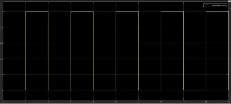
- Pulse generator creates input signal pulse 1 unit amplitude for 4 sec period having 50% pulse width with 2-sec delay for the model
- Then we attach a scope to compare the plot the with outputs
- then it converts into the physical signal by Simulink to ps converter and feeding it to SPST switch
- SPST switch compares the input signal to its threshold voltage and if it is greater than it closes the circuit or else kept it open
- solenoid gets charged by battery and it pulls R towards C (same as metal arm gets pulled to hit the bell and produce the sound)
- An ideal translation motion sensor block is connected to solenoid part R which reads its position and velocity
- To plot its positions it is connected to scope through ps to Simulink convertor
The plot of the input pulse generator
The plot of plunger motion
TASK 2: Use a thermistor to sense the temperature of a heater & turn on or turn off the fan as per the given conditions.
Condition: Temperature source: 20 °C from 0 to 10 seconds, 27 °C from 10 to 30 seconds, 23 °C from 30 to 50 seconds
Fan conditions: ON if the temperature is above 25 °C, OFF otherwise
Thermistor: A thermistor is a type of resistor whose resistance is strongly dependent on temperature, more so than in standard resistors. The word thermistor is a portmanteau of thermal and resistor.
Thermistors are divided based on their conduction model. Negative Temperature Coefficient (NTC) thermistors have less resistance at higher temperatures, while Positive Temperature Coefficient (PTC) thermistors have more resistance at higher temperatures. Hence, a PTC thermistor's resistance is directly proportional to temperature.
Simulink Model:
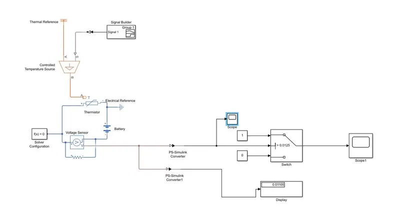
Explanation of model:
- In the above model, the thermistor is used to sense the temperature and vary the voltage and switch is used to start or stop the fan
- here we add the NTC thermistor block and its T port is connected to the ideal temperature source
- S port of temperature source is connected to signal builder block through Simulink to ps converter
- In signal builder block is set according to input given
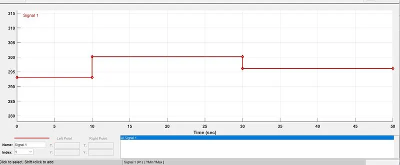
- battery and voltage sensor is connected in series and resistance in parallel and electric reference is used as a ground to system
- The voltage sensor is connected to a switch to control the fan we put a scope also to read the threshold value of voltage and set the switch with a same threshold value
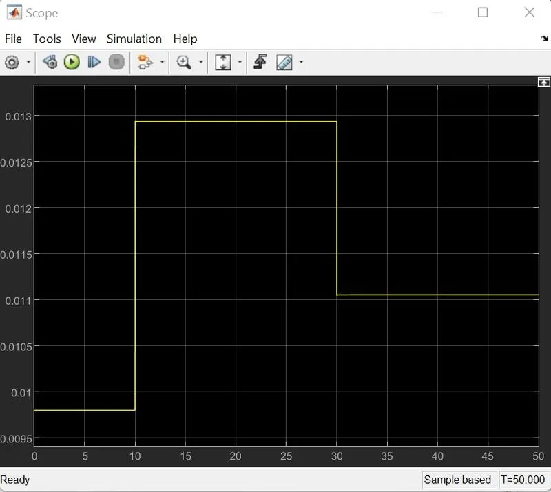
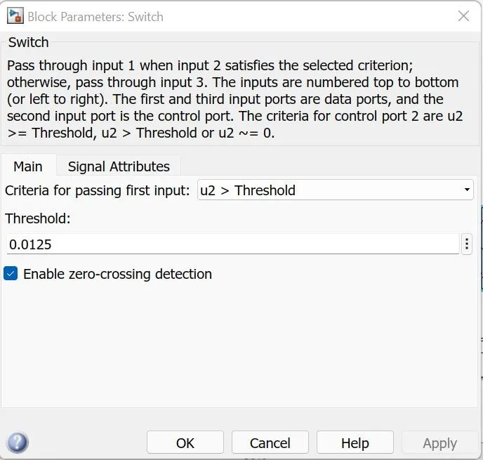
- here the switch value crosses the threshold limit it switches to '1' as output which means the fan Switch on or else the fan is Switch off
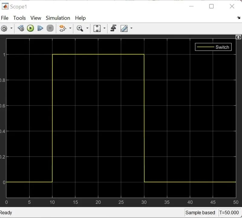
As we can see in the above plot between 10 to 30 sec fan turn on as it crosses the threshold limit
Link for Simulink models:
https://drive.google.com/drive/folders/16VAluLg2nEIcz0tbIe3xzwTcCfW_krwN?usp=sharing