Week - 4
Ans_1)
The input to the chart is the power & the water supply.
Power can be 0 or 1, constant block is used with the switch to turn power ON(=1) & OFF (=0)
Water supply can be 0 & 1, constant block is used with the switch to tune the water supply ON(=1) & OFF (=0).
The RED lamp will glow if water supply is not given (=0). (refer image-1).
Constant green lamp will glow at the end of the operation implying that process is complete (refer image-2).
In the output the lamp is attached with every process.
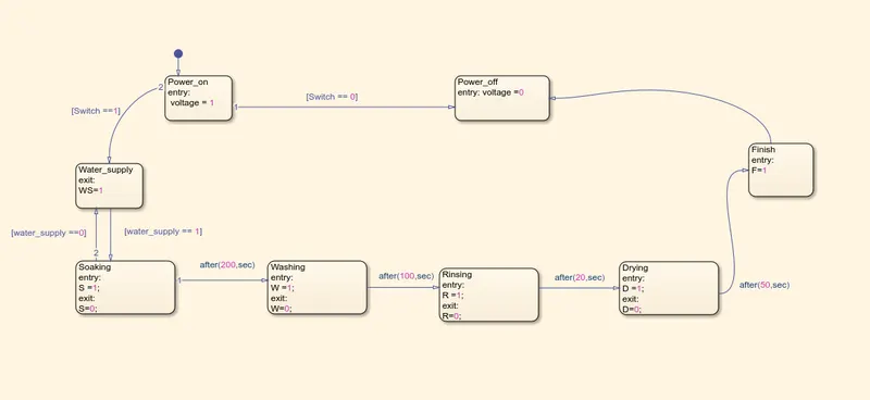
Complete logic chart is attached in the image-3.
IMAGE-1
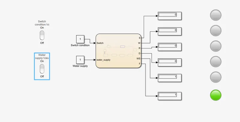
IMAGE-2
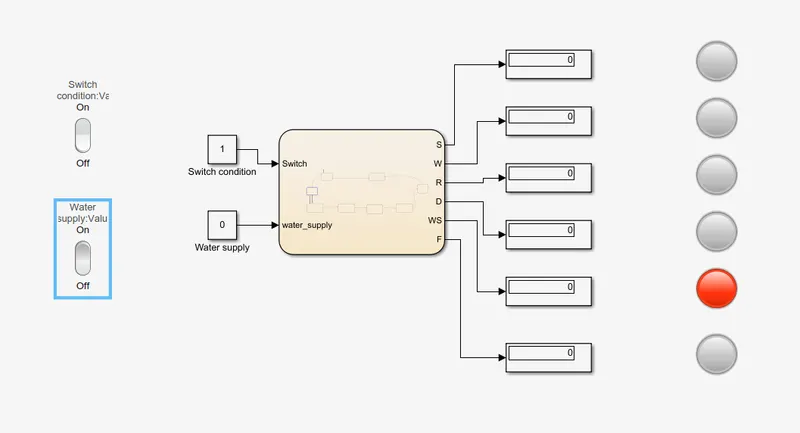
IMAGE-3
ANS-2
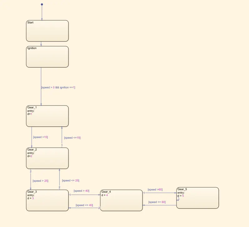
In the gear logic, downshifting & upshifting of gear is dependent on the speed condition. Refer IMAGE-5
Gear No. is displayed in the output
The speed & ignition condition is given as input. Speed is controlled by the slider(0-100). Refer IMAGE-4
IMAGE-4
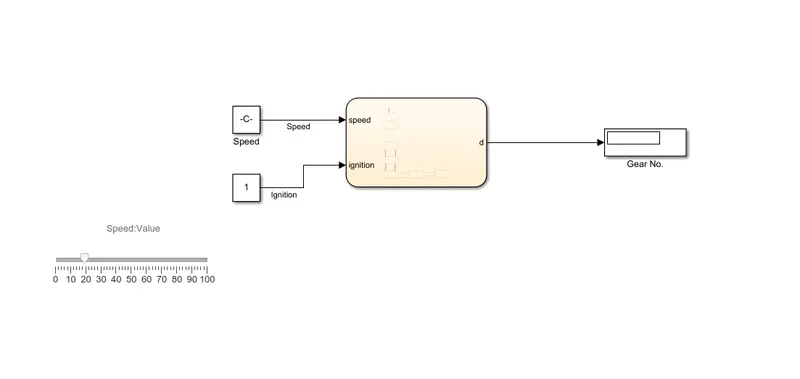
IMAGE -5