Week - 4
AIM : To make Simulink Chart of control logic of ‘washing machine’ and ‘Gear shift’ as per given conditions
Objective 1 :
To implement control logic of a “washing machine” using Stateflow as per given sequence:
- If the power supply is available, the system gets activated
- If the Water supply is not available, stop the process & indicate through LED
- Soaking time should be 200s followed by Washing time of 100s.
- Then rinsing happens for next 20s & dryer runs for 50s
Blocks Used:
- Chart
- Display
- constant
- Lamp
- Slider switch
Connection Logic:
- Switch from the dashboard library is used with a constant to connect power and water supply.
- Lamp is used to indicate the power and water status at entry of each state.
- The timing for each state is per the given inputs.
Logic Chart :
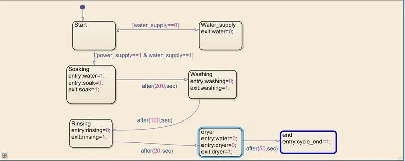
- Initially there are two conditions for the machine to activate is power supply and water supply.
- the conditions get satisfied to move moachine to further processes.
- four processes are involved in running of washing machine. i.e, Soaking, Washing, Rinsing and Dryer.
- Each process have there timing and sequence which in provided accordingly in the inputs.
- The dryer doesnt need water so, water is switched off in drying process.
- Lamp block is used as an indicator to show the finished process.
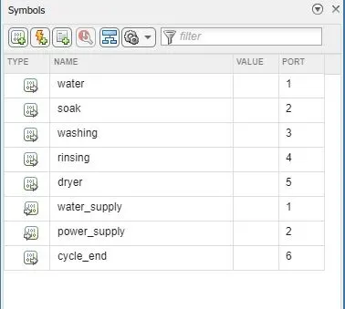
Symbols Pane:
Block Diagram:
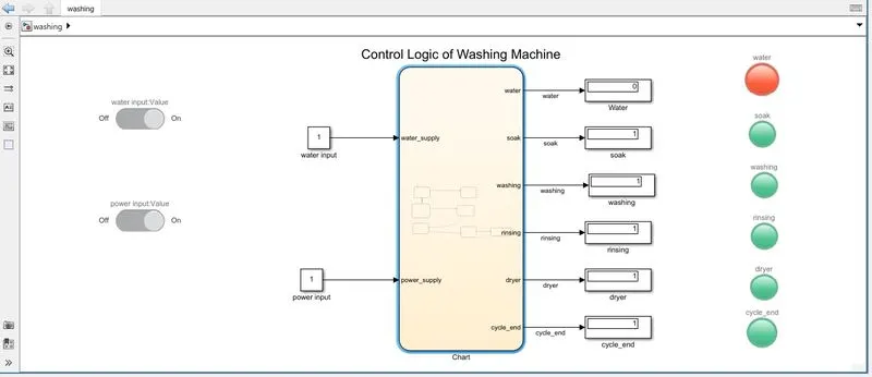
In Display 1 means data or 0 means no data, so 1 means task finished and 0 means not done or yet to be done.
green indiacator means that process is done
( water supply is red beacause washing completed so water is switched off)
Link to the model:
https://drive.google.com/file/d/1iDNcZJ64dl9qYKcvvYA6cP6JalxazDO4/view?usp=sharing
Conclusion:
Simulation of Washing machine using Stateflow is done and result is satisfactory.
Objective 2:
Make a Simulink chart for the “Gear shift” logic as per below conditions:
Speed Range(kmph) Gear
0 to 15 1
16 to 25 2
26 to 40 3
41 to 60 4
Above 61 5
Give speed input while the simulation is running & display the gear number.
Blocks Used:
- Chart
- Display
- Constant
- Lamp
- Slider Switch
- Slider
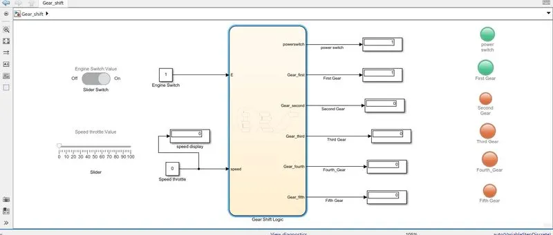
Connection Logic:
- Engine is turned on/off using the slider switch
- The speed ranges from 0 to 100 and the slider is used to send the inputs.
- The 1st gear has speed values from 0 to 15, 16 to 25 is the range of 2nd gear and similarly is upto 5th gear.
- So the entry and exit conditions of the state is given accordingly to the data provided in question.
- The display block is connected to show the data output of the of every state.
- Lamp is used as gear number indicator.
Logic Chart:
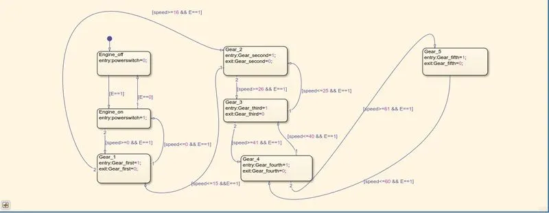
Conditions for the transtion of gear shift is input accordingly to the given data in question
As speed increases the gear also gets shifted to higher numbers Similarly shifted downwards if speed decreases.
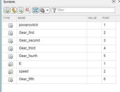
Symbol Pane:
Simulink Block Diagram at different speeds:
speed = 0
Now, running simulation for infinite seconds and block diagram at speed = 50.
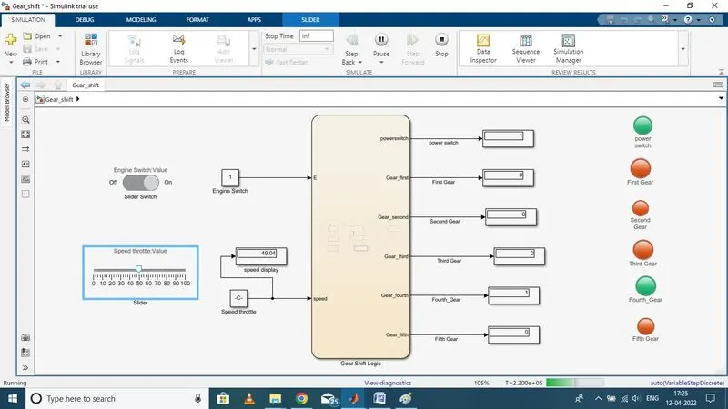
here, we can see that at speed 49 gear is fourth gear and same indicator is green.
Link to the model:
https://drive.google.com/file/d/1tSrA9aMna2tlKmclLOrc5hw_wxWlJyRB/view?usp=sharing
Conclusion:
Created stateflow for the gear shift in simulink and the results are satisfactory.