Week - 4
SIMULINK MODELLING OF WASHING MACHINE AND GEAR SHIFTING USING STATE FLOW CONTROL LOGIC
I. MODELLING OF A GEAR SHIFT MECHANISM USING STATE FLOW CONTROL LOGIC:
AIM:
To design a control logic of a washing machine using Stateflow as per the given specification.
OBJECTIVE:
- If the power supply is available, the system gets activated
- If the Water supply is not available, stop the process & indicate through LED
- Soaking time should be 200s followed by Washing time of 100s.
- Then rinsing happens for the next 20s & dryer runs for 50s
Principle:
A machine that is capable of handling various tasks like washing, rinsing, drying, and soaking within a short period, and all the task performed by the machine is based on centrifugation. It is a separation process that uses centrifugal force to promote the accelerated settling of particles in a solid-liquid mixture.
Process involved:
- SOAKING: The process in which the clothes are to be soaked at a certain time from the water supply and then washing of clothes occurs.
- WASHING: The process of cleaning the clothes in water with the use of soap or detergent.
- RINSING: The Process that makes use of fresh plain water till the residue of the soap or detergent is completely gone in the clothes
- DRYING: The drying operation performs to dry the clothes with the use of a heater.
GIVEN CONDITIONS:
- Soaking 200 secs i.e., from 0-200secs
- Washing 100 secs i.e., from 200-300sec
- Rinsing - 20 secs i.e., from 300-320secs
- Drying - 50 secs i.e., from 320-370secs
Modeling of automatic washing using state flow logic control:
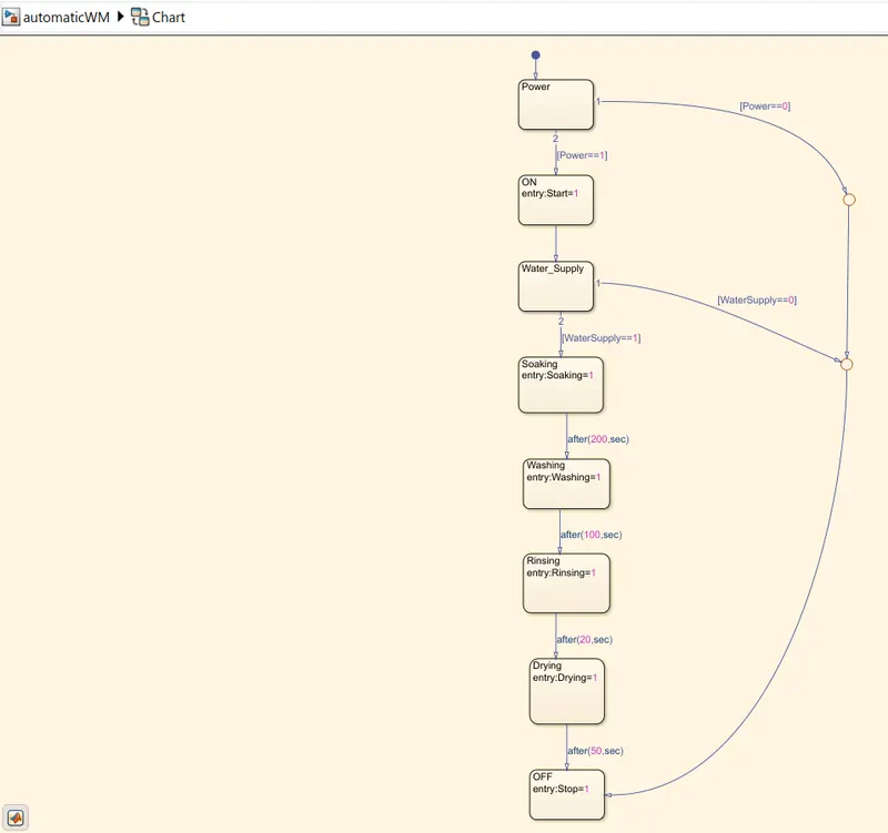
To create a state flow model, we use a Chart block in the Simulink and the logic used inside this State flow model is;
- States
- Transitions
- Junctions
- Conditions
STATE FLOW CHART:
INPUTS AND OUTPUTS PORTS:
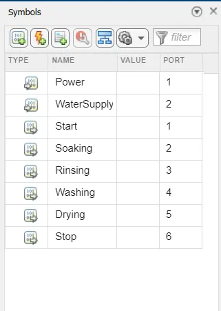
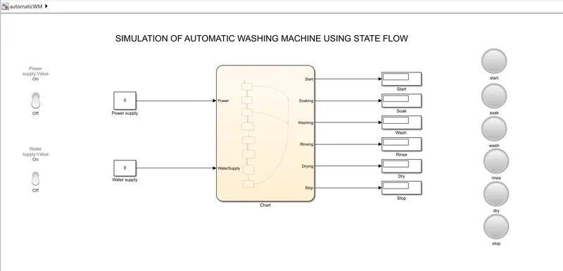
In the symbol label, We assign the input and output ports. Here the power and water supply are assigned as input ports while, Soaking, Rinsing, Washing, and Drying as assigned as output ports of the state flow blocks. which further is connected to the various Simulink blocks in the main design as shown below.
CONSTRUCTION AND WORKING:
Inside the Chart block, we have applied all the processes through various which are required in this model.
At First, we used a State block that has a Default Transition flow line. We denoted this block as a Power which consists of two initial Conditions as [Power==1 & [Power==O] to represent ON & OFF respectively.
- If the Power is ON then it will start the machine.
- Once the machine gets started it will check whether the Water Supply is available or not, based on the condition [Watersupply==0]&[Watersupply==1]. if it is available then it will turn ON the Water Supply.
- [watersupply==1] represents water supply is available whereas [Watersupply==0] represents water supply is not available.
- After supplying the water, it will begin its process by Soaking for about 200 seconds.
- Then Washing for about 100 seconds.
- Rinsing for about 20 seconds.
- Later Drying for 50 seconds.
- Once the clothes were dried properly then the machine will be made to Stop as per the logic.
- During this, we added a Junction that’s to represents any OFF conditions that will directly lead to Stopping the machine.
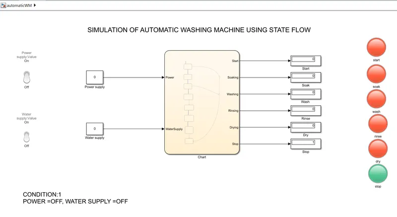
CONDITION:1
The power is OFF and the Water supply is OFF
CONDITION:2
The power is ON and the Water supply is OFF
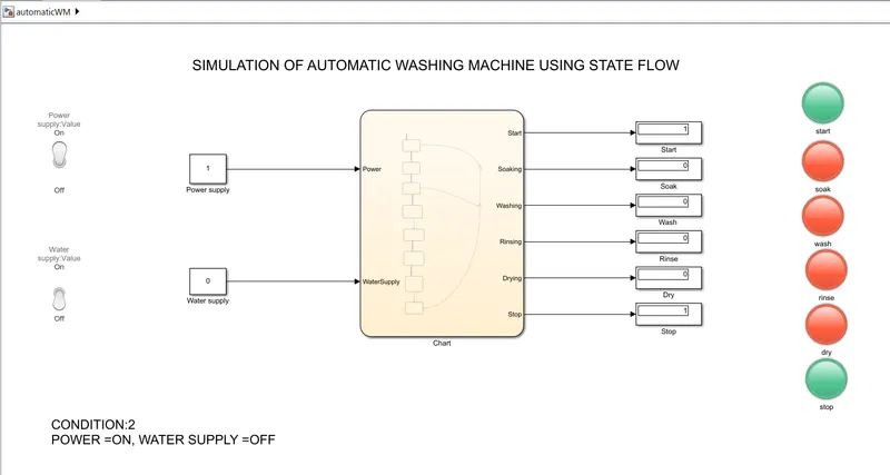
If the power is turned ON while the water supply is OFF, The indicators which display red indicate that the logic is not executed and the power turns off.
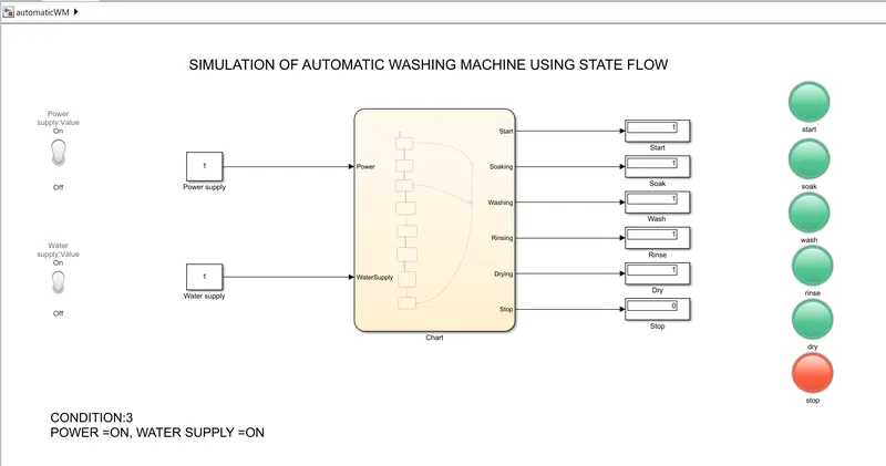
3. CONDITIOThe power
Power is ON and Water supply is ON
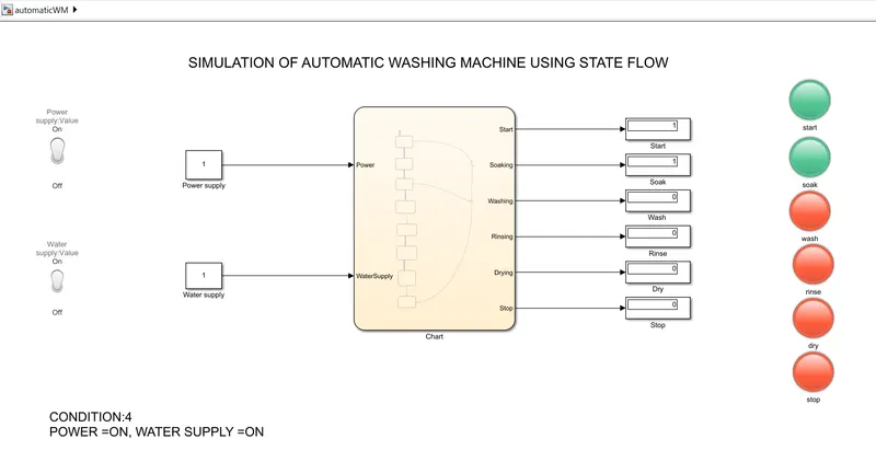
CONDITION:4
Soaking process: When the machine runs for 200 seconds, the making process is activated
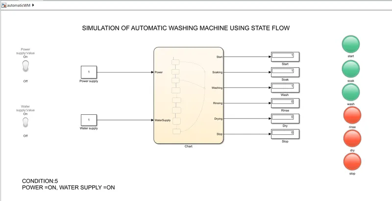
CONDITION:5
Washing process: When the machine runs for 300 secconds, the Washing process is activated.
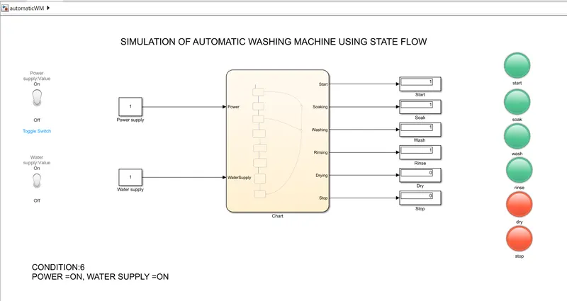
CONDITION:6
Rinsing process: When the machine runs for 320 secconds, the rinsing process is activated.
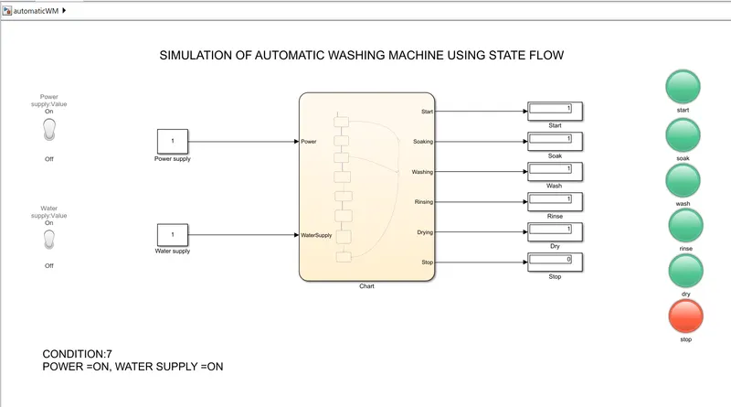
CONDITION:7
Drying process: When the machine runs for 370 seconds, the drying process is activated and then the machine stops.
II. MODELLING OF A GEAR SHIFT MECHANISM USING STATE FLOW CONTROL LOGIC:
Aim:
To design a state flow control logic for the “Gear shift” logic as per the below conditions
|
Speed Range(kmph) |
0 to 15 |
16 to 25 |
26 to 40 |
41 to 60 |
Above 61 |
|
Gear |
1 |
2 |
3 |
4 |
5 |
OBJECTIVE:
To Give speed input while the simulation is running & display the gear number.
GEAR SHIFT MECHANISM:
The Gear-shift Mechanism shifts gears based on the speed range which is usually located in the gearbox cover and is driven by a rocker lever.
COMPONENTS USED:
- circular Gauge,
- Slider Constant
- State flowchart
- States
- Transitions
- Display
Modeling of Gear shifter using state flow logic control:
To create a state flow model, we use a Chart block in the Simulink and the logic used inside this State flow model is;
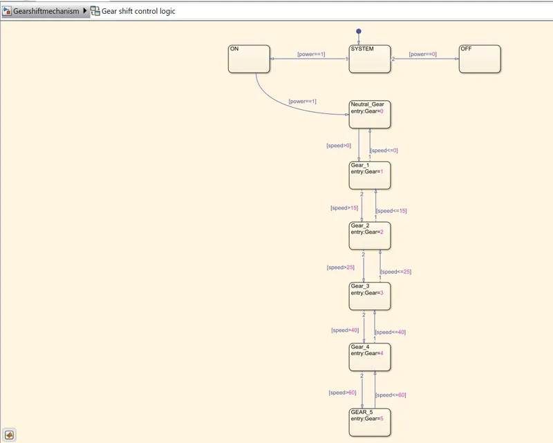
In this State flow model, we have two State inputs named Power and Speed which are connected with a System state and Transition line.
- The system has two conditions ON & OFF indicated as Ipower==1] and [power= =0} respectively.
- If the system is ON then the process will start
- During the initial stage, the system will be in Neutral Gear.
- Once the speed is increased from 0 to 15 kmph then Neutral Gear will shift to Gear 1.
- If the speed is increased from 16 to 25 kmph then Gear I will shift to Gear 2.
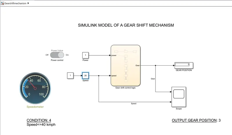
- Similarly, for 26 to 40 kmph then Gear 2 will shift to Gear 3.
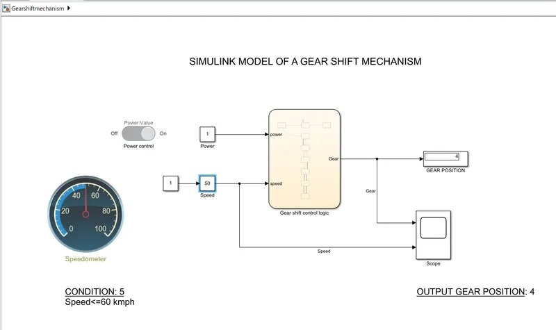
- For 40 to 60 kmph, Gear 3 will shift to Gear 4
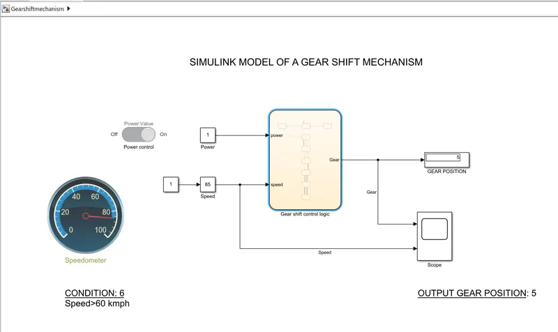
- If the speed is above 60 kmph then Gear 4 will shift to Gear 5.
- During this process, if the speed decreases based on the conditions it will shift its Gear either it will move to the next one or it will move to the previous one.
INPUT AND OUTPUT PORTS:
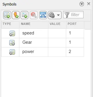
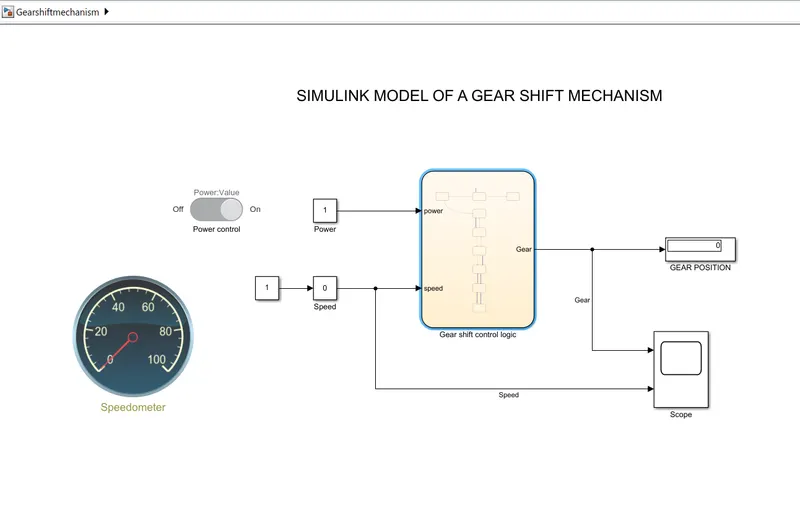
The input ports are connected to the power supply and the speedometer which varies the input speed of the system.
CONSTRUCTION AND WORKING
- In this Simulink model, we created a State flow Chart having all the conditions required to change gears based on the speed.
- Here, in the state flow chart, we have two inputs Power Supply and Speed
- On the output side, we have a gear display.
- A speedometer is connected with a Constant Power block which shows the change of the speed with help of a slider block.
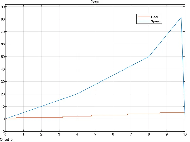
- At Output, we have a Display that helps to show the gear number from 0 to 5. The Scope shows the graphs for the change of speed to the movement in the gear position.
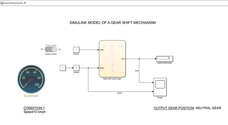
CONDITION:1
Speed=0; Neutral Gear
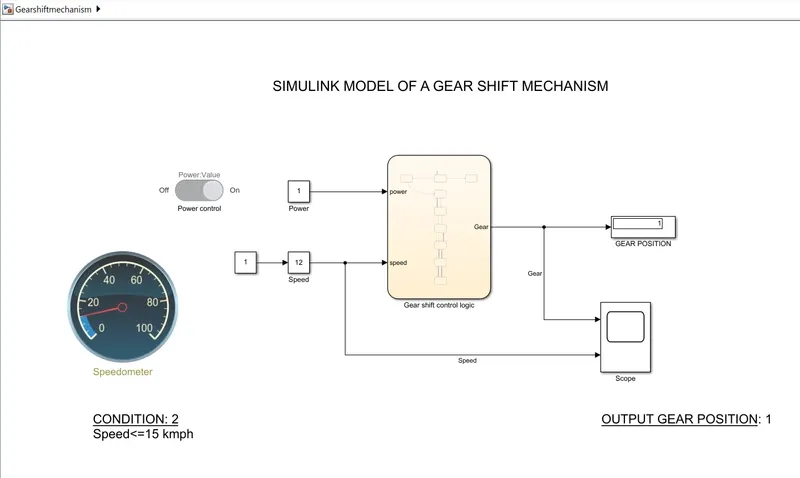
CONDITION:2
Speed<=15kmph; Gear:1
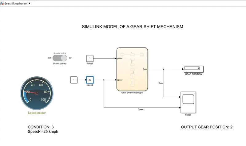
CONDITION:3
Speed<=25kmph; Gear:2
CONDITION:4
Speed<=40kmph; Gear:3
CONDITION:5
Speed<=60kmph; Gear:4
CONDITION:6
Speed>60kmph; Gear:5
COMPARING THE INPUT AND OUTPUTS BY USING SCOPE BLOCK:
When the speed is proportional to the gear position by analyzing the below input data.
RESULTS:
The state flow logic has been implemented and used in the simulation operation to analyze the behavior of the automatic washing machine and Gear shiffting mechanism.