Week - 4
Week 4
1. Implementation of control logic of a washing machine using MATLAB Simulink Stateflow
A washing machine is an electronic device that is used to wash clothes. Earlier generations of this device had a tub whose base was a free-rotating plate designed connected to a unidirectional motor. The tub would be filled with water according to the amount of clothes to be washed, by the user. Later models incorporated a separate spinning tub which used centrifugal force of the spinning clothes to extract water out of them. Modern day washing machines are complex devices that incorporate soaking, washing, rinsing, drying/spinning into a single tub. These devices use complex fuzzy control logic which allows it to automatically select the amount of water required and control the water inlet as per the weight of clothes to be washed. There are even more sophisticated washing machines which can detect the hardness of water, select detergent based on user inputted clothes type and heating the water used for soaking and washing.
The Simulink model with Stateflow is as follows
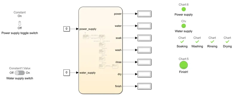
Explanation:
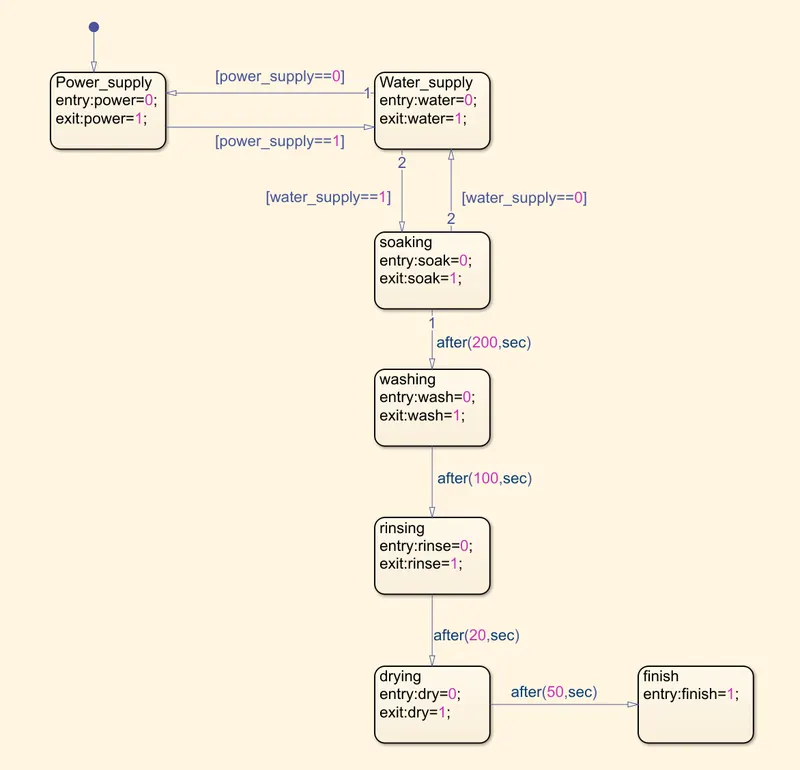
Stateflow-
As per the given question, the control logic only moves to the next state if initial power supply is provided. Therefore, in the Stateflow chart, first block represents the Power Supply to the machine. If Power Supply is available, it moves to check if Water Supply is provided. If this condition is true (water is supplied), it moves to the next consecutive steps i.e. soaking, washing, rinsing and drying before reaching ‘Finish’ block. To simulate the time required for each operation as given in the problem, after(xx ,unit) command is used. Once Drying operation is done, the logic flows to the ‘Finish’ block and stops.
Simulink-
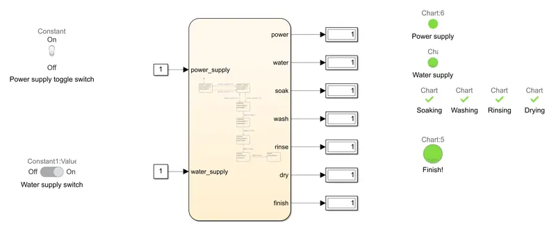
The above Stateflow block takes in 2 inputs; ‘power_supply’ and ‘water_supply’ from 2 constant blocks whose value can be changed between ‘0’ (OFF) and ‘1’ (ON) by a Toggle switch and a Slider switch respectively. The Stateflow block outputs the conditions of ‘power’ (Power Supply), ‘water’ (Water Supply), ‘soak’ (Soaking operation), ‘wash’ (Washing), ‘rinse’ (Rinsing), ‘dry’ (Drying) and ‘finish’. All the outputs are then connected to individual displays. Next, Lamp blocks are connected to each display output which glows green when output is 1 (ON) and red when output is 0 (OFF).
Result:
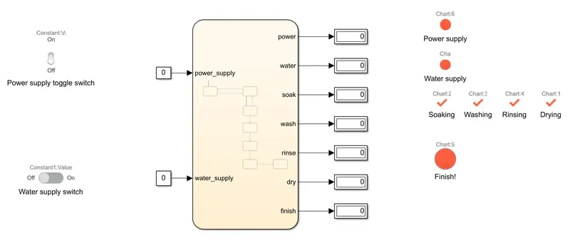
When power supply is off, the lamps glow red. When water supply is turned on, lamps still show red because without power supply, the machine cannot detect water supply (logic is constructed that way).
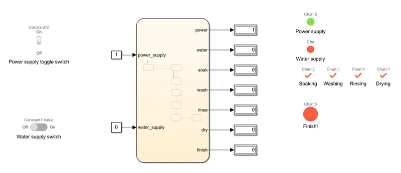
When power supply is on and water supply is off, only ‘Power Supply’ lamp glows green.
When both Power Supply and Water Supply are switched on, the simulation runs till Finish, completing all operations in sequence.
Simulink model:
https://drive.google.com/file/d/1C50peyWBU6PXJh7kUHNUVzATQbJ8e0zI/view?usp=sharing
2. Implementation of control logic of a gear box using MATLAB Simulink Stateflow
ICE vehicles have a narrow band of power and torque which requires a set of gears to reduce/increase the vehicle speed w.r.t. engine speed. Motion from standstill condition requires high torque, but lower power from the engine; here, the 1st gear (which has high number of teeth) helps provide the initial high torque to the wheels. At higher speeds, less torque is required but power required is more. Hence, an overdrive gear (5th gear in this case) which has low number of teeth and can spin faster than the engine speed helps a vehicle maintain its drivability. The gears in between the 1st and overdrive gear helps maximise the usability of a vehicle in different scenarios while keeping the engine speed in its optimal operating range.
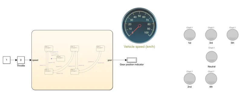
Simulink model of a 5 speed gearbox is as follows
Explanation:
Stateflow-
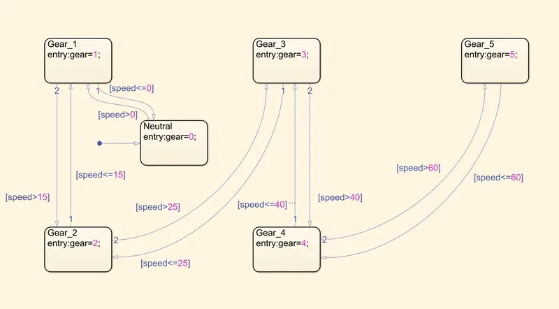
Starting from standstill conditions where ‘speed=0’, the control logic starts at the ‘Neutral’ block. This condition is only returned true when the vehicle is stationary.
Once the speed increases to more than 0, logic flows to ‘Gear_1’. Next, the logic flows to ‘Gear_2’ when vehicle speed increases to more than 15. Similarly, all the gear blocks are defined and their logics mapped to the chart given in the problem. A return logic is also specified for every gear block from 1 through 4.
Simulink-
The above Stateflow model takes in 1 input i.e. vehicle speed, and returns the gear output through a display. The vehicle speed input is simulated by a Constant block with a Slider Gain to act as a throttle control. A Circular Gauge is connected to the Throttle input to indicate the vehicle speed.
A set of lamps are then connected to the Gear Position indicator display output, where they light up in green colour depending on which gear is selected by the control logic.
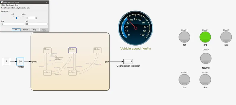
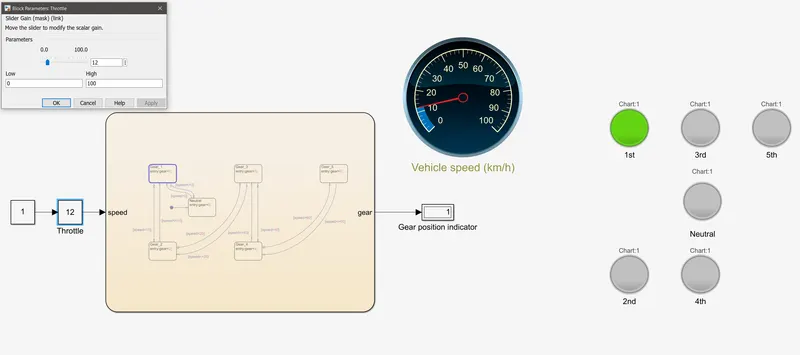
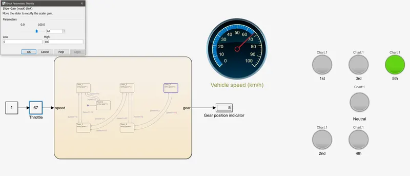
With the simulation stop time specified as ‘inf’, to run till the user stops it, the Throttle is changed by the slider and it is seen that the gear changes according to the conditions specified in the problem.
Results:
At 35kph, the following results were found
At 12kph, the following results were found
At 67kph, the following results were found
Simulink model:
https://drive.google.com/file/d/1w8DdNVv9CGc6oJ8E-Wqp3QbEG49nqvh4/view?usp=sharing