Week - 4
Aim: To create Simulink model of a Washing machine control logic and vehicle gear shifting logic using stateflow as per given conditions.
- Washing Machine
Theory: A washing machine is a device that cleans unclean cloths. It has a barrel that the items are placed in. This barrel is filled with water and circulated rapidly to remove dirt from the clothes. The majority of washing machines are designed to receive detergent (liquids or powders). These might assist in the cleaning of the clothes.The main parts of a typical washing machine is shown in figure (1).
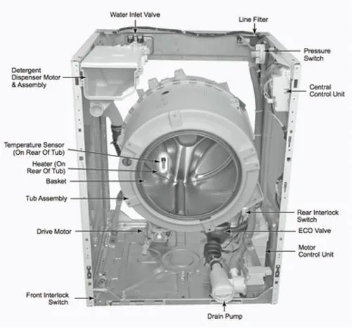
Figure (1) Parts of washing machines
There are controls on washing machines that show exactly how they work. The following are a few examples of possible controls:
Wash cycle timeframe for cycles (soaking time, drying time).
The number of wash cycles required for different cleaning modes.
Temperature levels of water.
There are several types of washing machines available on market some of them are Front-Loading, Washer and Dryer Combo, Integrated, Stackable, Portable or Compact, Top-Loading, Semi-Automatic and Fully-Automatic Washing Machines.
Simulink Model: The figure (2) shows the Washing machine Simulink model, washing stateflow is the name of chart and it is in figure (3). The Simulink model contains constant, chart and display blocks and its purpose and usage is listed below.
Conditions:
- When the power supply is on, system gets started.
- When the water supply is closed, stop the process and indicate.
- Soaking time 200 seconds and Washing time 100 seconds.
- Rinsing time 20 seconds and drying time 50 seconds.
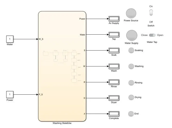
Figure (2) Washing Machine simulink model
Constant blocks: The water and power supplies are represented with constant blocks. If the value is one which means supply is available and zero means non availability of sources.
Chart block: The chart block contains stateflow of washing machine working cycle. The first state is input, the water and power supply variables W
_S and P_S given as output type datas in chart. The availability of these sources are checked in the next two states, if the values are zero it is routed to junction for terminating process. When the sources are available or conditions satisfy, then stateflow moves to starting of cycles. The soaking process starts and its variable named as S and it conditions, time all is mentioned in the state. Similarly washing, rinsing and drying process variable conditions, timings are mentions in corresponding states. The data variables in each state are output type data with initial value as 0. Finally process completion state is activated.
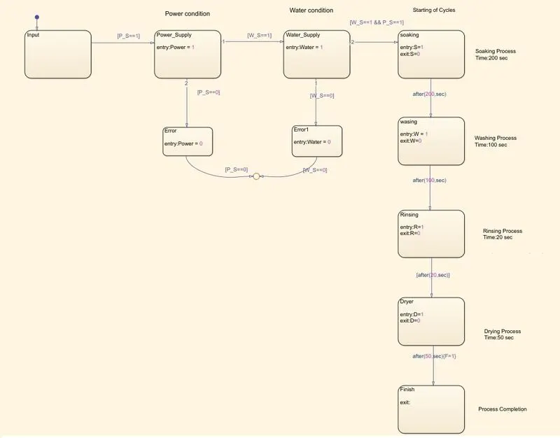
Figure(3) washing stateflow
Display block: To understand which process is going on and to check the working display blocks are implemented. By looking into values can understand the process.
Indicators: Lamps, toggle switch and slider switches are for indicating sources and process on going in a washing machine. Each lamp has heading to understand the cycle and source moreover, toggle switch represents power supply switch and slider switch indicates water tap.
The below figure (4) shows indicator panel working of a washing machine a complete cycle. When the process completes the end lamp will light in yellow colour.
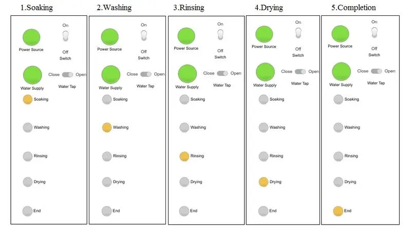
Figure (4) Indicators Working
The error situations are shown in figure (5).If there is short any supplies the red led on corresponding source will blink in red.
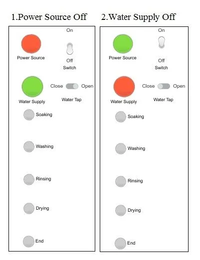
Figure (5) Error conditions
- Gear shifting
Theory: A gearbox is a mechanical device that increases the output torque of a motor or changes its speed (RPM). The transmission's role is to deliver high torque when starting, hill climbing, accelerating, and pulling a load. High torque is required at the driving wheels when a vehicle starts from a rest, climbs a slope, accelerates, or encounters other resistance.
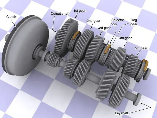
Figure (a) Gear box image
As a result, a device is required to allow the engine crankshaft to rotate at a reasonably high speed while the wheels rotate at a slower rate. This is contained within a gearbox, which is a metal box. The transmission can also adjust the vehicle's speed while keeping the engine speed within a specific range. There are four type of transmission system available which are listed below.
- Manual Transmission (MT)
- Automatic Transmission (AT)
- Automated Manual Transmission (AMT)
- Continuously Variable Transmission (CVT)
A manual transmission, often known as a stick-shift unit, is a gearbox that requires the driver to move the gears manually. To regulate the torque from the engine to the wheels, the driver must engage the clutch by pressing/depressing the foot pedal and select an appropriate gear ratio by using the gear-selector lever.
An automatic gearbox, as the name implies, is a self-shifting transmission that eliminates the need for the driver to shift gears manually.
An AMT, often known as an auto gear-shift transmission, is a type of automated manual transmission. It's nothing more than a manual transmission.
A CVT, or continuously variable transmission, is an automated gearbox that fluidly moves across a continuous range of gear ratios. It is also known as a pulley transmission or a step-less transmission. A CVT, on the other hand, offers almost endless gear ratios that can be changed on-the-fly to provide a fluid driving experience.
Simulink Model: The Simulink model of gear shifting logic is given in figure (b).
Conditions:
| speed (kmph) | 0-15 | 16-25 | 26-40 | 41-60 | 61-above |
| Gear Number | 1 | 2 | 3 | 4 | 5 |
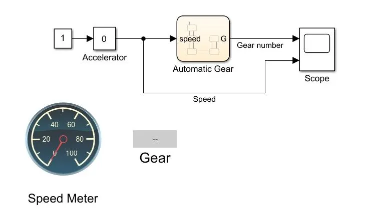
Figure (b) Simulink model of gear shift
Slider Gain and constant block: It acts as accelerator of automobile. Can give input during simulation with slider gain block. The parameters of slider gain given as 0 to 100, these are the speed limits of vehicle.
Chart: The gear shifting logic is implemented in chart named automatic gear the input is speed and output is gear number (G).The stateflow is shown in figure (c).
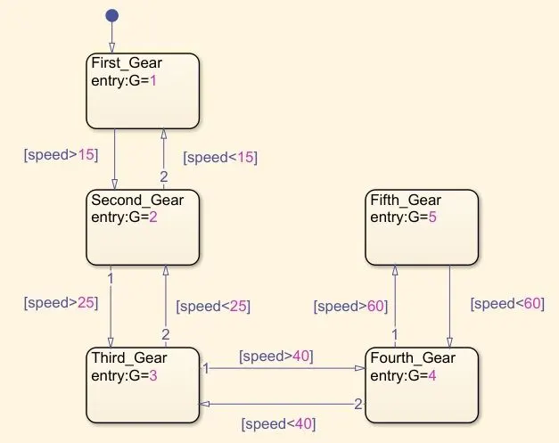
Figure (c) Stateflow of gear shift logic
The speed variable taken as input and given conditions to change the gear number. When the speed greater than 15 kmph G=2, when it reaches below 15 kmph G=1. Similarly speed conditions and gear number is applied till fifth gear in the states.
Scope: To plot speed and gear number graph and it is in figure (d). By looking at the graph ensured the gear shifting logic of vehicle is correct as per conditions.
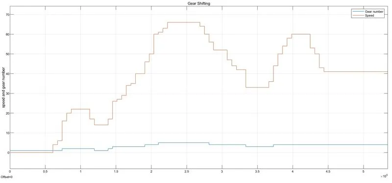
Fugure (d) Graph of speed vs gear number
Indicators: Custom gauge for speedometer and display for gear number blocks are used. The blocks connected to corresponding blocks and signals. The display of different speed and corresponding gear number are shown in figure (e).
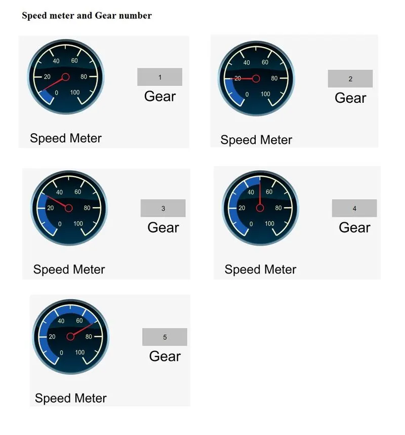
Figure (e) Indicating Gear number at various speeds
Conclusion: The Simulink models are created according to the conditions moreover, studied about stateflow and its implementation in various applications.