Week -2
Aim: To create Simulink models of Doorbell using solenoid and Heater with a thermistor to sense the temperature to perform operations under given conditions.
Doorbell
Theory: Doorbell consists of several parts such as battery, switch, Electromagnet, spring and hammer as shown in figure (1). The main part of the bell system is electromagnet or solenoid. Electromagnets are coils taped around a metal, when electricity passes it creates magnetic field around the coil.
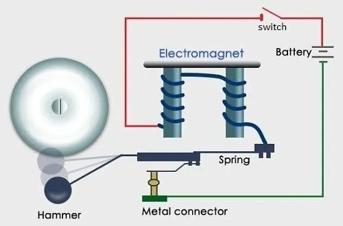
Figure (1) Doorbell
When a doorbell switch is pressed, an electrical circuit is completed, allowing household electricity to flow via the doorbell's internal electromagnet. The electromagnet's magnetic field is then employed to power a hammer to hit the plate.
Simulink Model: Simulink model of a Doorbell using solenoid block is given below figure (2).
Conditions:
- When the switch is closed, the electromagnet gets the electricity from the battery and drives the metal arm, causing the bell to ring.
- Set up a scenario in which the switch is closed for two seconds and then released. Examine the plunger's physical movement.
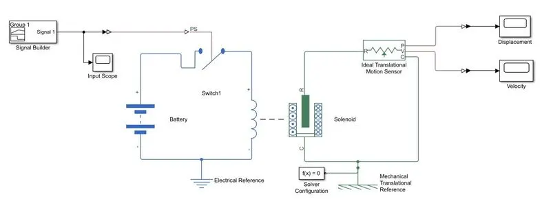
Figure (2) Simulink model of Doorbell
The Model contains input and output units which are specified in the below diagram.
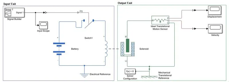
Figure (3) Simulink doorbell model explantion
Input Unit:
- Signal builder creates input pulses under mentioned conditions.
- Input scope is for plotting input signal from signal builder.
- Simulink-PS converter used for converting signal to physical state.
- Switch block is for performing on and off operations. When signal is above threshold value the switch activates the circuit.
- Battery is the power source for doorbell system.
- Electrical reference block is to provide ground or earth to electrical circuit.
- Coil or inductor in the Solenoid block will create the magnetic field if the switch is closed.
Output Unit:
- Due to mutual induction solenoid metal part activates.
- Solver configuration provides settings for simulations.
- Mechanical reference is to ground the mechanical parts.
- Ideal translational motion sensor used to sense the translational or linear motion on the solenoid. P and V output ports provide displacement and velocity values.
- PS-Simulink convertors are used to transforming signals to output Simulink signals.
- Displacement and velocity scopes are used to plot the graphs with respect to time.
Working: The required input signal is created by Signal builder, switch is close and open for two seconds, for this condition a square wave is created as shown figure (4). First 2 seconds switch is closed and the solenoid will show some movement. The motion is detected by ideal translational motion sensor. The next 2 seconds which would be open and no current passes through circuit hence no motions in the solenoid.
Signals: Input and output signals appeared on scope blocks are shown below.
Input signal: The signal value is one for first 2 seconds and off for next 2 seconds and continues same pattern. The conditions given satisfy the input wave.
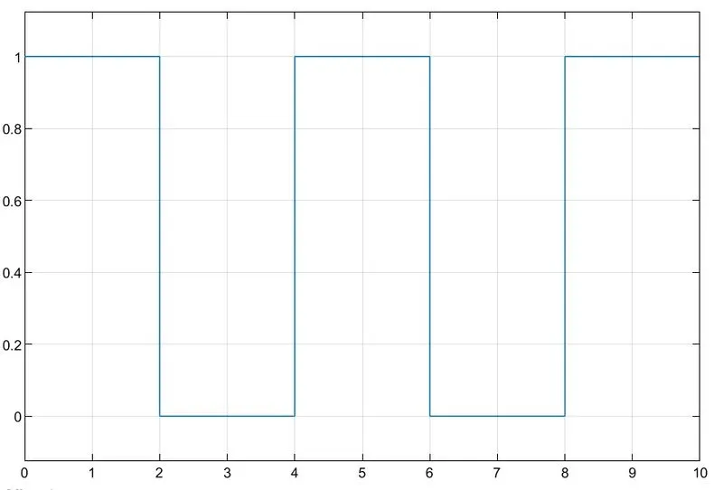
Figure (4) Input signal of Doorbell
Output signals: The Bell made sound and silenced alternatively for two seconds. The displacement showing the movement of plunger in the first 2 seconds returns to zero in next 2 seconds. The below figure (5) shows the output from Ideal Translational Motion Sensor.
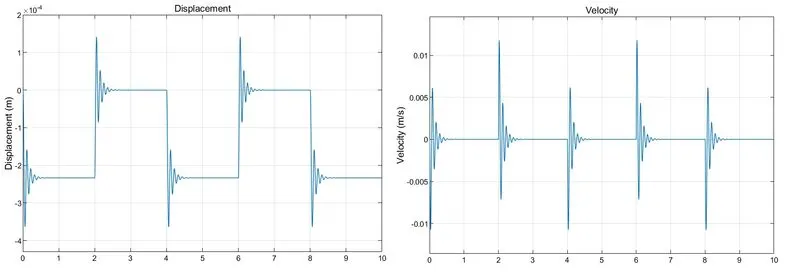
Figure (5) Output signals of Doorbell
Heater
Theory: A heater is a piece of equipment or a mechanism that increases the temperature of something, most commonly the air inside a room or a vehicle. The conversion of electrical energy to heat energy is known as electric heating. Space heating, cooking, water heating, and industrial activities are all common uses. An electric heater is a device that transforms a current of electricity into heat.
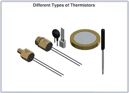
Figure (a) Thermistor
A thermistor is a type of resistor with a resistance that is more temperature dependent than normal resistors. The term is derived from the words thermal and resistor. There are two types of thermistors PTC and NTC.
Resistance increases as temperature raises in PTC thermistors, owing to increasing thermal lattice agitations, particularly those caused by impurities and defects. PTC thermistors are often employed as resettable fuses in series with a circuit to guard against overcurrent circumstances.
Resistance drops as temperature rises in NTC thermistors, owing to an increase of conduction electrons bumped up by thermal agitation from the valence band. An NTC is typically employed as a temperature sensor or as an inrush current limiter in series with a circuit.
Simulink Model: Simulink model of a heater motor or fan controlled using thermistor is given in below figure (b).
Conditions:
- Temperature input: 20 °C from 0 to 10 seconds, 27 °C from 10 to 30 seconds, 23 °C from 30 to 50 seconds.
- Fan conditions: ON if the temperature above 25 °C, OFF otherwise.
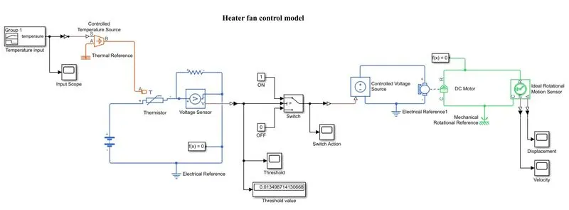
Figure (b) Simulink model of heater fan control
The model divided into several sections for ease of explanation and it is given in figure (c).
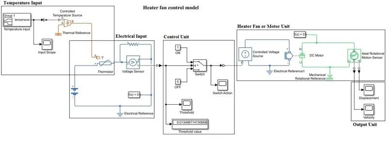
Figure (c) Heater model explanation
Temperature input:
- Signal builder creates input temperature under mentioned conditions.
- Input scope is for plotting input signal from signal builder.
- Simulink-PS converter used for converting signal to physical state.
- Controlled Temperature Source block provide the energy source to thermal network. Port S is connected to temperature signal, port A to Thermal reference and port B to Thermistor.
Electrical Input:
- Thermistor block represents NTC type thermistor, the temperature input depends on the current flowing through it.
- Battery is the power source for doorbell system.
- Electrical reference block is to provide ground or earth to electrical circuit.
- Solver configuration provides settings for simulations.
- Resistor is a electrical component, which is used to measure voltage across it.
- Voltage Sensor is to measure the voltage across resistor and connected parallel in the circuit. The port V output the voltage value.
Control Unit:
- Switch block is to perform switching operations.
- Constant blocks given 0 and 1 to provide on and off functions to switch.
- Scope blocks are used to plot the graphs.
- Display block to identify Threshold value.
- Corresponding signal convertors are used.
Heater fan unit:
- Controlled voltage source block as the name indicates it provide constant voltage regardless of the current.
- Dc motor block represents the motor or fan of a heater.
- Ideal rotational motion sensor to sense the motion of the motor.
- Mechanical reference is to ground the mechanical parts.
Output Unit:
- Scopes plot the displacement and velocity with respect to time.
- PS-Simulink convertors are used to transforming signals to output Simulink signals.
Working and plots:
The signal builder creates the required temperature input at specified timings. As shown in input graph which is obtained from input scope and this Simulink signal further converted to physical signal using converters. The controlled Temperature block will provide the temperature input to the Thermistor. Temperature values are given in kelvin.
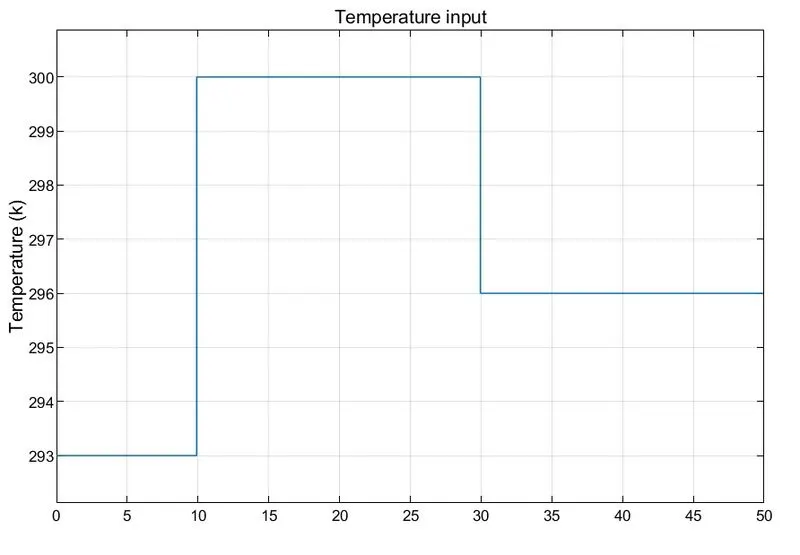
Figure (d) Input scope
The electrical input provides the electricity to run the motor. A voltage sensor is used to measure current. The output of voltage value is connected to control unit.
The control unit perform the controlling action of heater motor. According to the voltage value the switch control the on and off function of motor. Using threshold scope and display the value found 0.01349871430668. This value is given Threshold to the switch block. So switch will be on when reaches value more than threshold. The switch action graph is shown in figure (e) switch is on between 10 to 30 seconds which means objective is satisfied. In the switch action graph 1 means on and 0 means off.
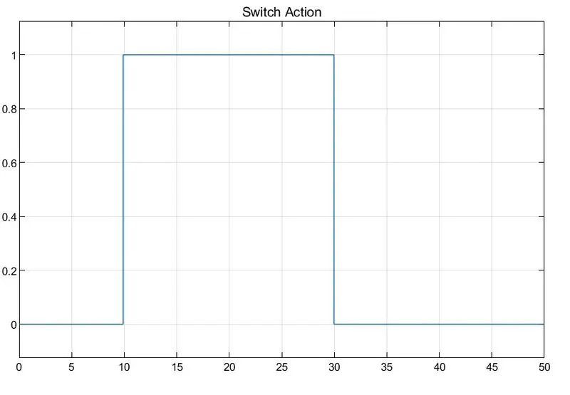
Figure (e) switch action scope
The heater fan unit represents the fan unit of a typical heater. When the switch is on, controlled voltage source provides electricity, the motor rotates and rotaional motion is metered by a sensor.
The output scope plots the graphs of displacement and velocity form the respective ports of ideal rotational motion sensor. From the graphs it is evident that motor is turned on when the temperature reaches only above 25 degree Celsius and off at below this temperature. Heater fan tuned on between 10 to 30 seconds.
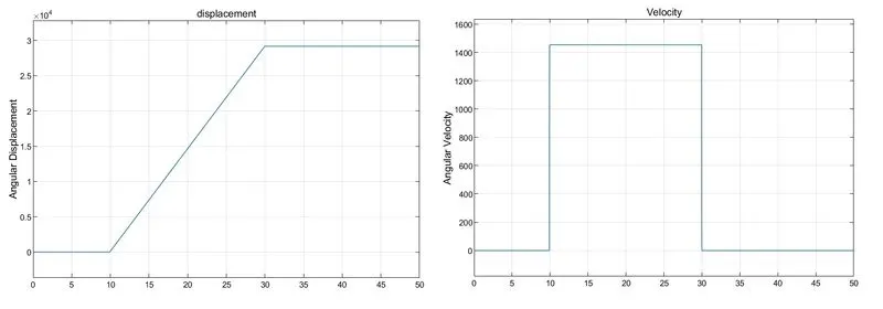
Figure (f) Outputs of Ideal rotational motion sensor
Conclusion: Created Simulink models of Doorbell using solenoid and Heater with a thermistor to sense the temperature moreover, the models are satisfied the given conditions.