Week - 4 - 2D meshing for Plastic components
Week - 4 - 2D meshing for Plastic components
(cap meshing)
Objective
For the given Plastic Bottle Cap model, check for geometrical errors and take the mid surface using suitable mid-surfacing techniques. PID and Thickness assignment must be done for all the mid surfaces. Mesh the same with the given element Quality criteria.
1 . The generated mesh must be exported into Optistruct (.fem) or Radioss (.rad) format.
2. The Mid-surface and the Original Geometry (Parent Component) must be attached as a
CAD file (.iges or .stp).
Target Element Length = 1 Units
|
S.No |
Quality Criteria |
Value |
|
1 |
Target/Average length |
1 |
|
2 |
Minimum Length |
0.5 |
|
3 |
Maximum Length |
3 |
|
4 |
Aspect |
3 |
|
5 |
Warpage |
15 |
|
6 |
Skewness |
45 |
|
7 |
Jacobian |
0.7 |
|
8 |
Minimum Quad Angle |
45 |
|
9 |
Maximum Quad Angle |
135 |
|
10 |
Minimum Tria Angle |
30 |
|
11 |
Maximum Tria Angle |
120 |
|
10 |
Tria Percentage |
15 |
Cad model image: -
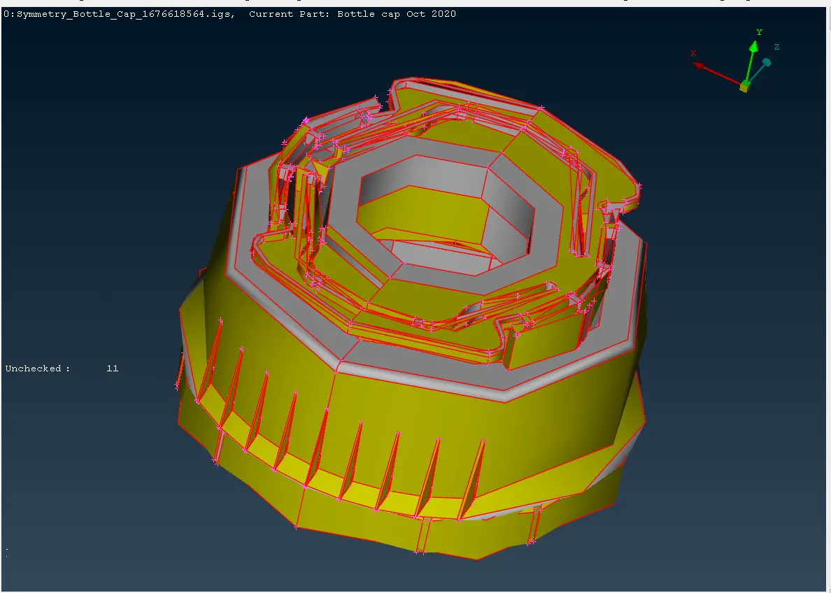
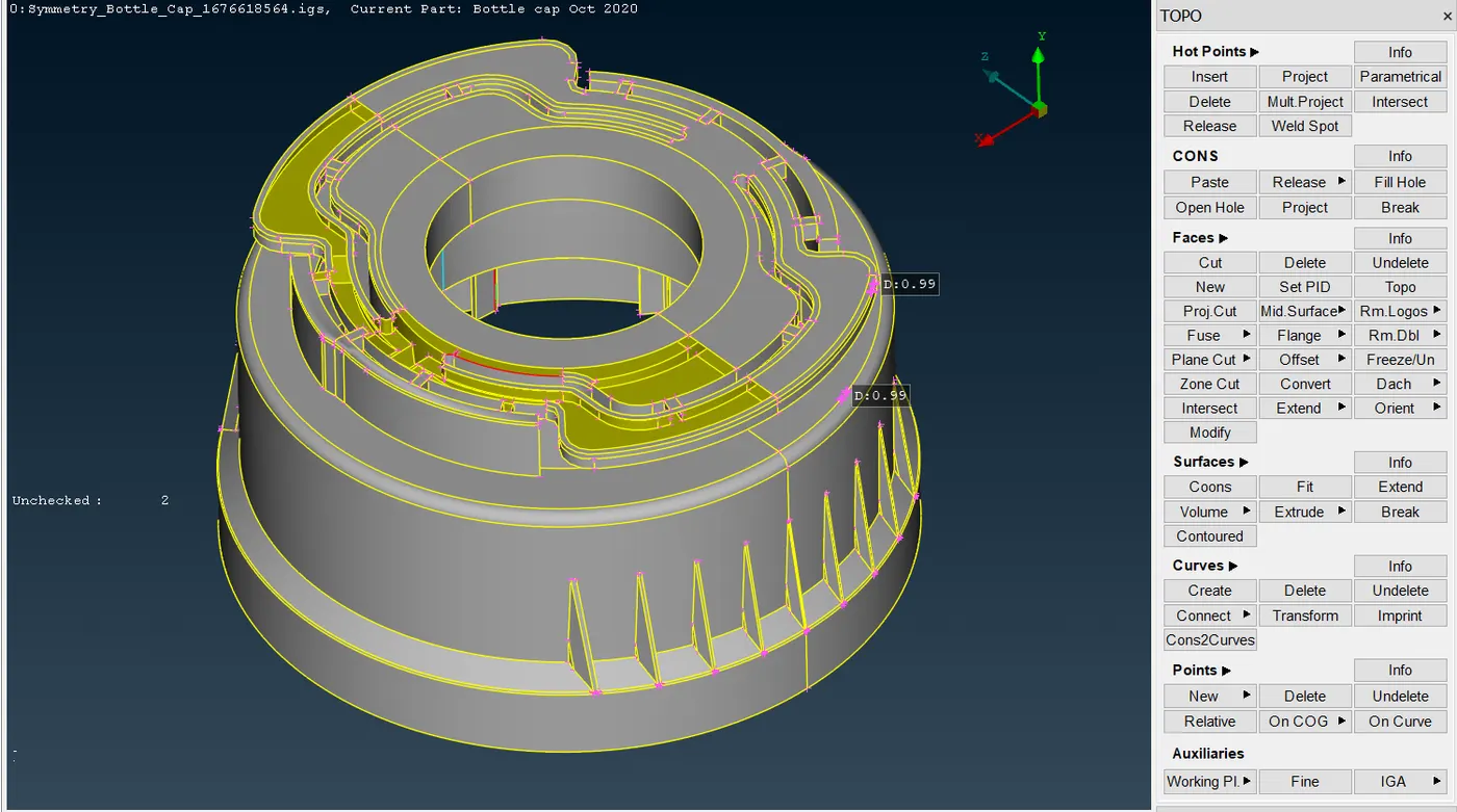
After importing the cad we will set the perimeters and macro length to 1(switch to classic mesh module-in perimeters select length-then choose perimeters to 1 and macro to 1), so that we can geometry can be proper shape.
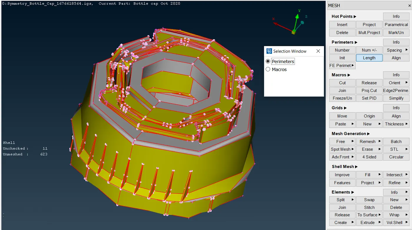
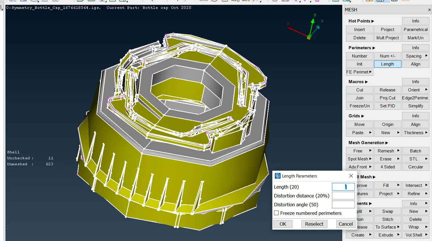
after setting parameters and macro length to 1 result can be seen as follows
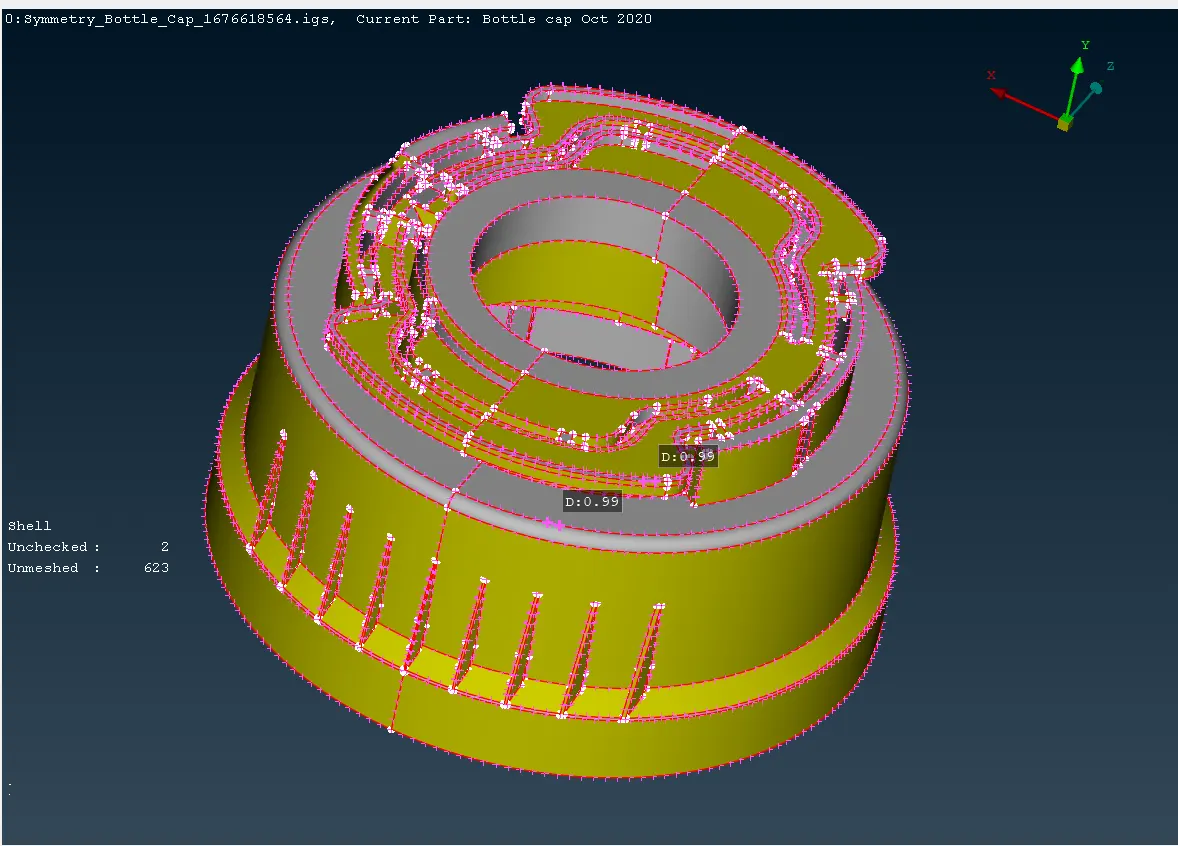
Also make sure surfaces are oriented and given topo properly (Topo module-in faces choose Topo in same faces section orient can be chosen to orient the faces which will useful in the direction of offsetting faces).
· Geometry checks:
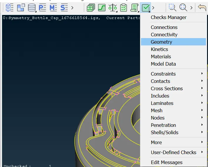
Before going for the modelling process, we should do geometry checks like cracks between surfaces, unnecessary triple cons etc.
This can be done in Ansa using the geometry checks option (geometry checks-choose errors need to hillite - Execute) as follow.
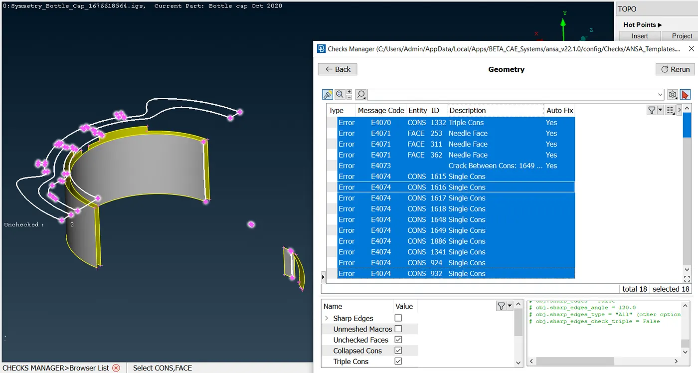
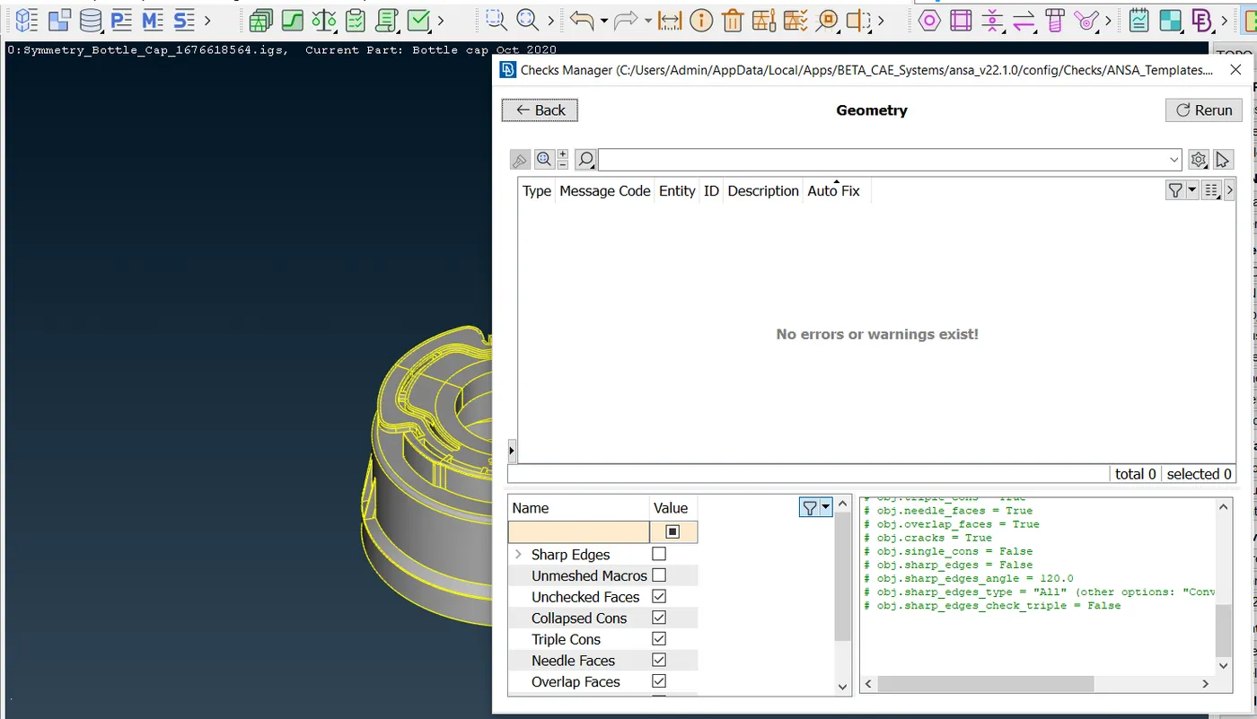
From above picture we can observe that almost errors can be cleared automatically, (fix by Ansa by selecting the errors which showing yes in auto fix column).
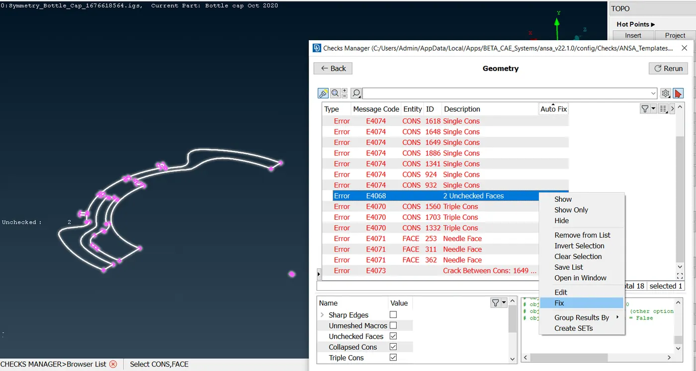
after giving auto fix for the above error e4068 almost all errors which do not have an auto fix option enabled are cleared automatically.
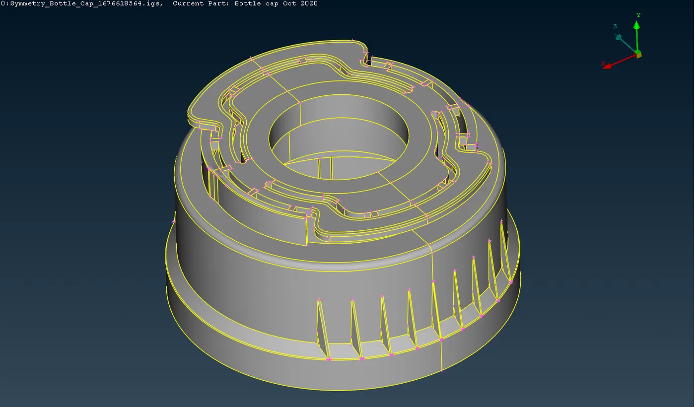
after the geometry cleaning is completed the CAD model finally looks as follows,
Midsurface creation: -
First, we need to check for thickness variations in the component so that we can conform the component is sheet metal or plastic.
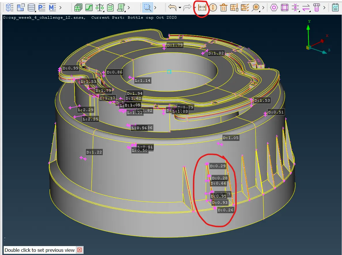
As we can see, there are variations in thickness, so we can conclude that this part is a plastic component.
Here, we will generate the mid-surface from top to bottom. As it is a plastic component, we prefer manual mid-surfacing steps.
by using the "!not" command to isolate top portion as shown below, and also store the view for ease of access
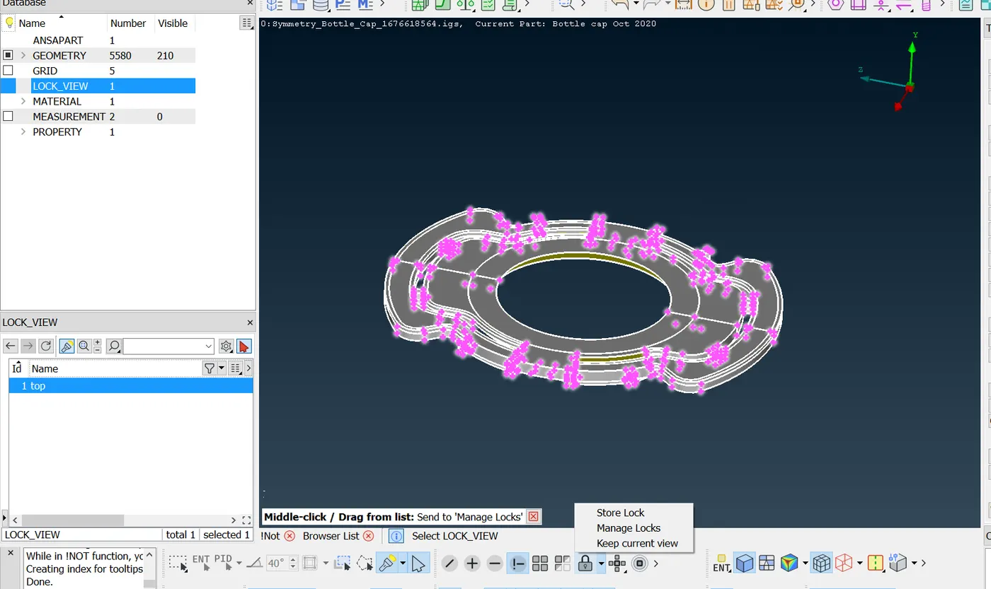
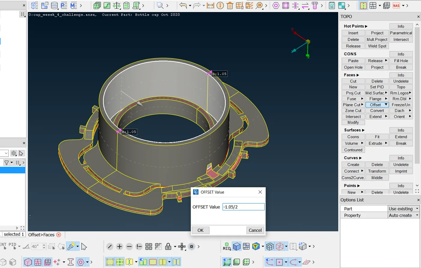
above faces having uniform thickness I have used the faces offset option (TOPO-FACES-OFFCET-SELECT THE ONE SIDE OF FACES TO OFFSET -OK -ENTER VALUE VALUE ACCORDING TO VECTOR SHOWN AS BELOW-GIVE OK TO generate SURFACE).
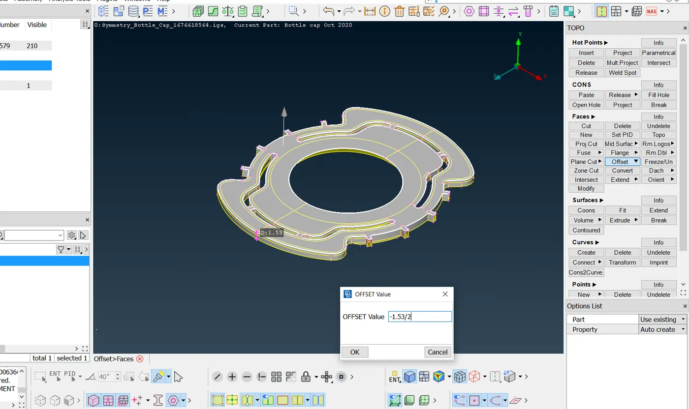
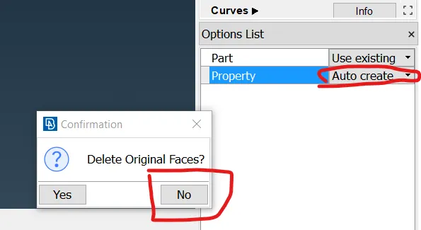
and also make sure the bellow option is selected while extracting surfaces. This will create property newly and choosing no for deleting original faces will stop deleting original surfaces used for extracting mid surface.
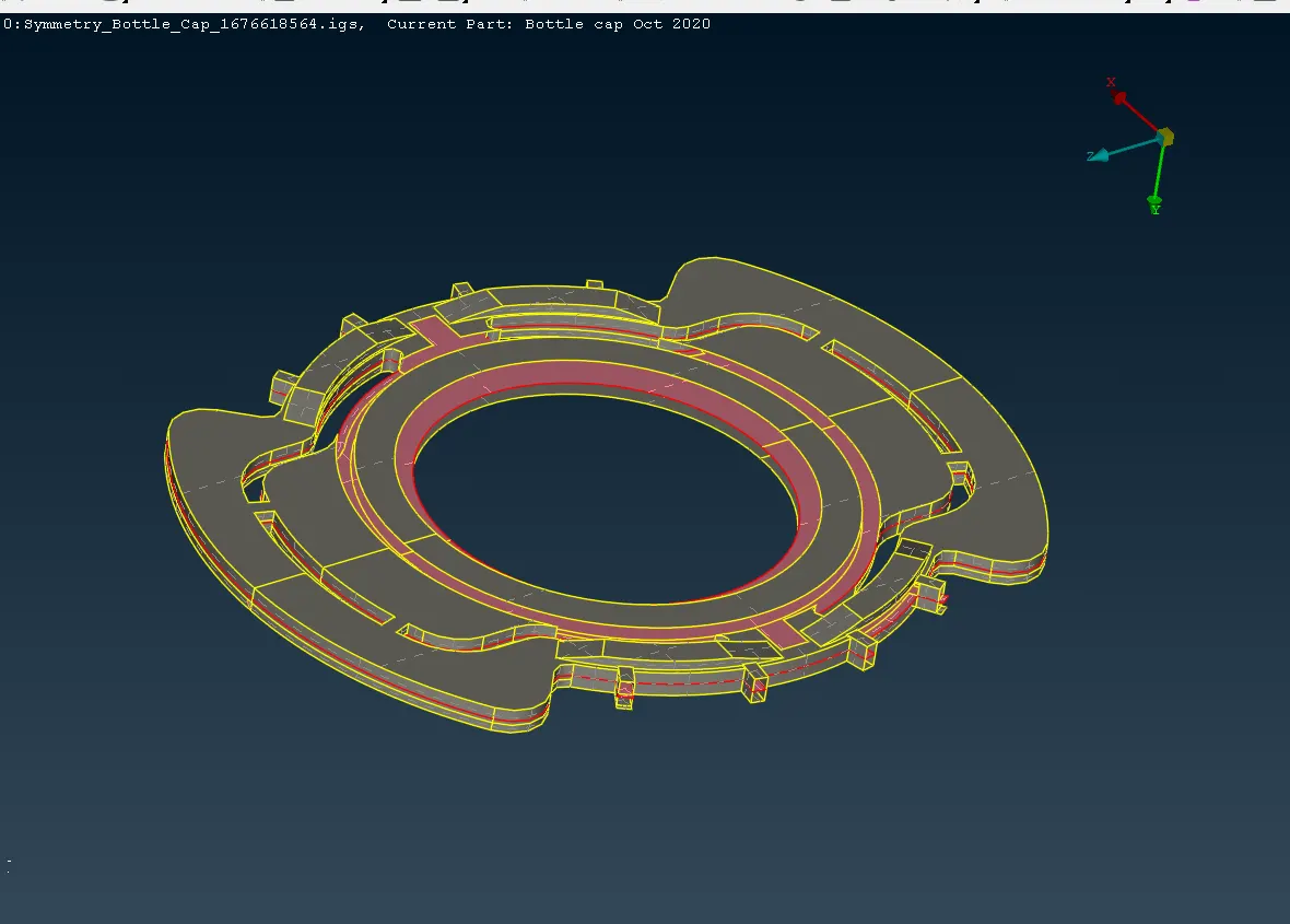
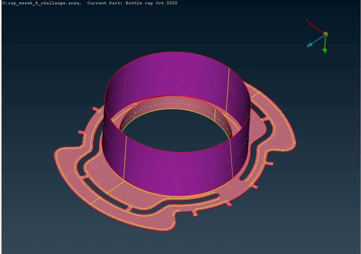
result of offected surface as shown below (red)).
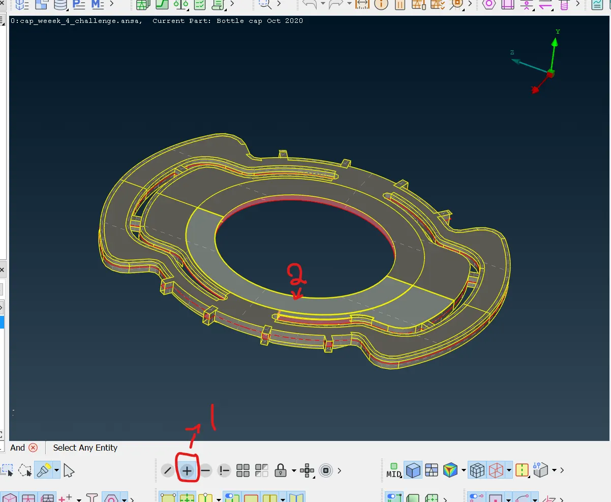
by using neighbour (select '+' icon then sect edge of the surface that needs to show the attached surface)option we can bring adjacent surfaces to extract midd surfaces as shown below.
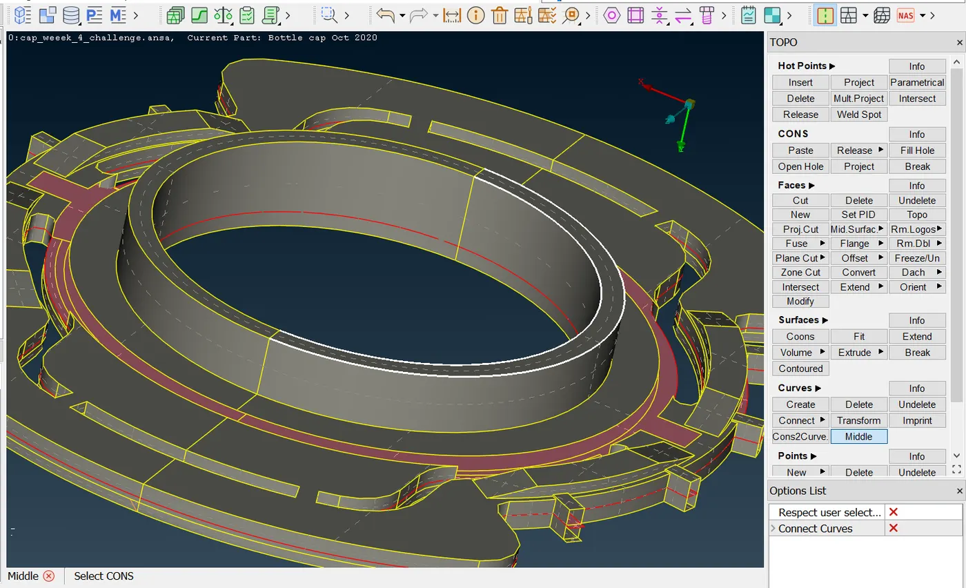
to create midd surface for the above adjacent surface we used the middle curves option (topo-curves-middle-secect the curves-ok) as shown above after that, we used the extrude option (topo-surfaces-extrude-sect the curves-sect the direction of the vector in which surface need to create.)to create a surface using the curves as bellow.
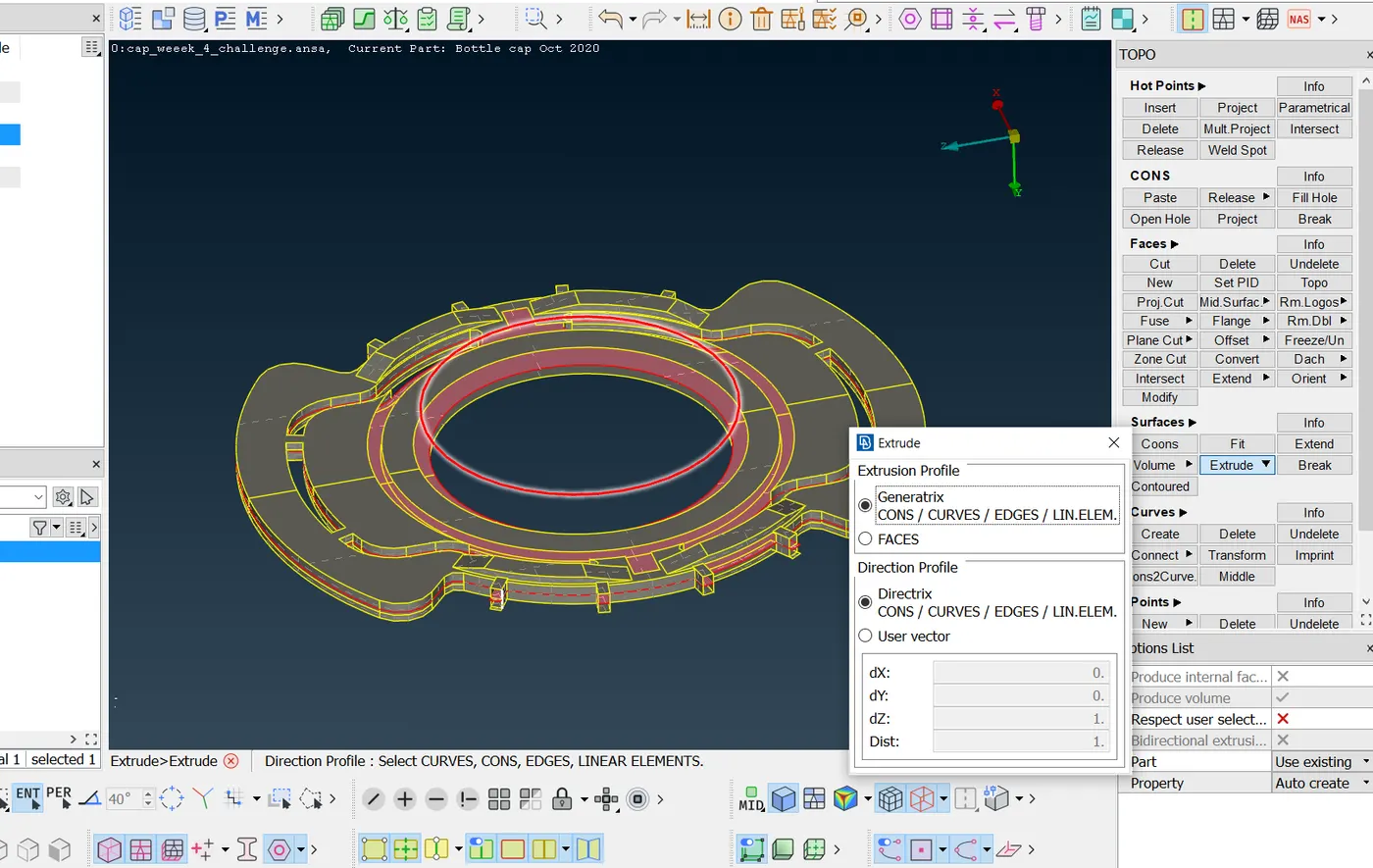
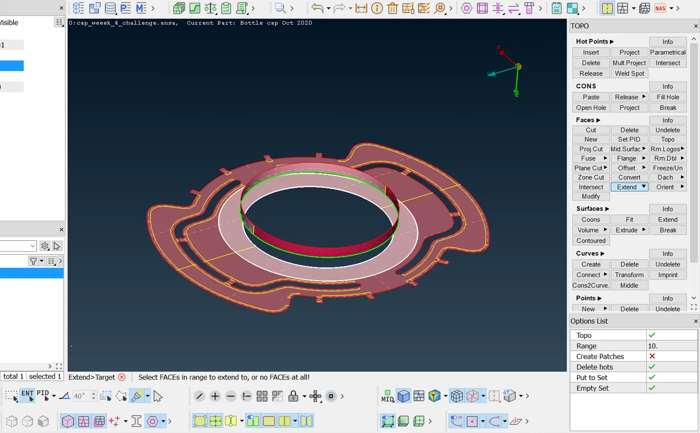
to connect the surface with the bottom surface we used extend option(topo-faces-extend-sect edge the surface to extend-give ok -then select the target surface-ok)used to connect two surfaces.
offcet option is used to create midd surface for bellow as feasure and the connected to base surface as above using extend option.
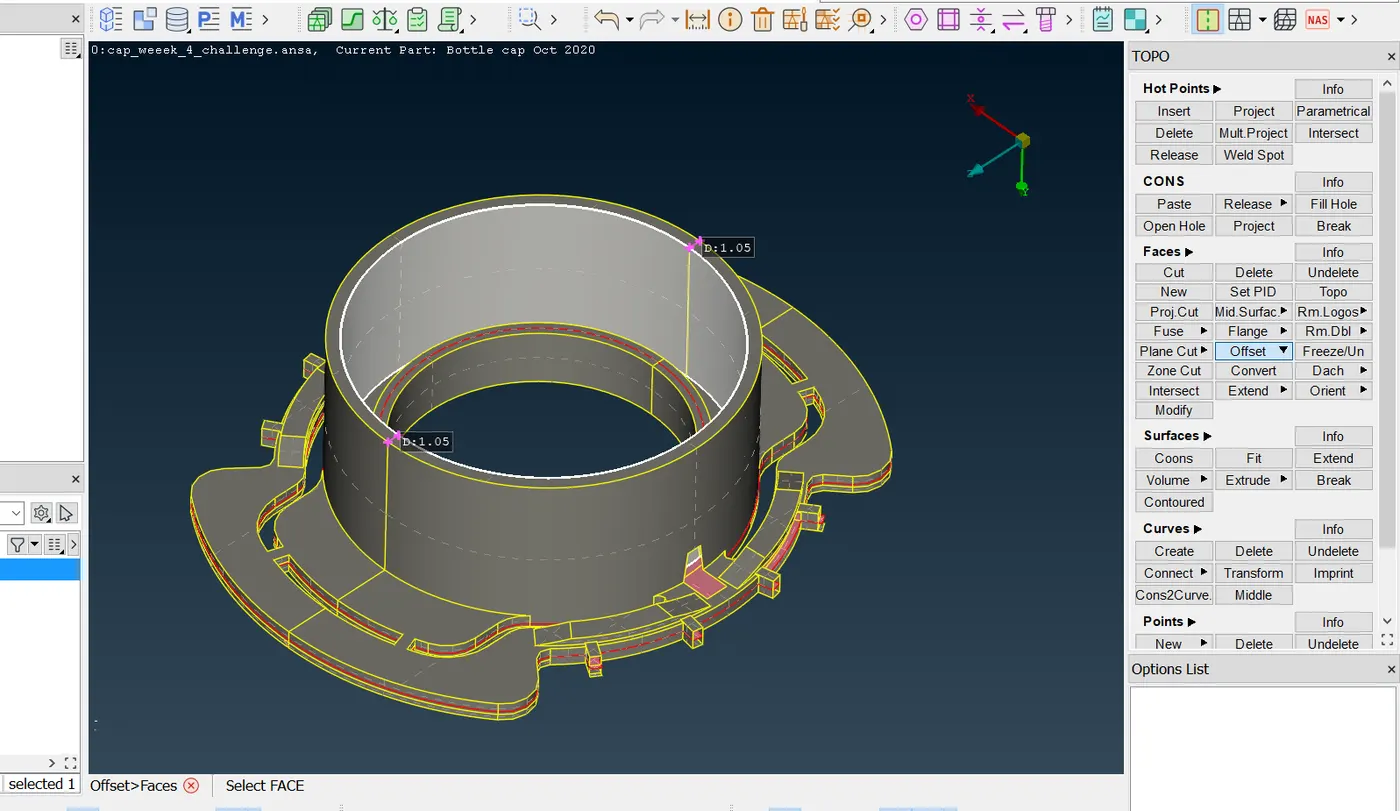
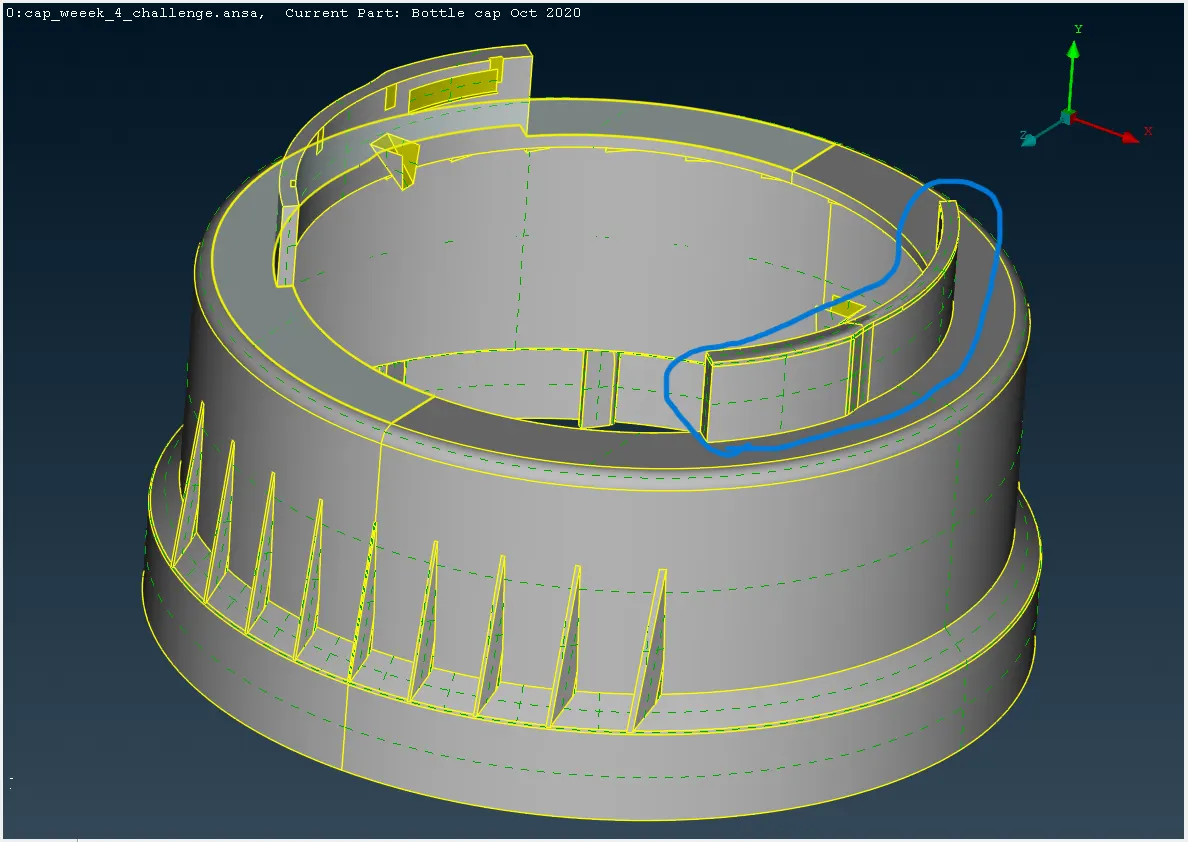
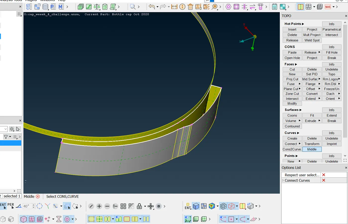
fro bellow feature we extract middle curves top and bottom of the feature to capture the feature. as shown bellow.
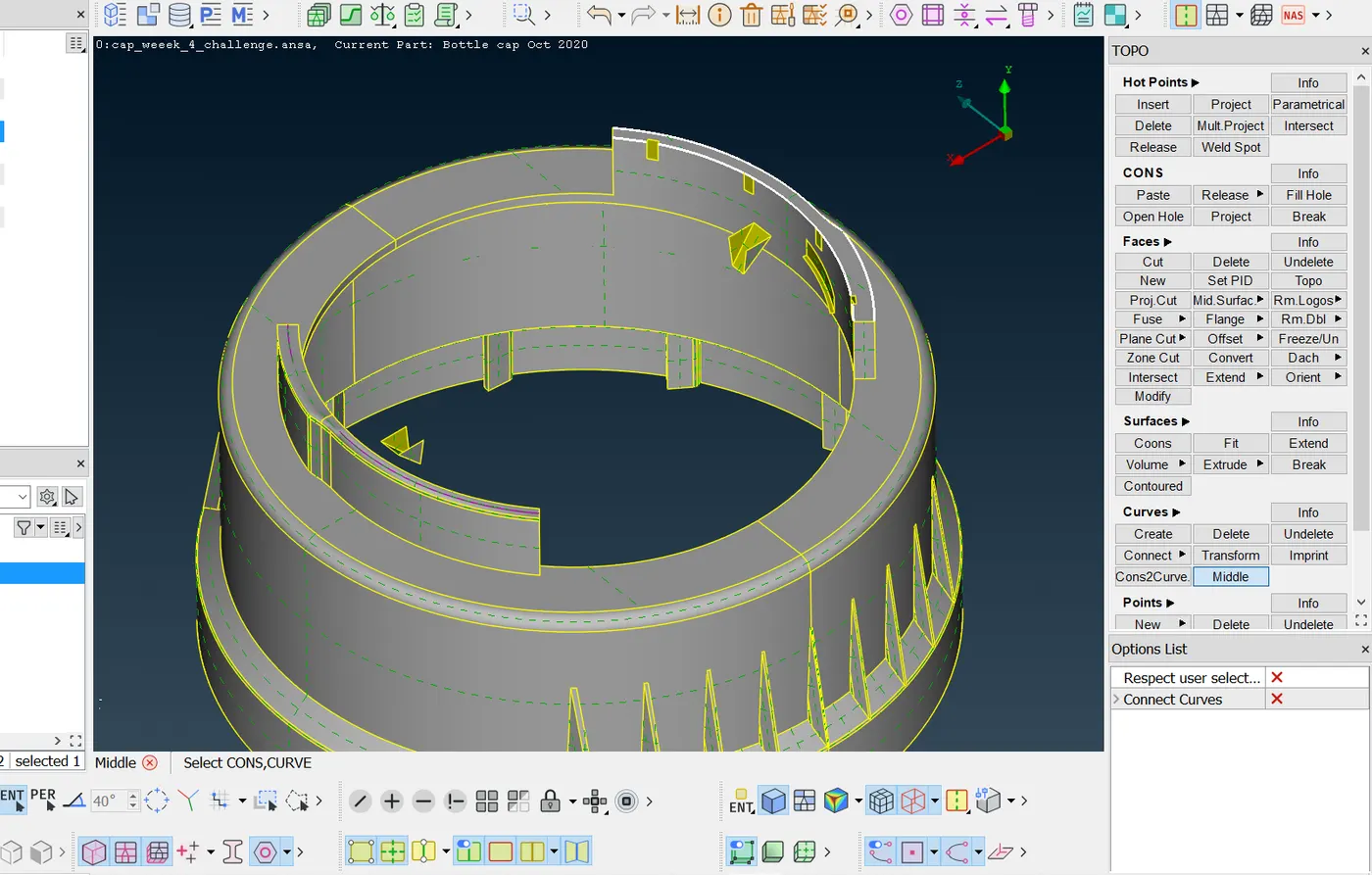
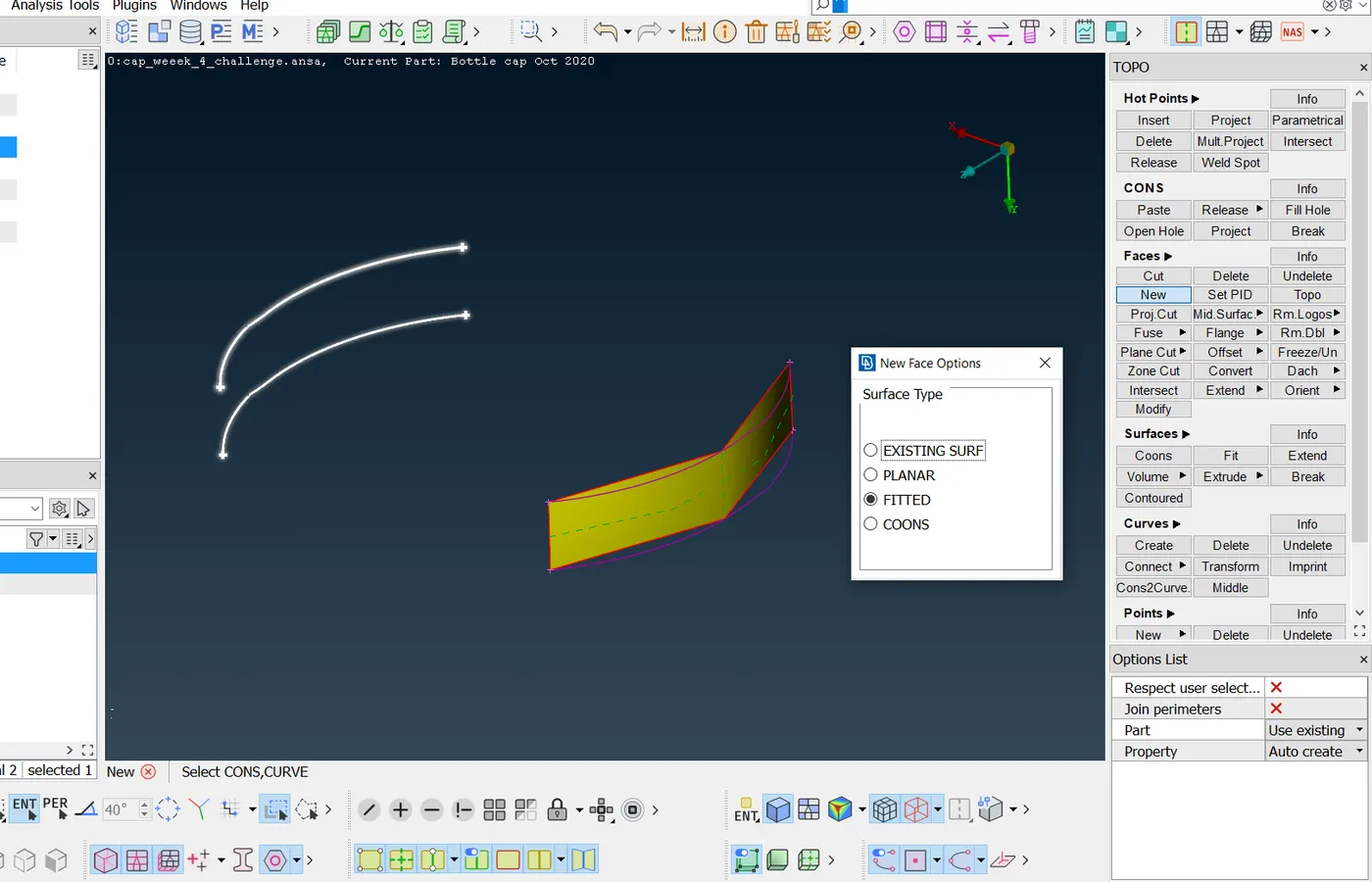
to create the surfaces between the curves (topo-faces-new-fitted-select first set of curves-ok then the second set of curves) option is used as shown below
same extend option is used to connect with base surface which is extracted first.
to extrac the surface for bellow feature first we check for the thickness using weld spot option(topo-hot points-weld spot) as shown bellow
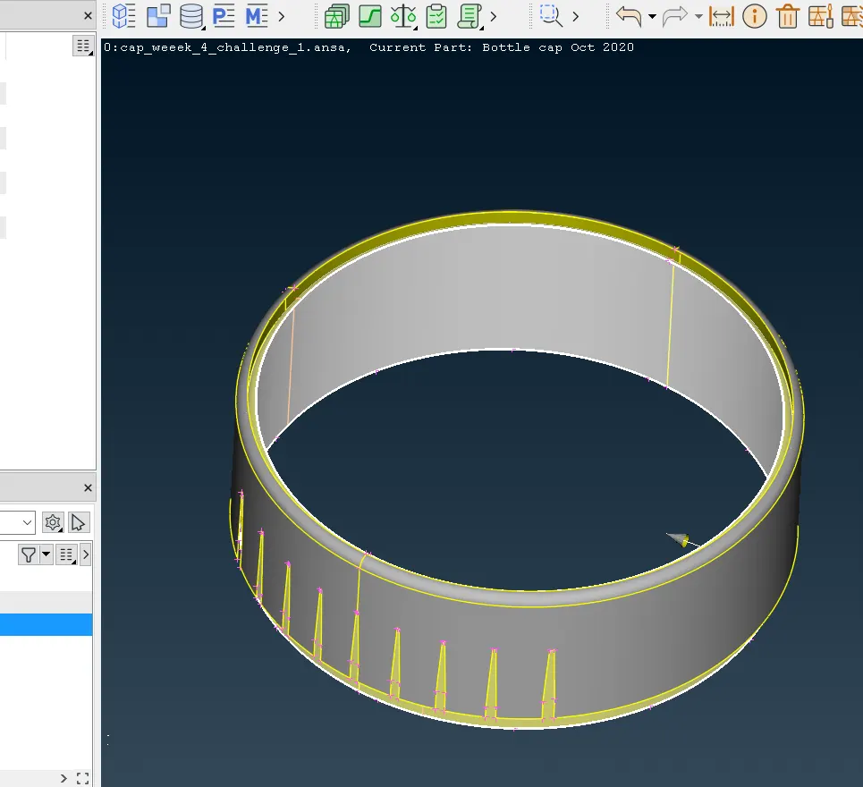
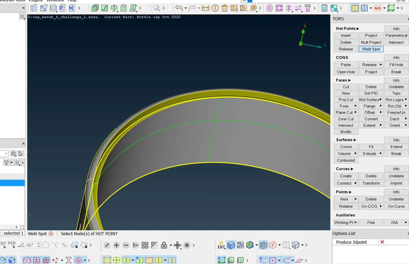
project option(topo-hot points-project-select the point to project-select the target surface-ok) and use the measure option to measure the distance between two weld spots. as shown bellow
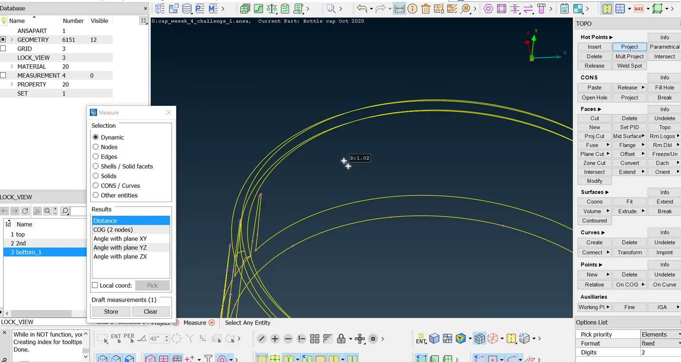
Therefore, the offset option is used to create the surface as shown below
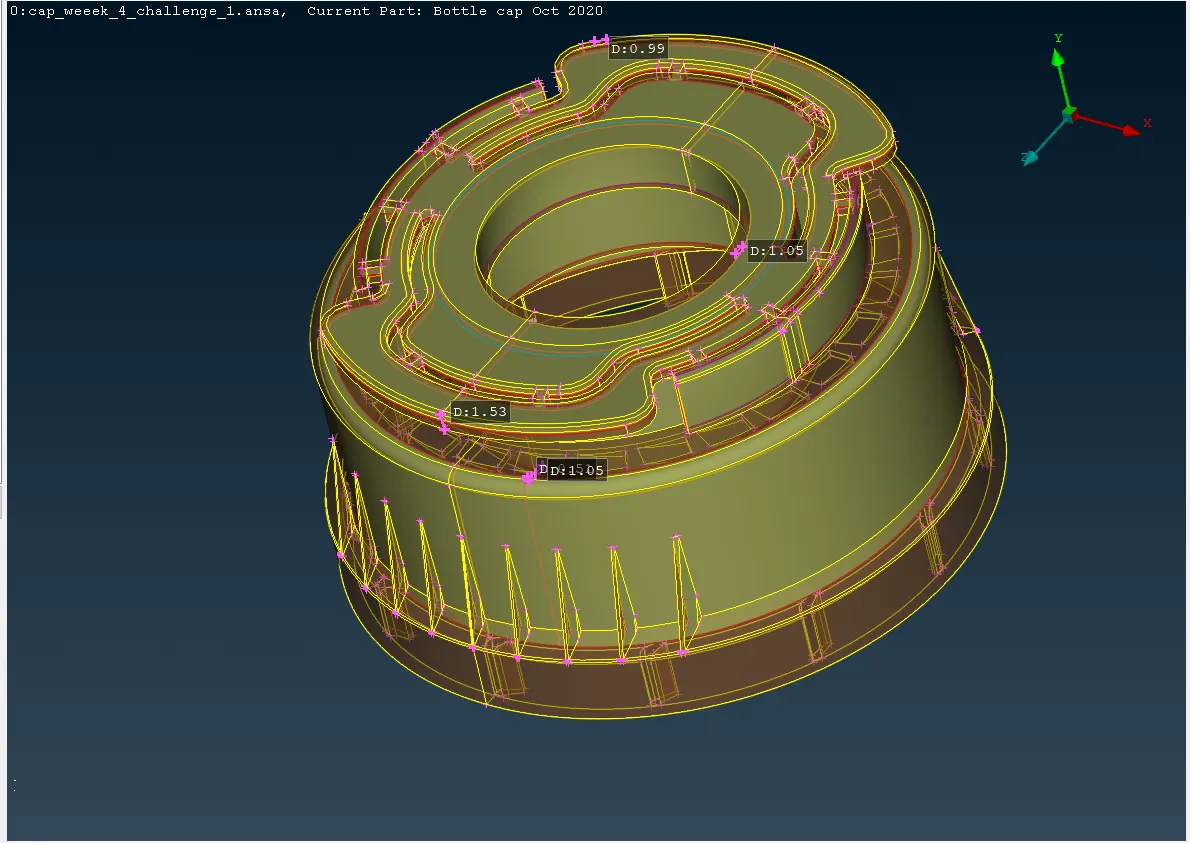
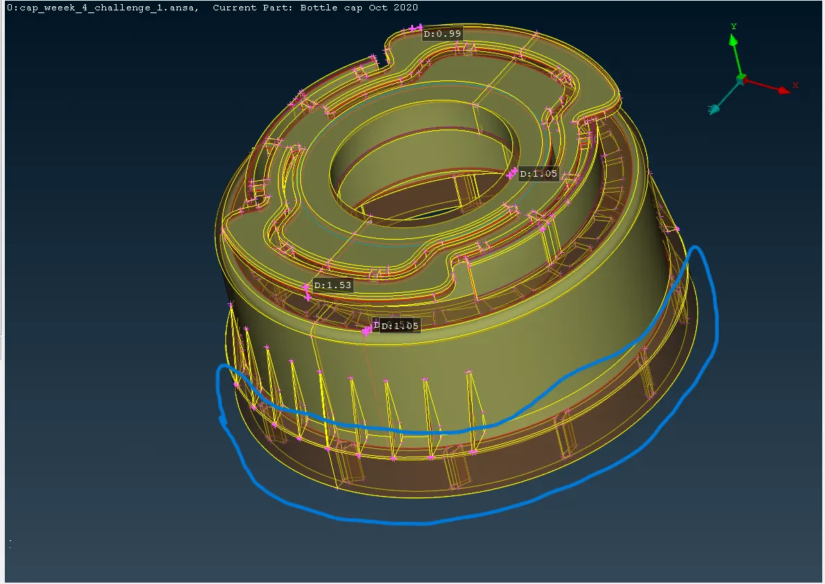
as shown below fig midd surface for bottom feature is created by offcetting the outer surface beacuase inner surface is attached to extrafeatures(ribs) so, its easy to extract midd surface though outer parent surface. the result will be as shown below.
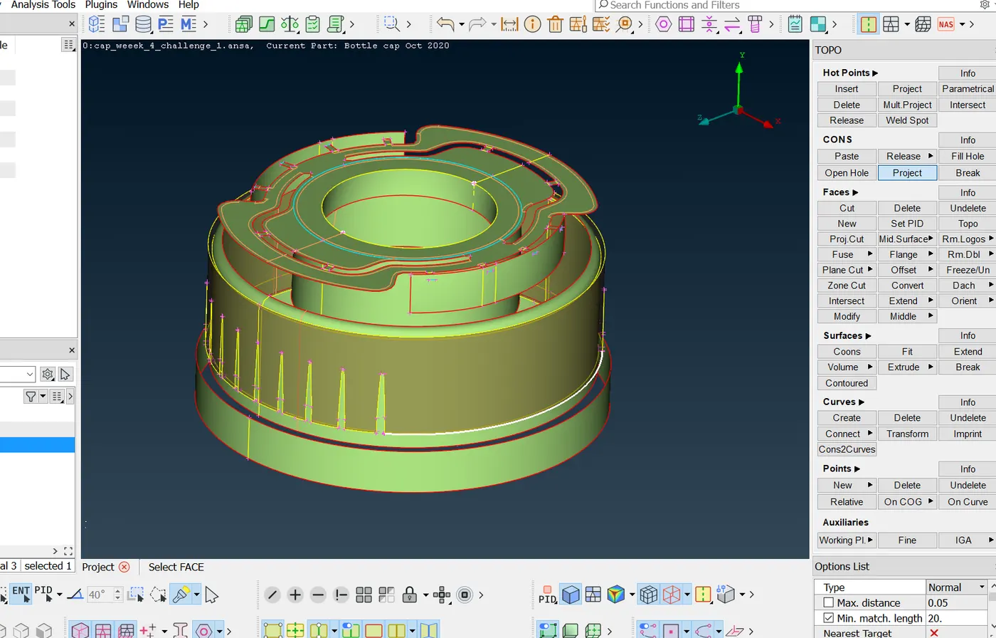
as surface 1 and surface 2 connected in a slanted way we need to delete an extra surface from surface 2 we can identify this extra surface that needs to be deleted is by projecting the parent surface con onto the midd surface (as shown above). after deleting extra surface we can connect surfaces(1 & 2 ) by using (topo-faces-new-cons option) as shown bellow.
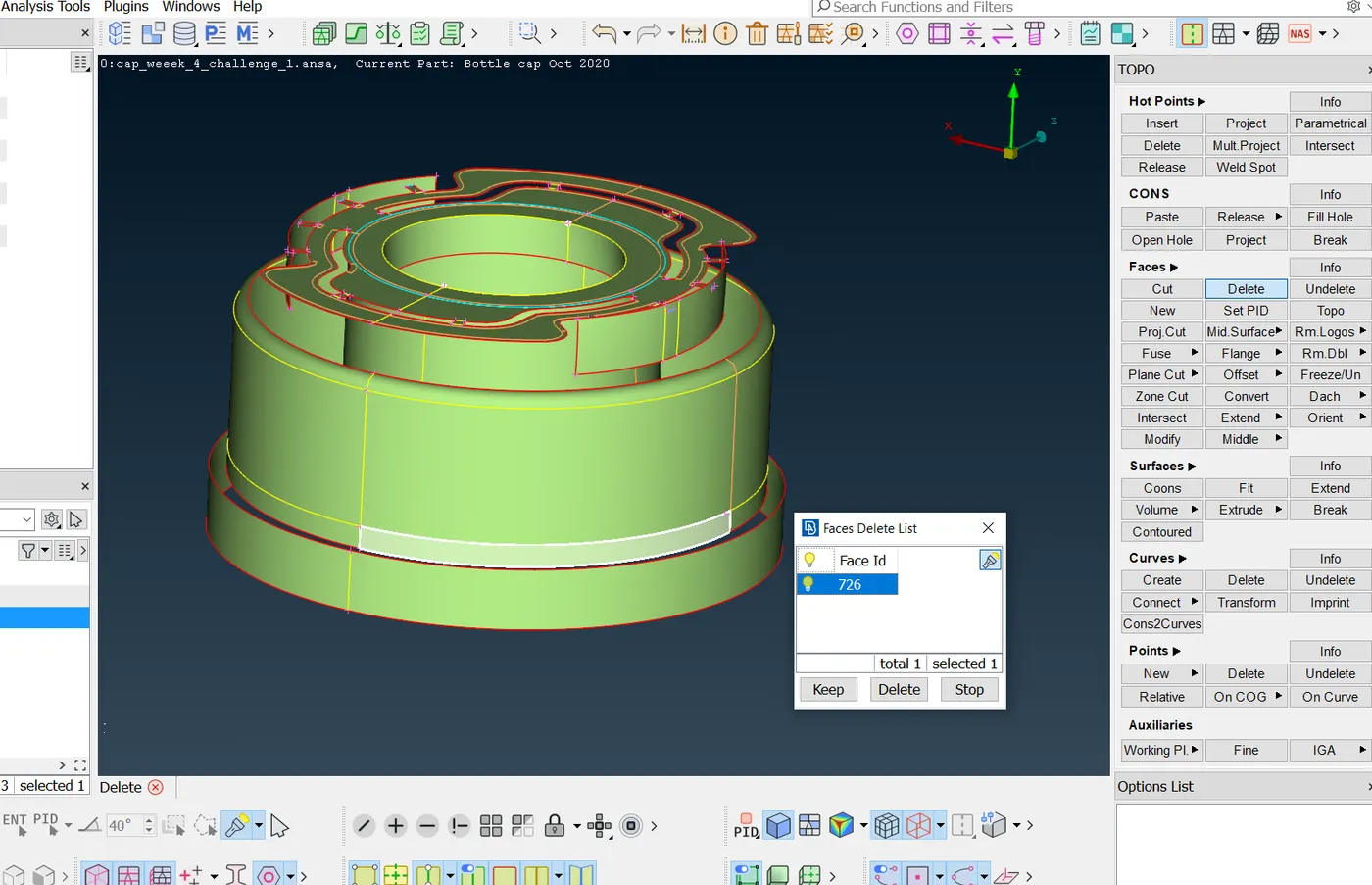
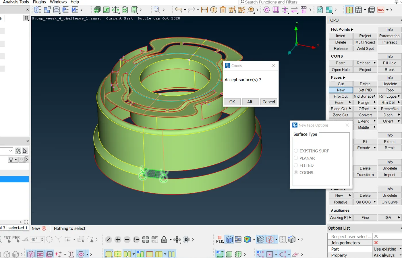
Remaining small features as shown below
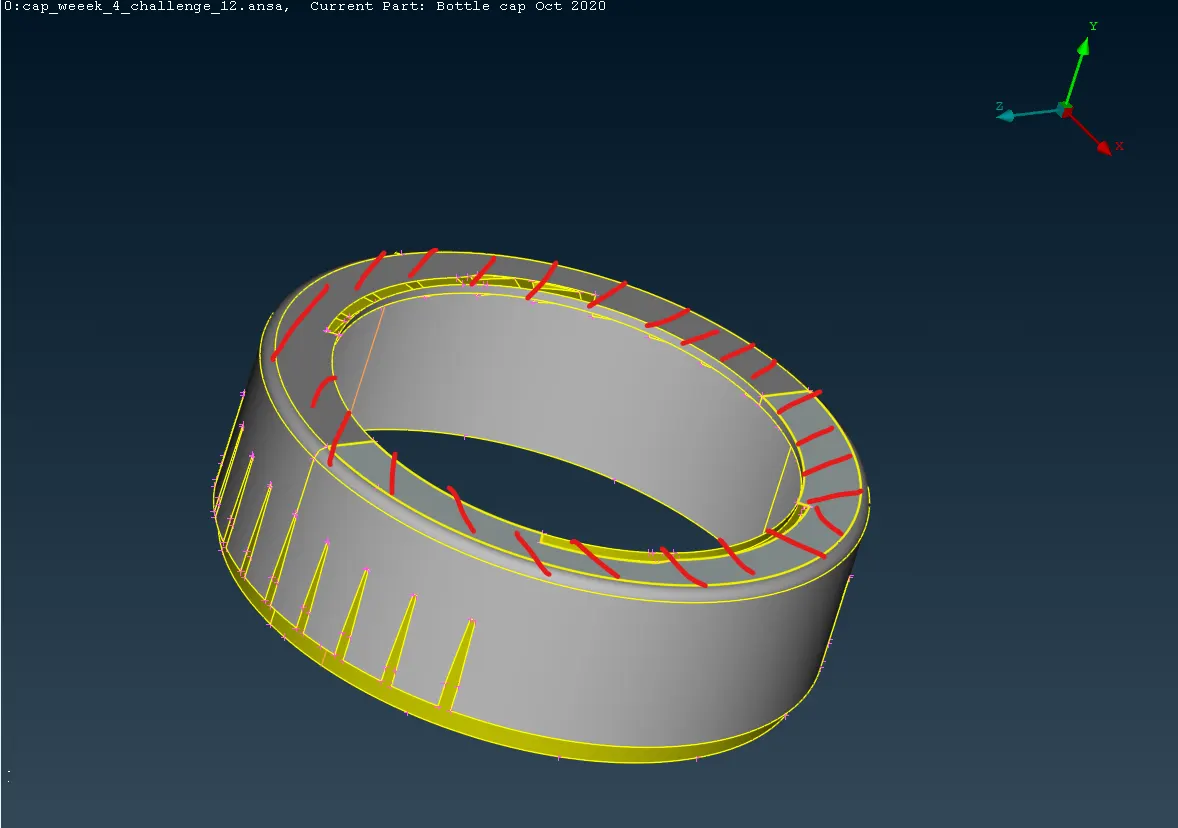
to extract midd surface for the shadded area used the middle curve method where we create the middle curve and a surface between the middle curve and con of midd surface as shown below.
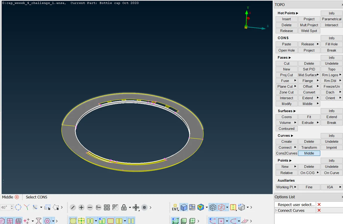
cons are converted to curves for creating surfaces.
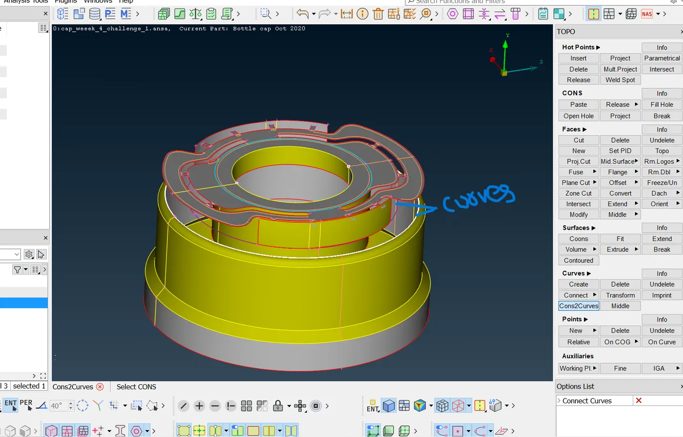
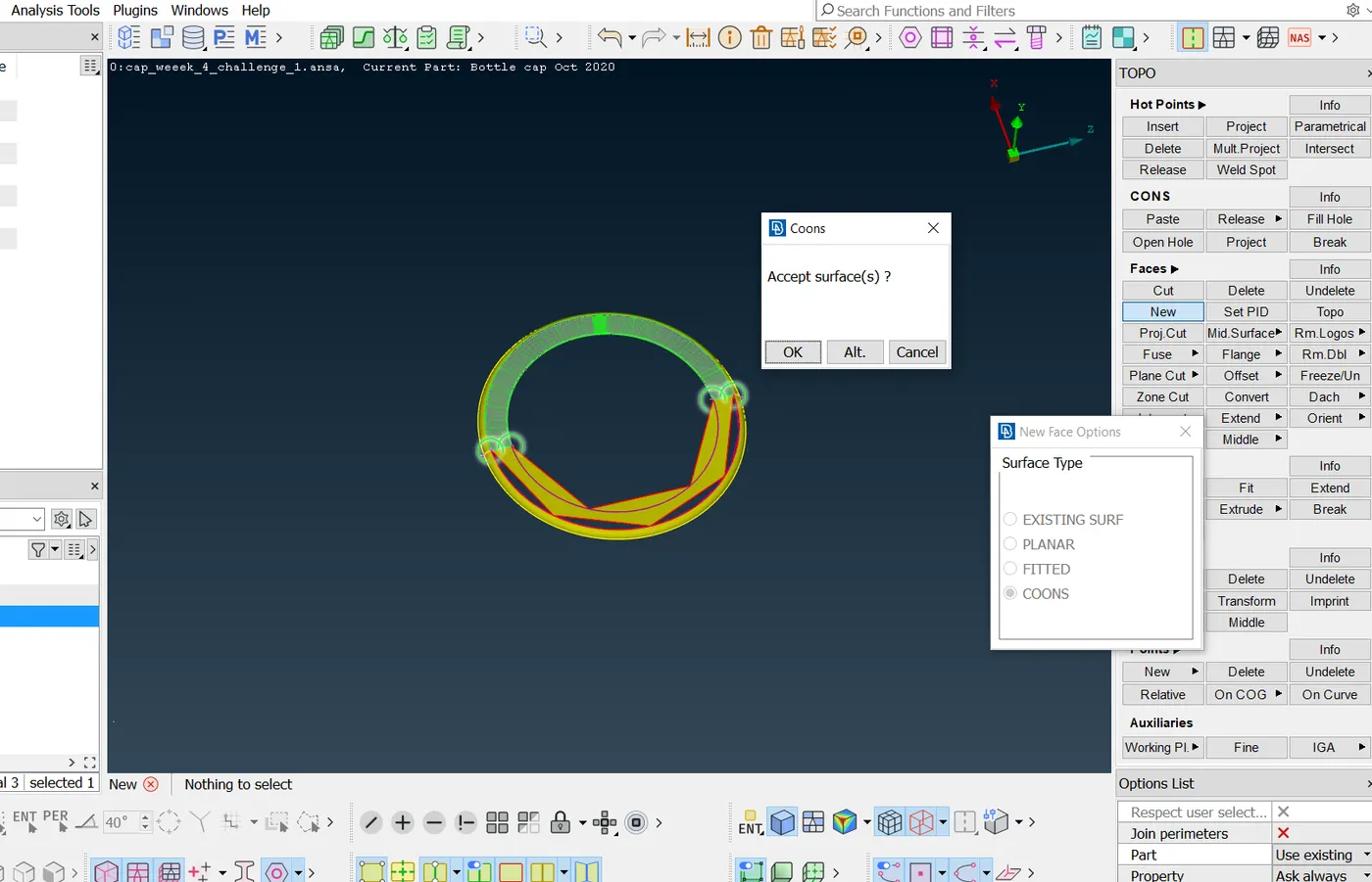
new surface is created between the curves
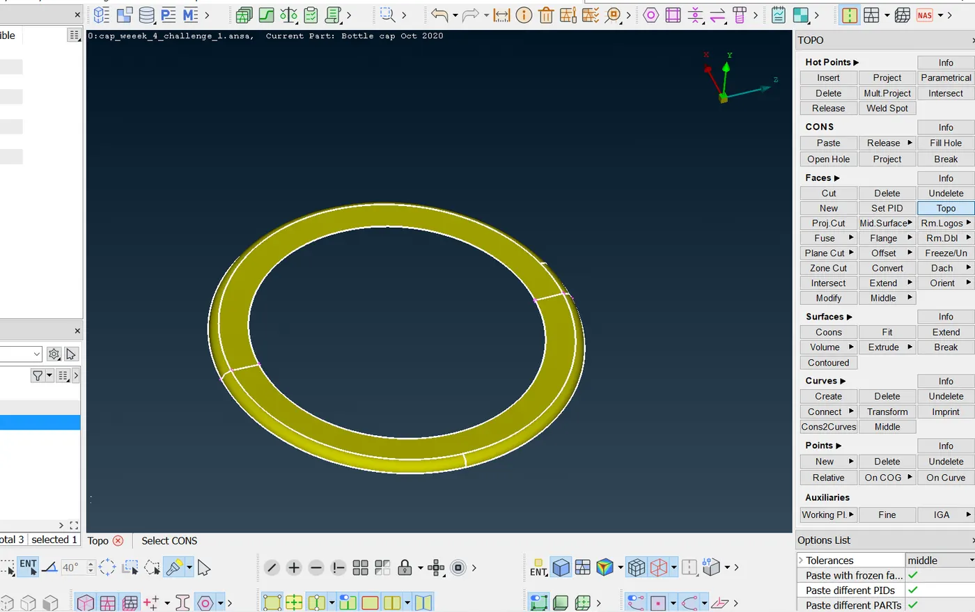
topo is given to connect the surfaces.
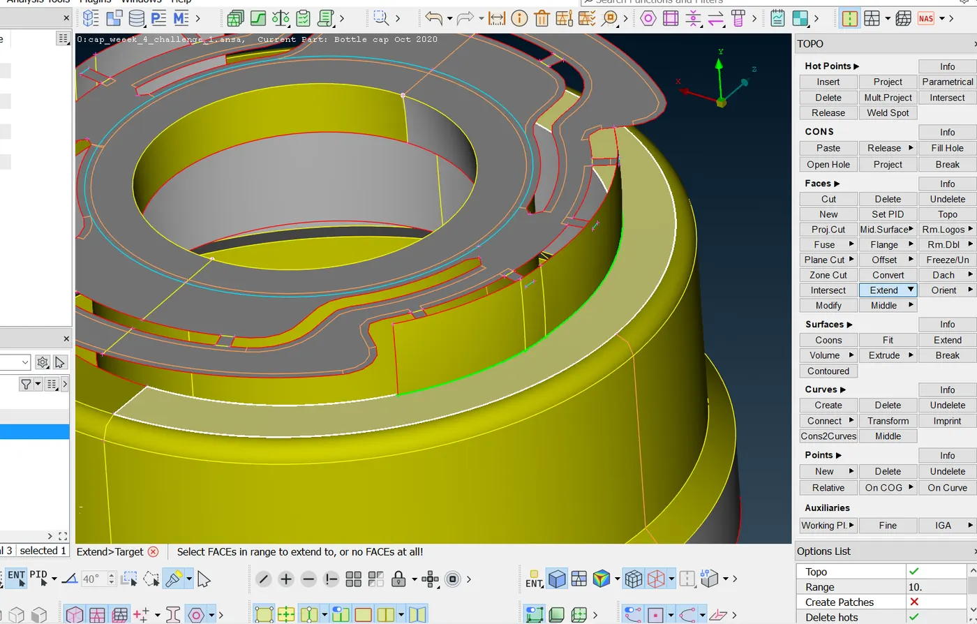
surface that is needed to connect to the above surface is connected by the extend option as shown below. which is shown in green colour.
till now middsurface looks as like below
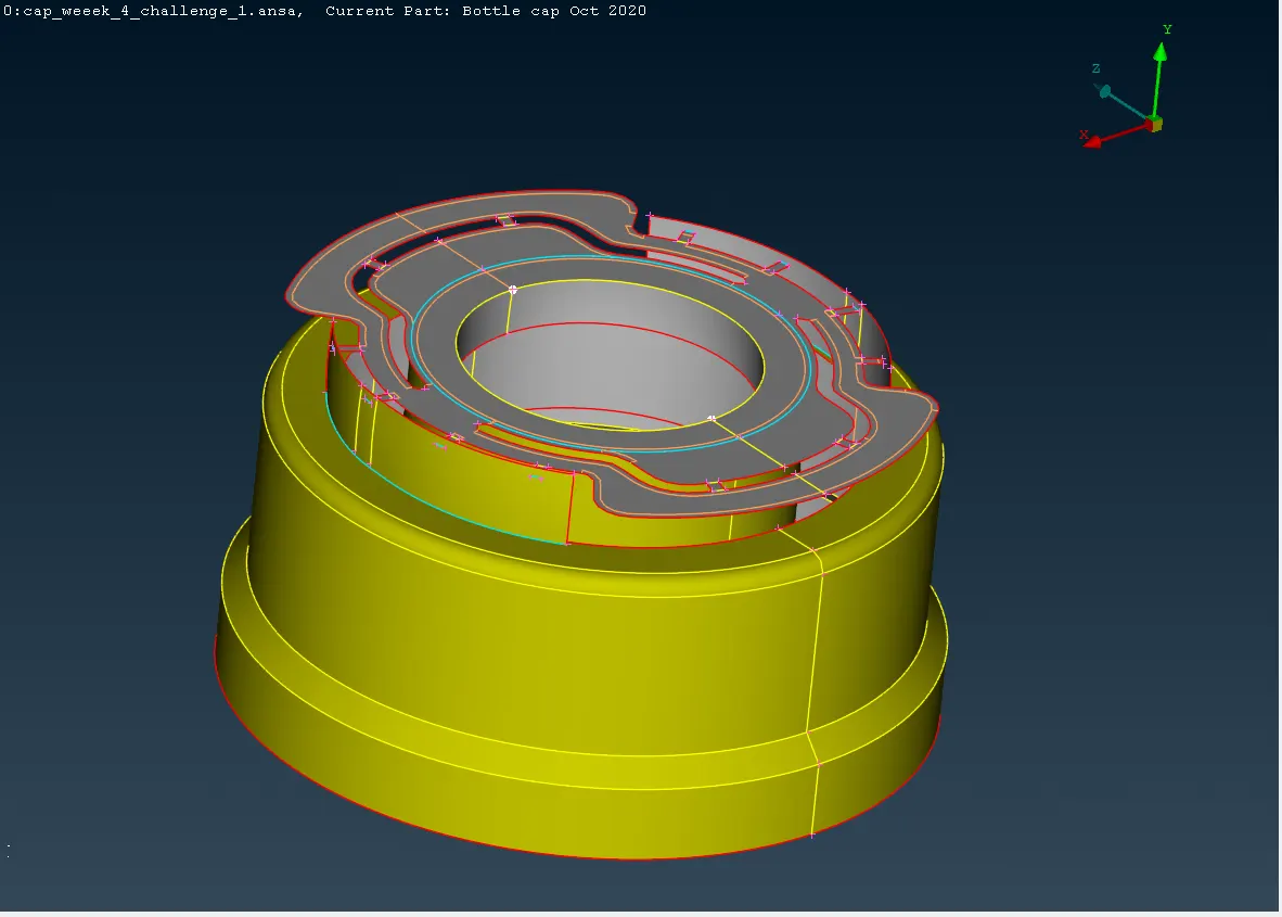
faces middle option is used to create surface and extend option is used to connect surfaces.
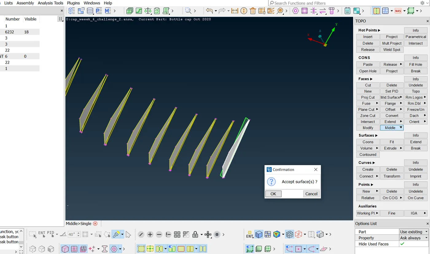
after extending extra unwanted surfaces are trimmed and deleted.
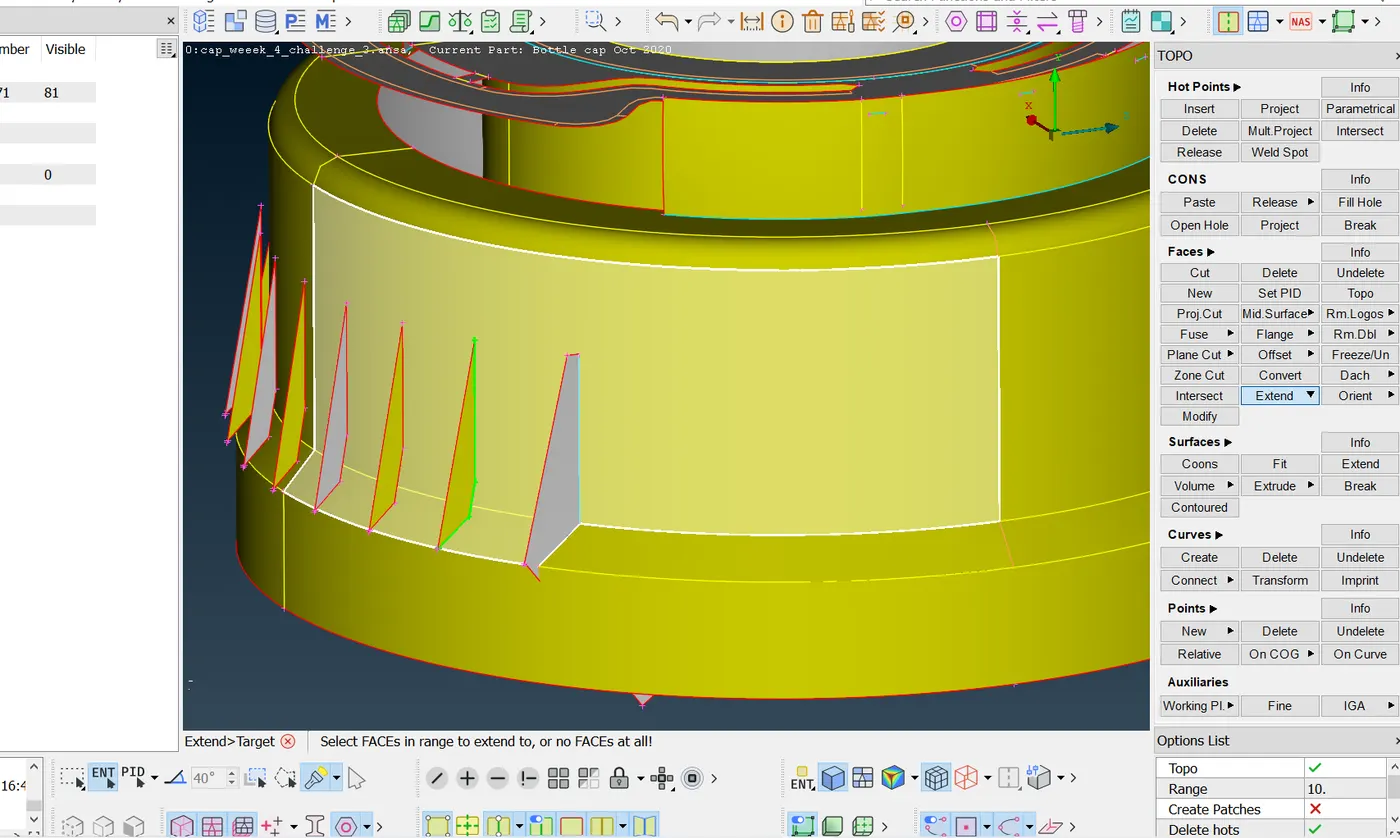
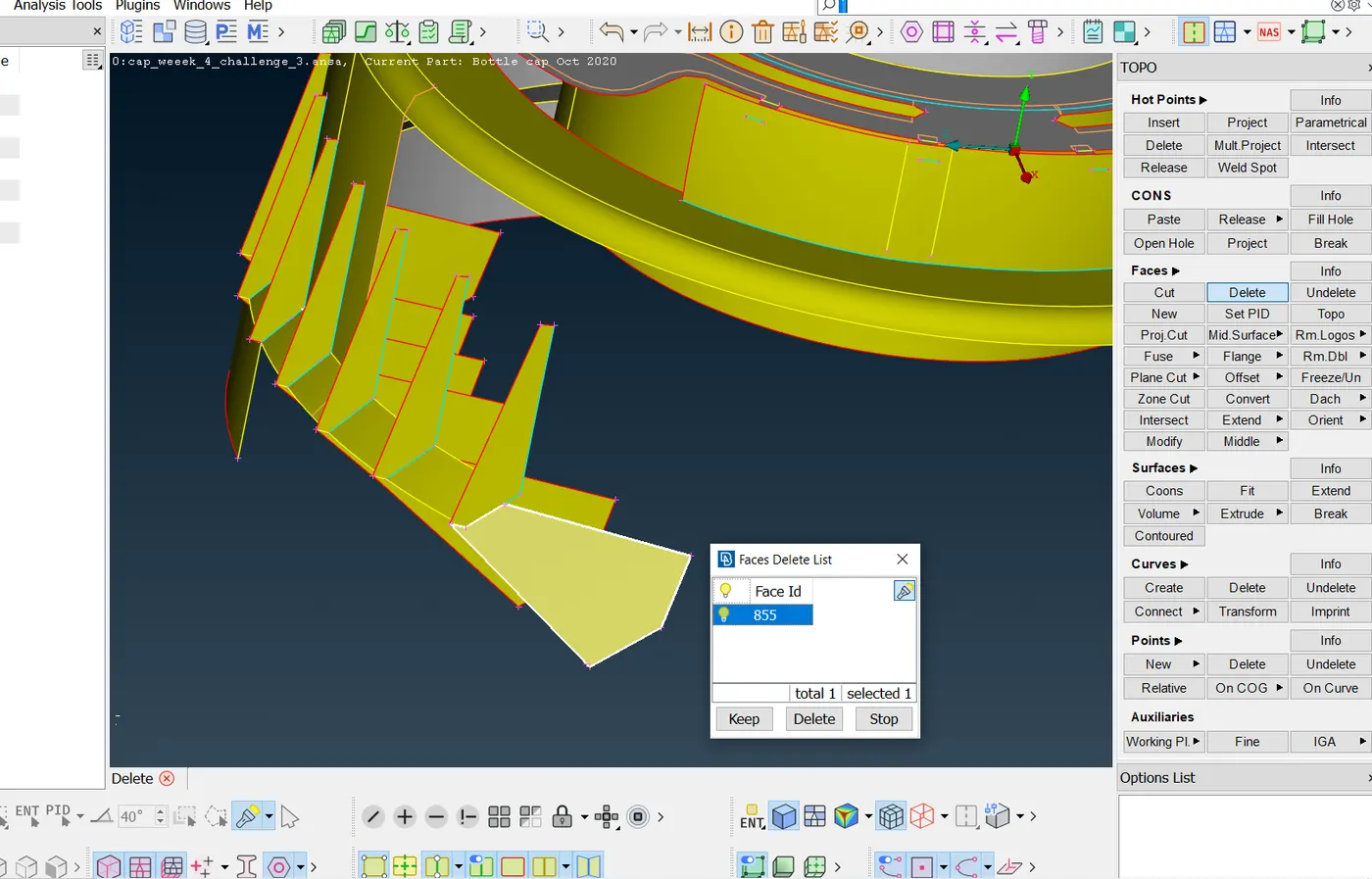
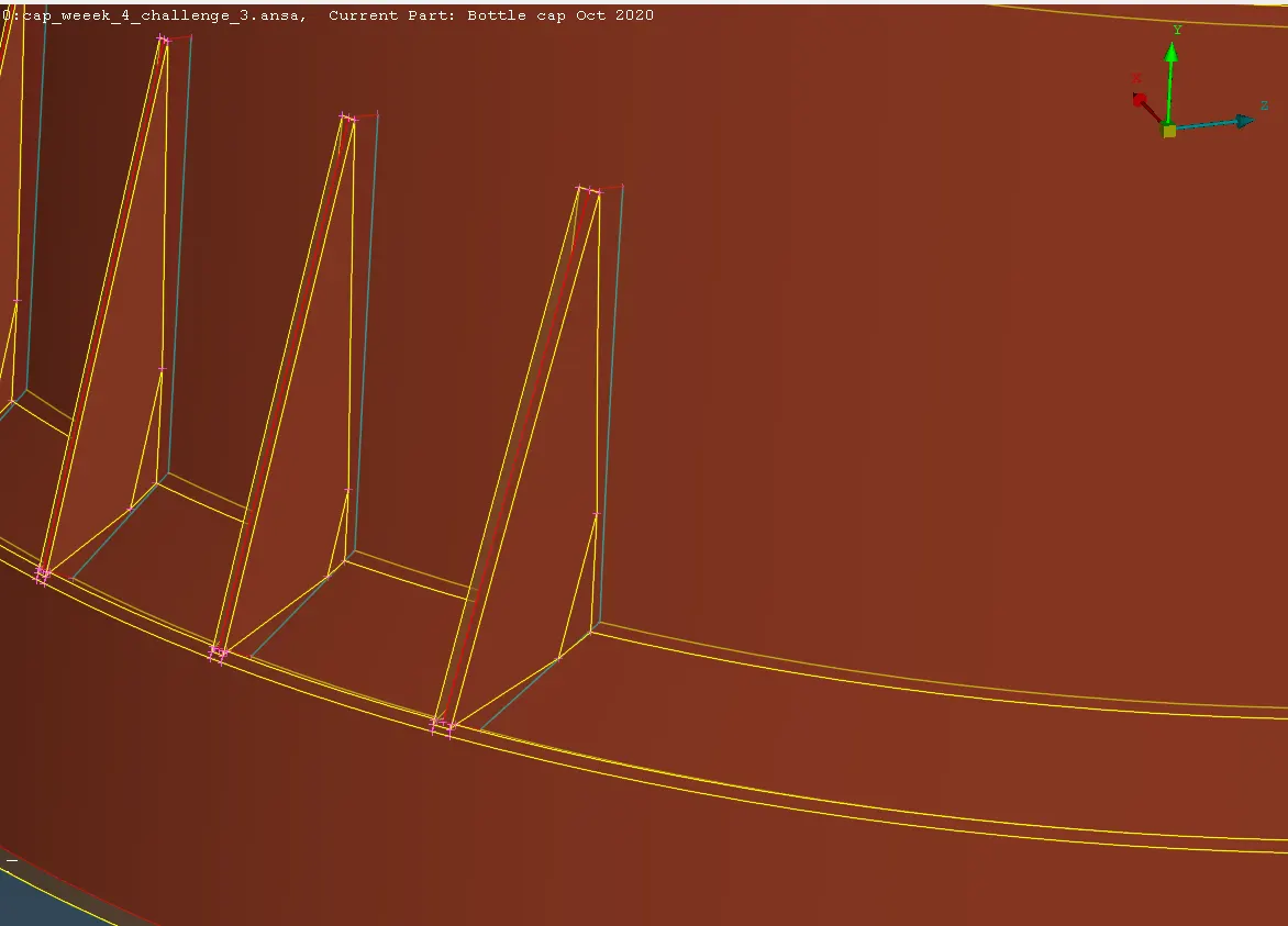
for the below feature faces middle option is used to create surfaces. The topo option is used to connect the surfaces.
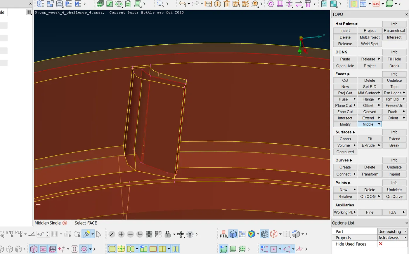
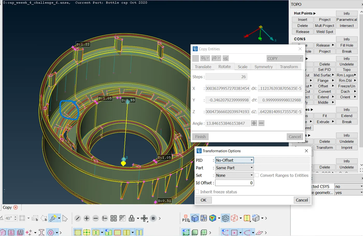
create cog points to create circular pattern
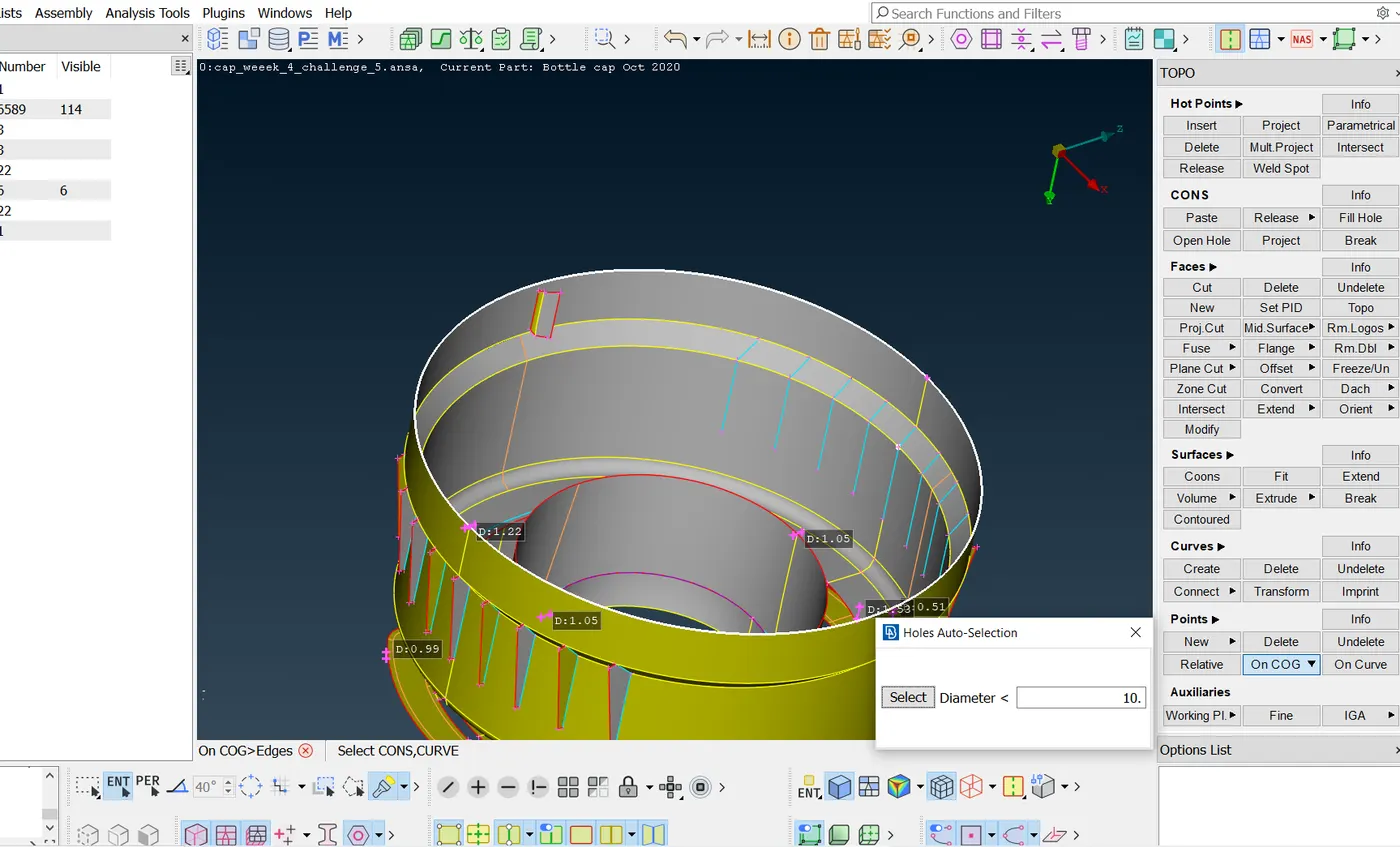
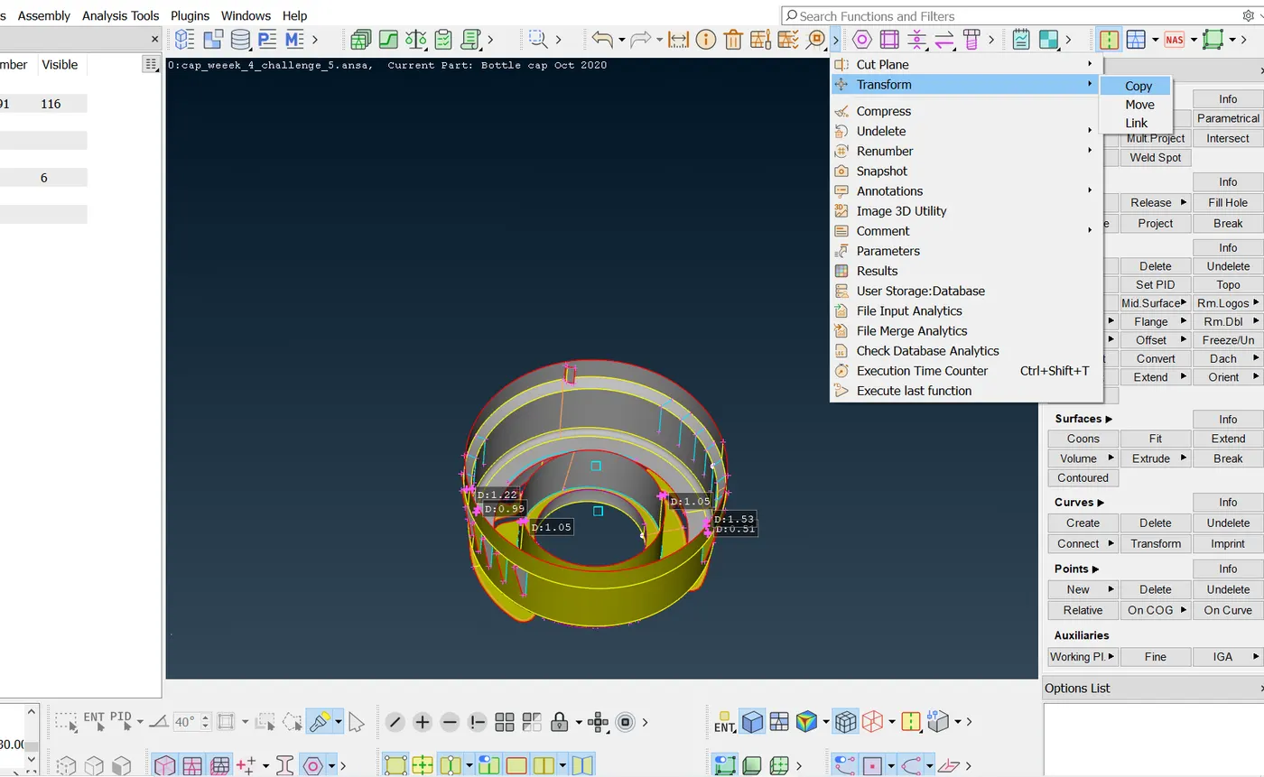
To create a circular pattern of features as shown below select transform-copy-select entity-select Rotate-select direction of axis- no of steps (here 12)-angle(30)-ok then transformation option will popup-keep default option-ok.
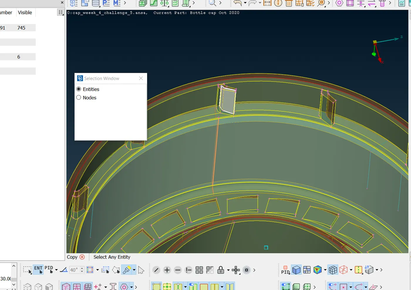
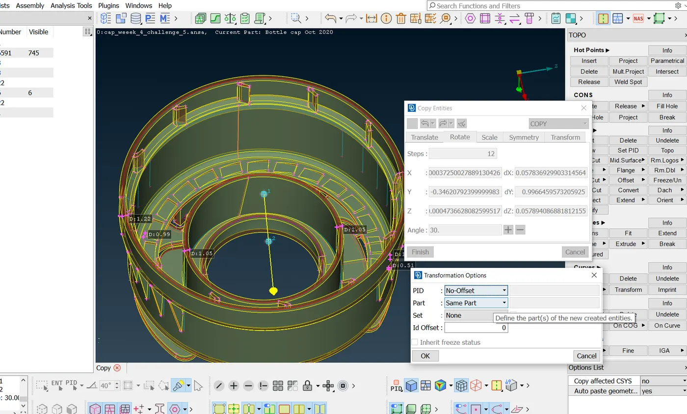
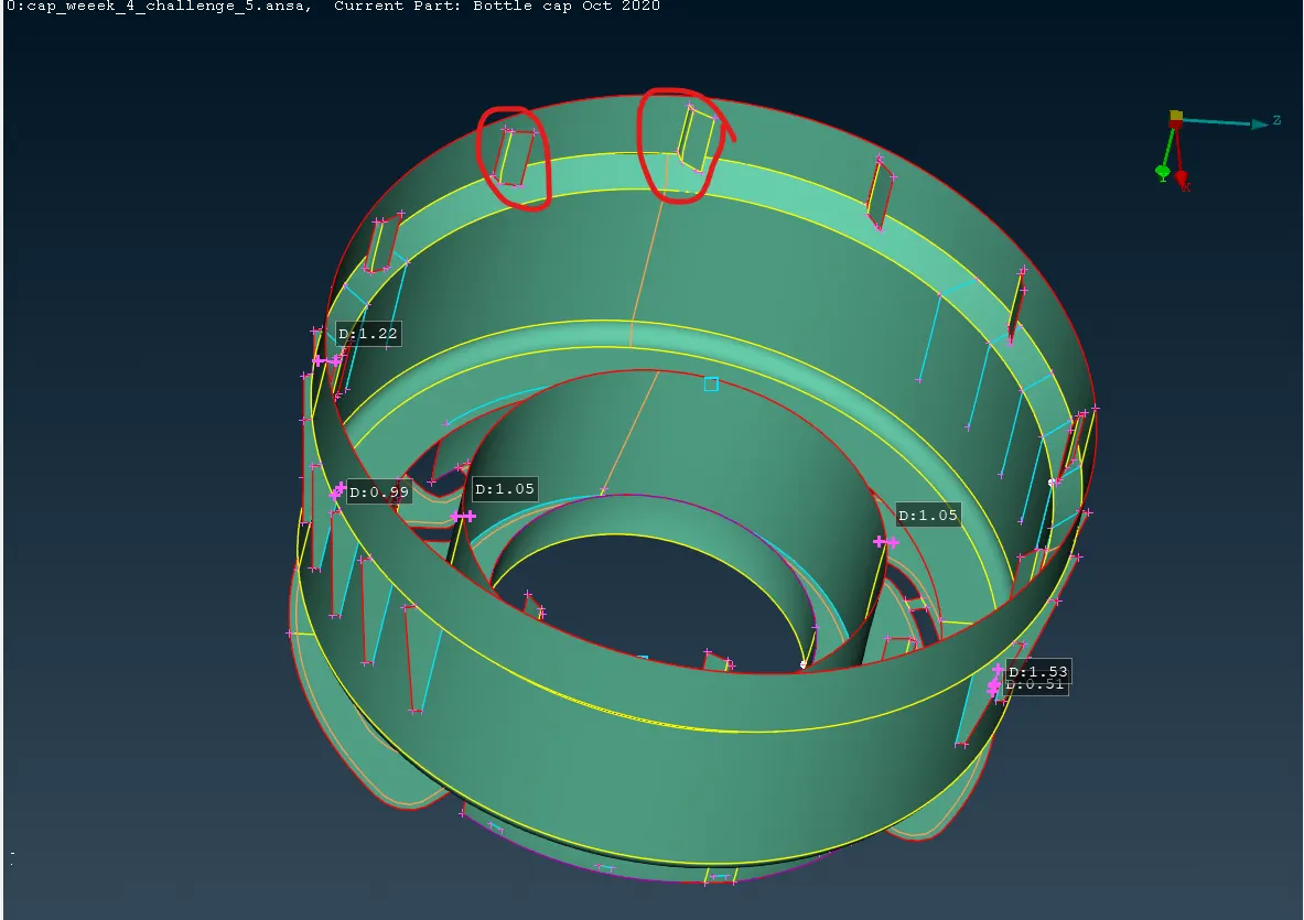
extend option is used to connect with base surface and extra unwanted surfaces are trimed and deleted.
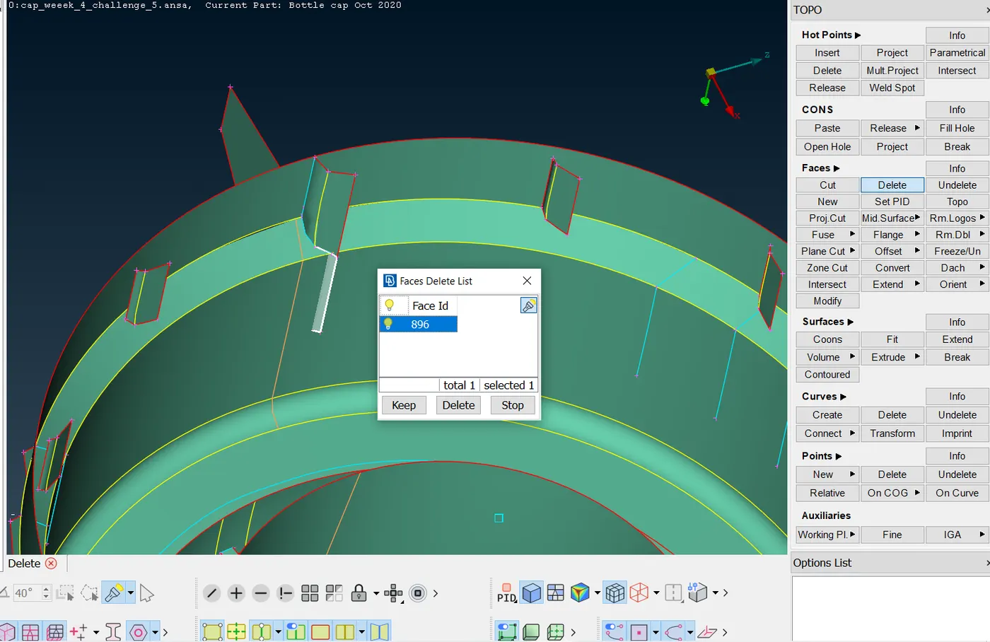
The features shown below are also modelled as above.
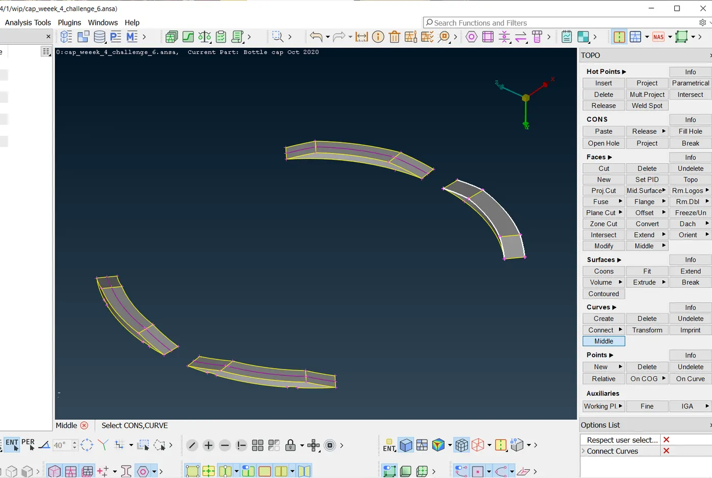
features middle curve option used to extract middle line through that surface created by using surface- extrude option and then by faces-extend option surface is connected with the base surface.
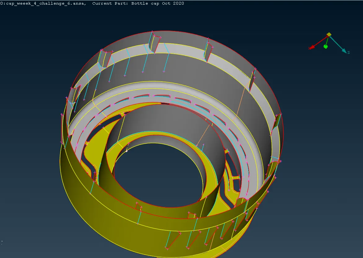
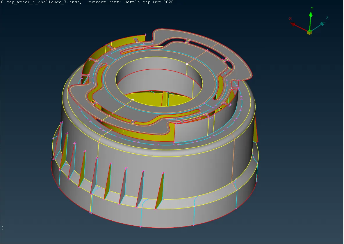
Unwanted lines are trimmed using the face cut option and the final middle surface for the bottle cap is shown bellow.
2.MESHING
setting parameter and mesh criteria
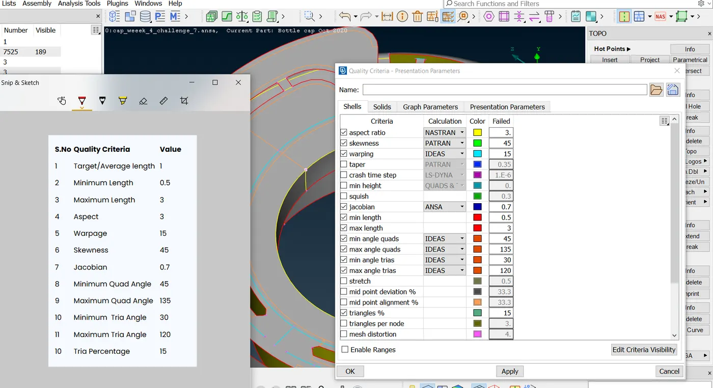
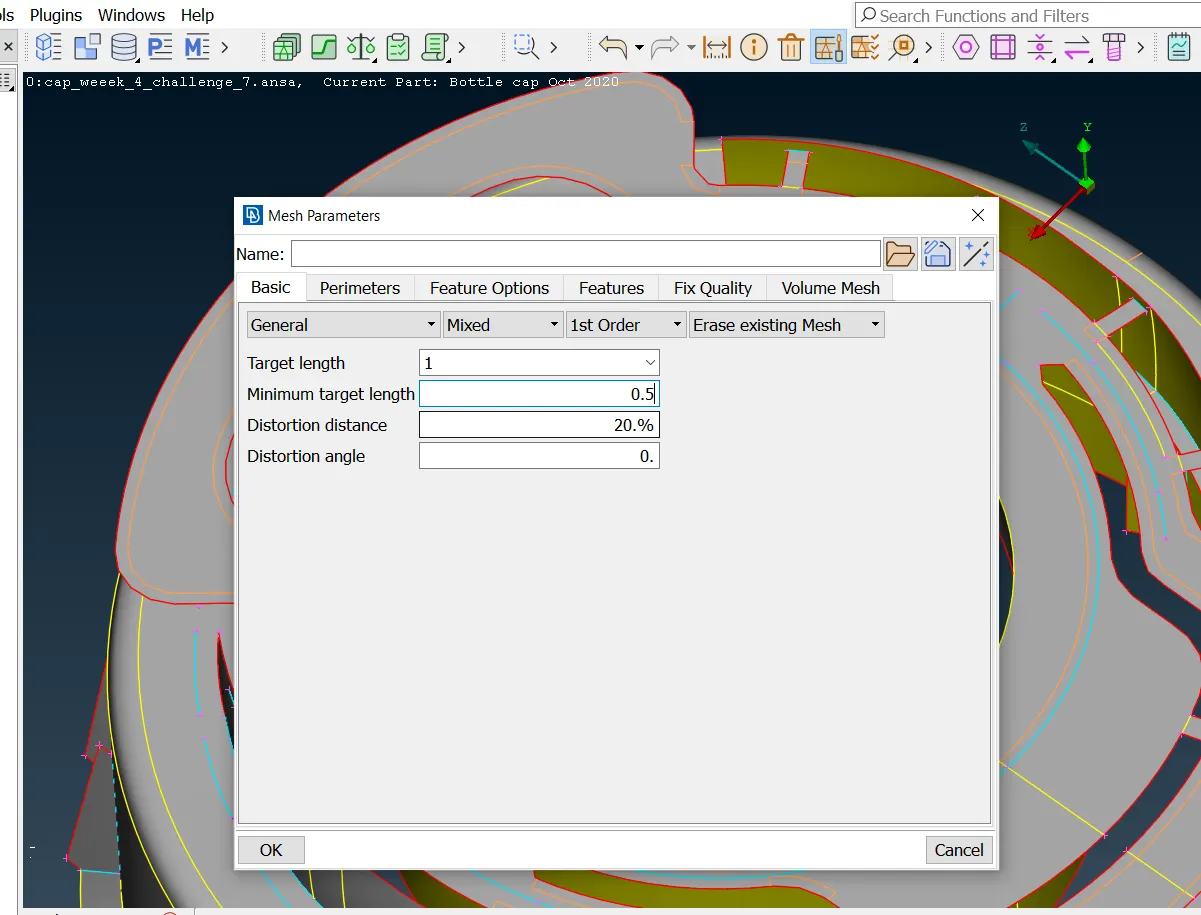
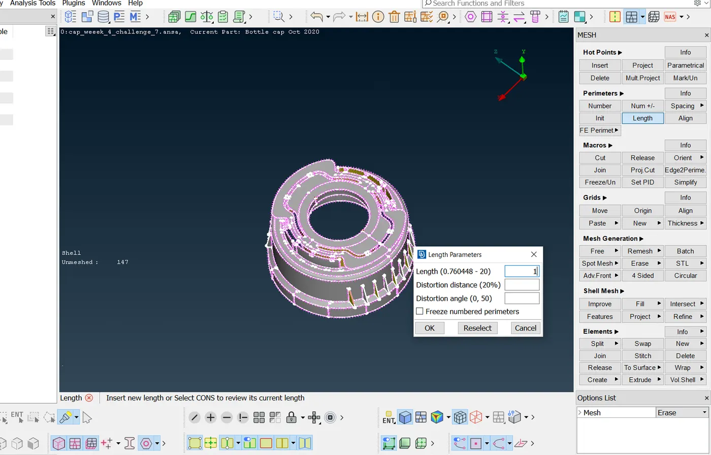
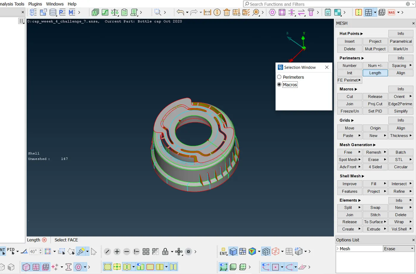
set perimeter length to target element length(mesh-perimeters-length-select-perimeter (macro)-select surfaces-ok)
here i am using best mesh option to generate mesh in this select best mesh option (classic mesh module-mesh genaration-best mesh-select surface to mesh -give ok)
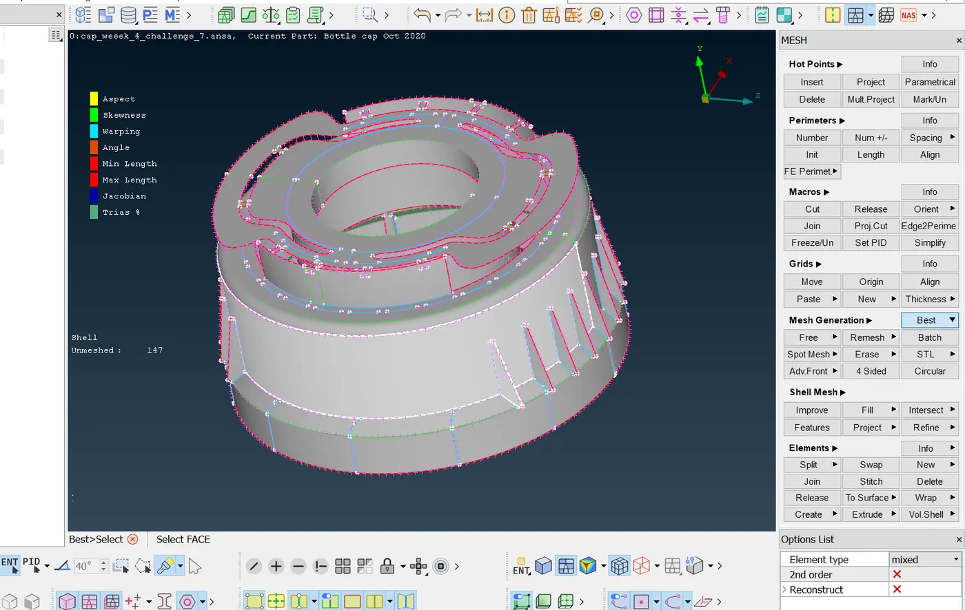
if any unmeshed surface is left we can identify from bellow option.
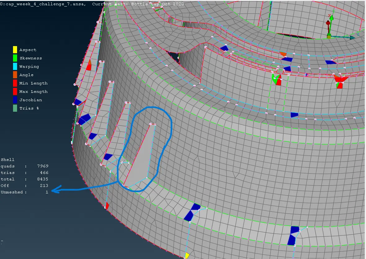
as shown above, there are too many quality failures and improper mesh flow. therefore we can clear it by adjusting nodes and elements and creating and suppressing cons.
By increasing the numbering(mesh-perimeters-num+/--right click to increase numbering left click to decrease numbering on the con) of nodes, we can see how we can improve mesh flow and avoid trias on fillet areas. (this will increase the number of nodes and the number of elements).
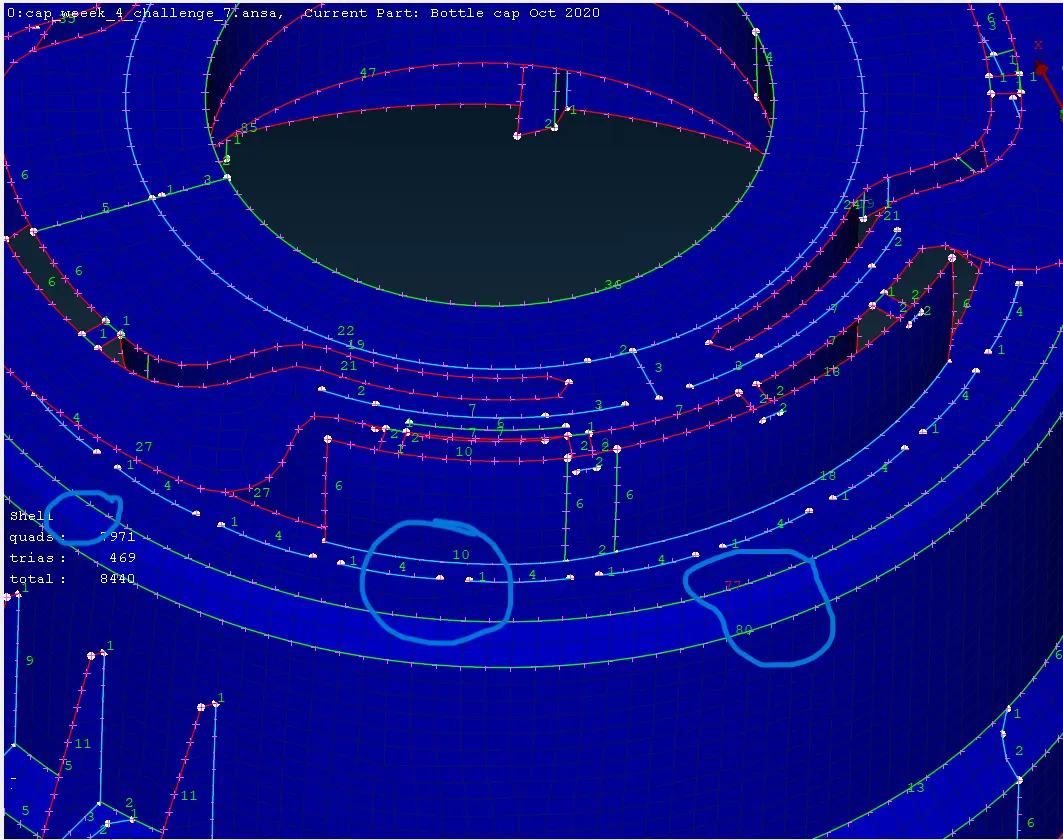
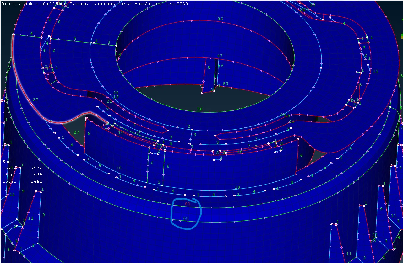
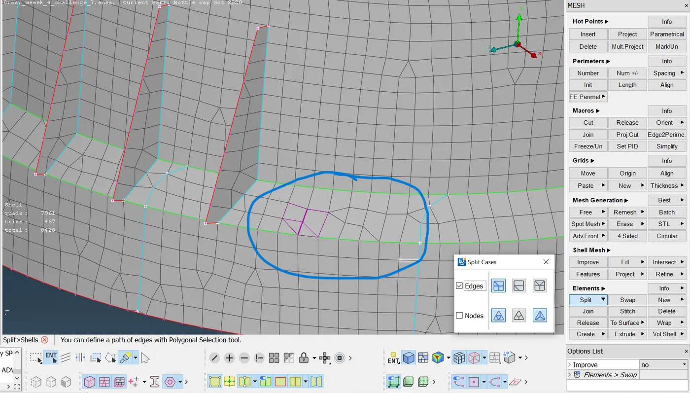
Opposite trias can be eliminated by using split command (MESH-ELEMENTS-split-select edge option-right click the edge to split-ok to conform split) as shown bellow.
3.QUALITY checks
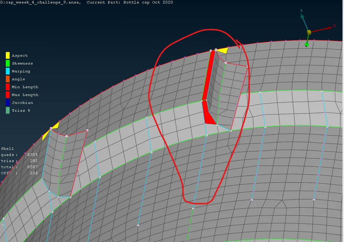
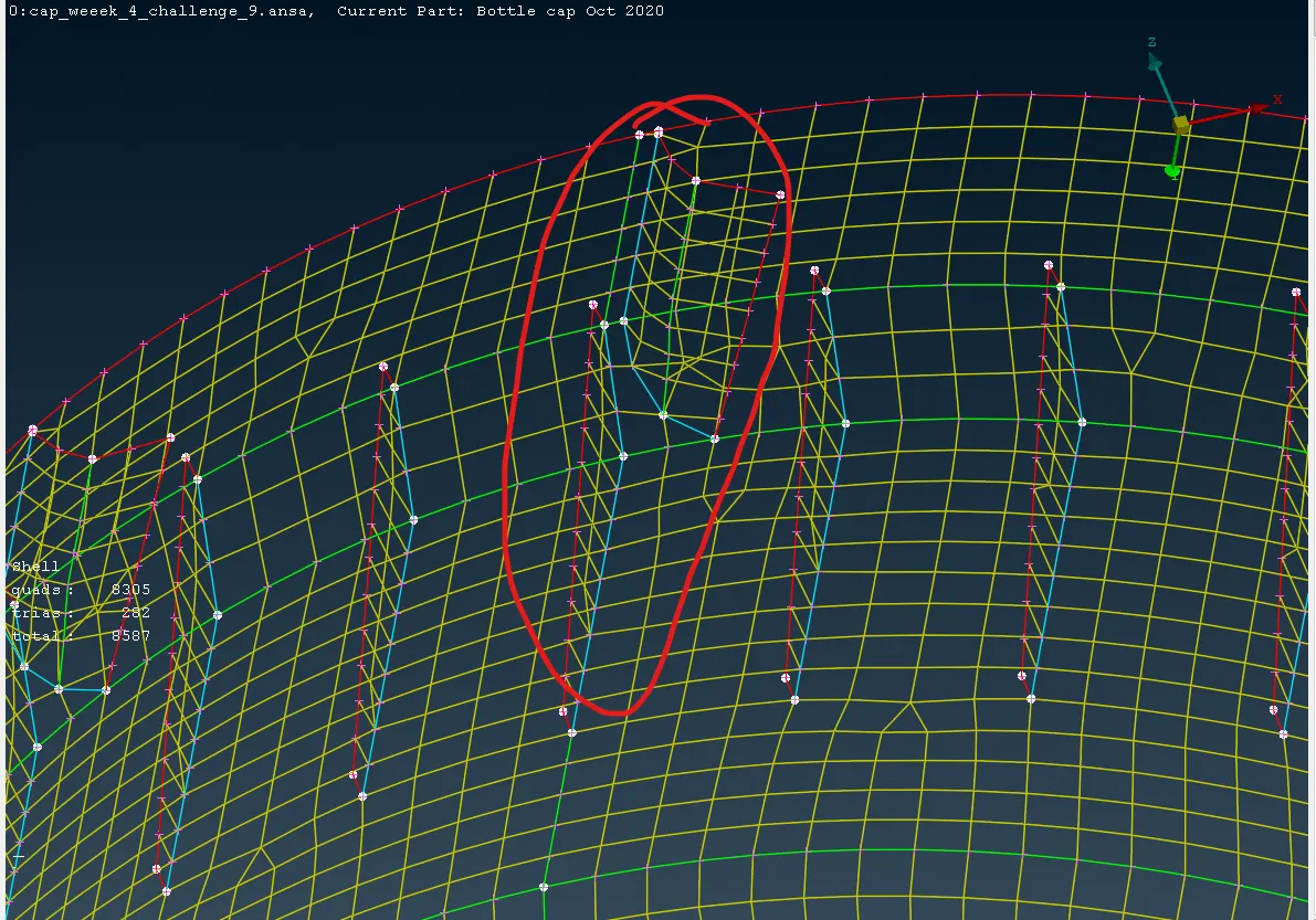
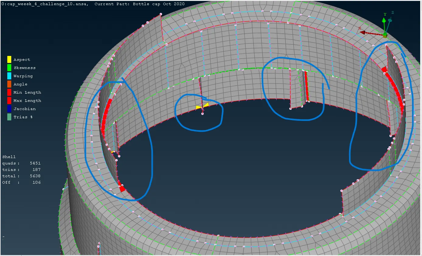
most of the quality failed elements can be corrected while adjusting mesh flow.but some areas as shown below elements intentionally let them failed becuase of feature contrains as shown bellow.
4. thickness assigning
measure the thickness of every feature by using the mesure command like as bellow
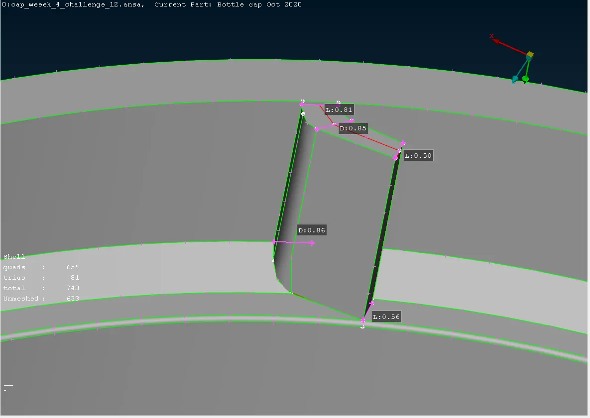
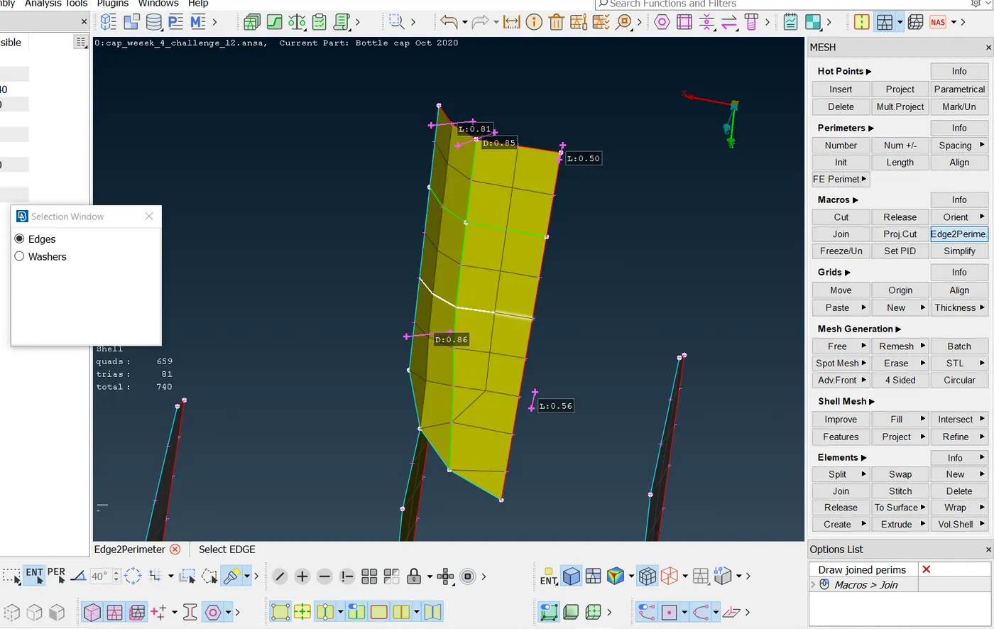
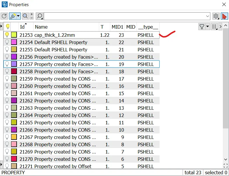
based on a variation of thickness from upper range to lower assign the thickness to elements in increasing or decreasing intervals of thickness.to assign individual thicknesses to elements we need to create individual properties for every thickness variation we assign to an element to suppurate the elements in thickness we use the Edge2perimeter(mesh-Macros-edge2perimeter-select-edge of the element to cut-ok(edge created in green colure)) option.
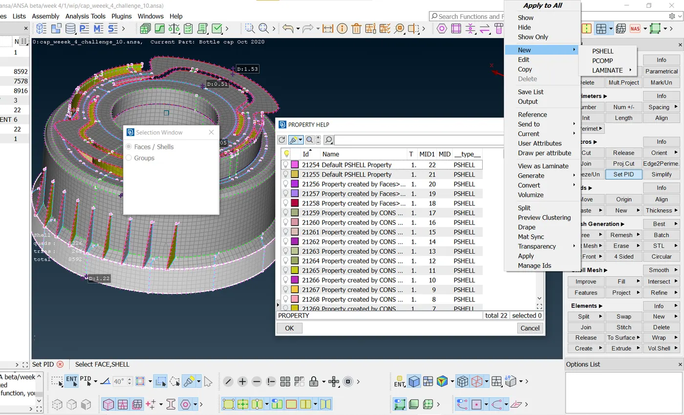
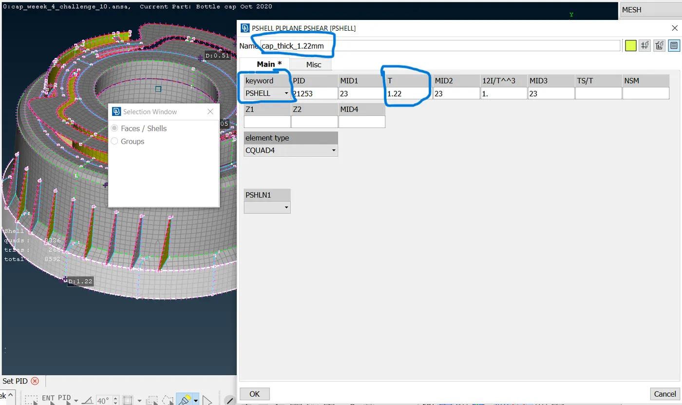
to create a property or to assighn thickness, we use setpid(Mesh-Macros-set PID-select faces of elements to assign thickness-middle click(ok)-property tab will popup-give right click on the tab-select NEW-PSHELL-then give name-thickness value-check element type once-ok)option as flows.
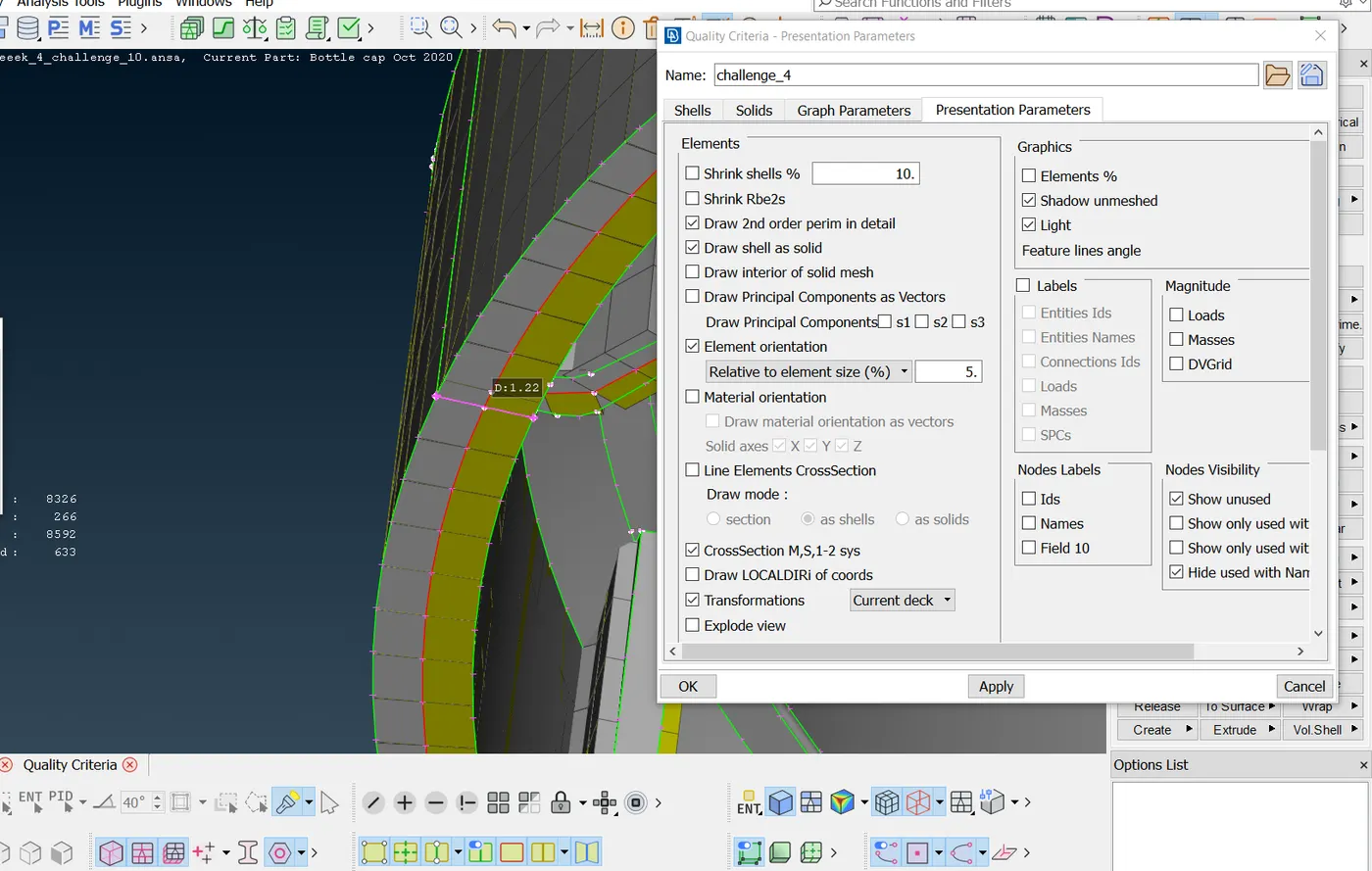
to check whether thickness was assigned properly matching to cad. in the quality criteria tab-presentation parameters -turn on Draw shell as solid.
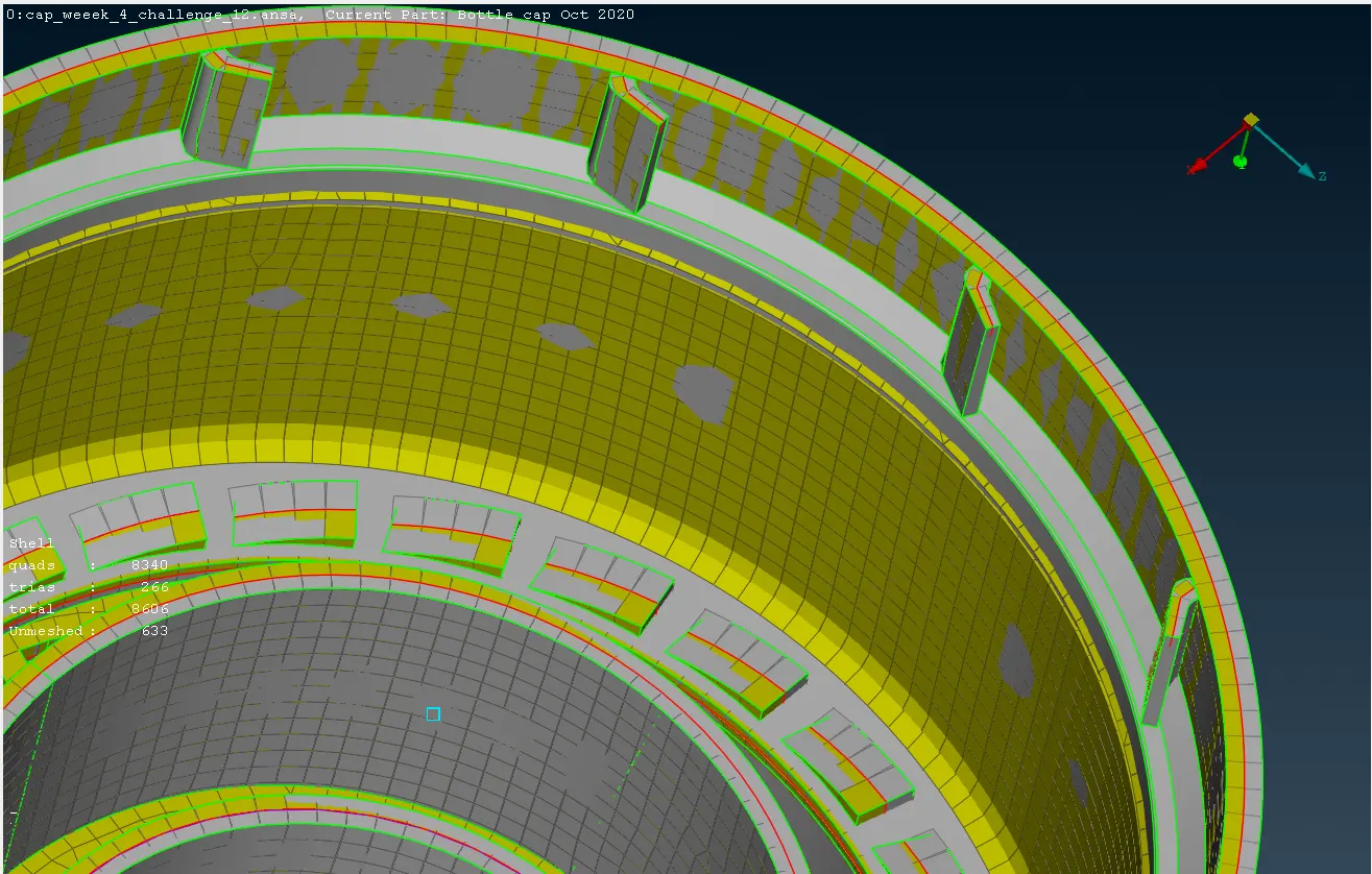
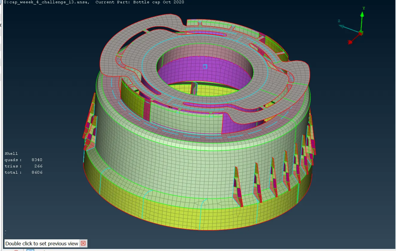
final model:
note:
1. The teeth profile is not there in the parent CAD I received.
2. as the cad file size is larger, parent and mid surface files shared separately.