Week - 4 - 2D meshing for Plastic components
Objective: To verify that there are no geometrical mistakes and to do midsurfacing using the proper midsurfacing procedures for the model that was given. Assign PID and thickness to each of the midsurfaces, and ensure that the mesh meets the quality standards for the elements that have been provided.
ANSA:
The automotive industry makes extensive use of the computer-aided engineering tool known as ANSA for finite element analysis and computational fluid dynamics (CFD) analysis. BETA CAE Systems is the company that created it. A number of BETA CAE Systems subsidiaries and business agents work together to disseminate the software all over the world.
ANSA ensures that the connection between the CAD geometry and the FE mesh remains intact. This indicates that the FE meshes are superior representations of the geometric parents to which they belong. Additionally, it is simple to maintain and update any changes in the geometry by merely rewriting the updated region rather than starting from scratch to recreate the FE. This makes it straightforward to do so.
It includes many unique algorithms for meshing that are appropriate for computational fluid dynamics (CFD) simulations as well as structural models. Automatic net generation for structural analysis was the original meaning of the acronym ANSA, but the software has rapidly expanded beyond that scope. TOPO MESH, VMESH, DECK-SOLVER, MORPH, and HBLOCK are the names of the many operations that can be accomplished with the help of ANSA's broadly six menus.
ANSA contains a variety of modules of the following types:
TOPO is an abbreviation that stands for "Set of Tools for Optimizing and Polishing Geometry."
Tools that may create Surface Mesh or 2D Mesh are referred to as MESH.
VOLUME MESH is used to generate a solid or three-dimensional mesh.
SOLVER DECKS are tools that are constructed on the back of several solvers, such as ABAQUS, RADIOSS, and ANSYS, amongst others.
MORPH is an advanced tool that allows for more precise capturing of geometry during the meshing process.
Procedure:
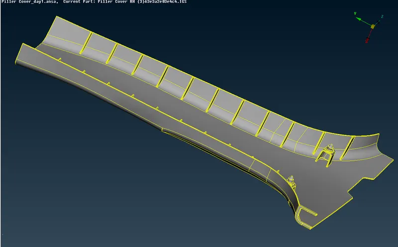
- The initial step is bringing the specified geometry model into the ANSA window and examining it to determine whether or not it contains any flaws in its geometry.
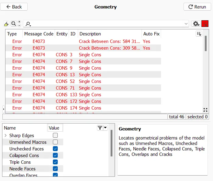
- The check geometry option generates a list of the geometrical and topological faults, such as needle faces, unchecked faces, collapsed cons, and so on, so that these issues can be addressed and resolved.
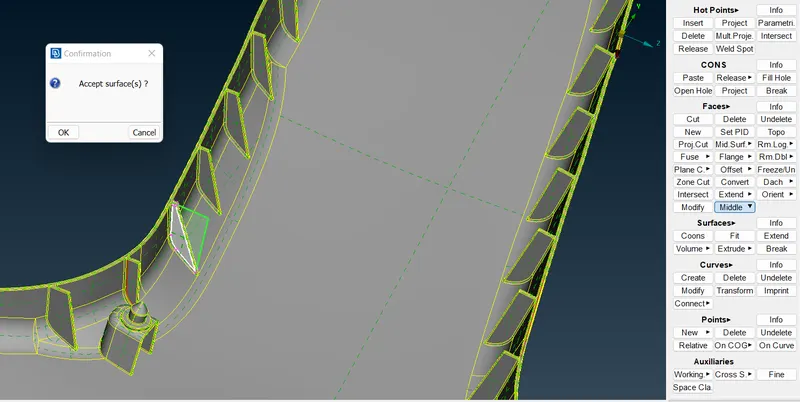
- Fixing the other geometric faults, which typically consist of things like excess hotpoints, surfaces that aren't long enough, parts of the surface that don't need to be cut, etc., requires the use of the appropriate procedure.
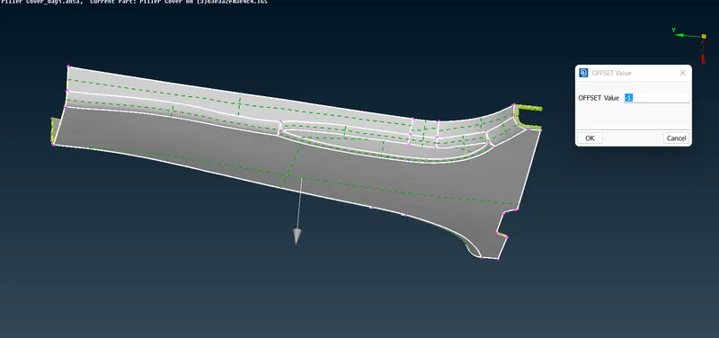
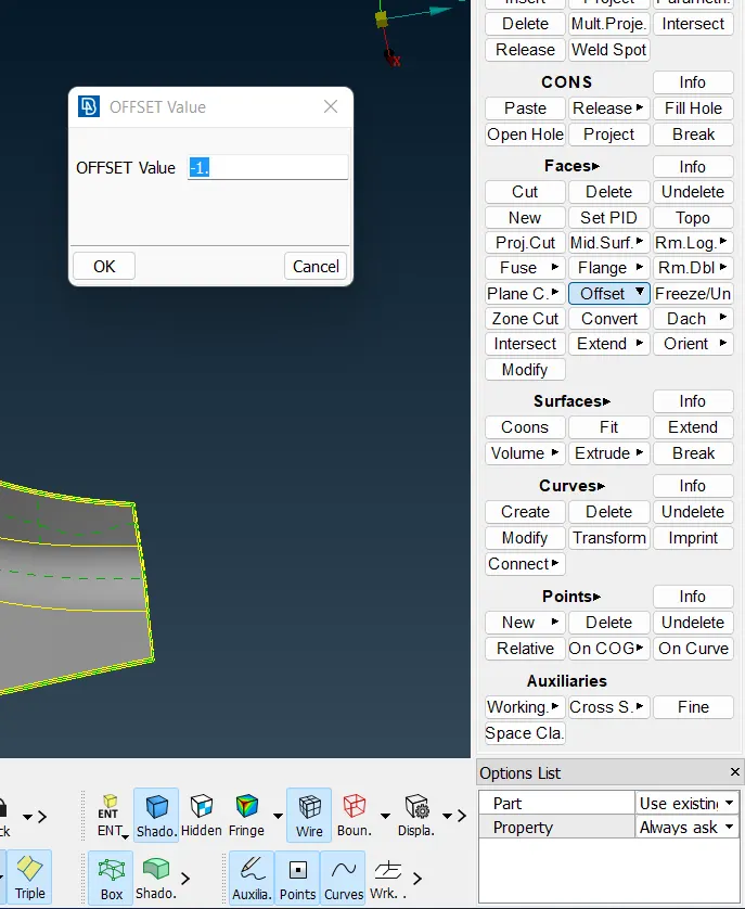
- After the topology has been cleaned up, the next step is to perform the midsurfacing utilising either the offset or middle surface options, depending on the region that is currently being worked on.
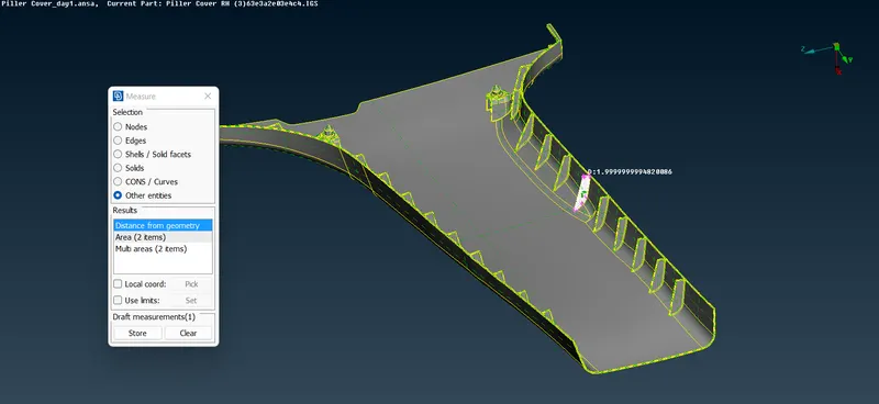
- The offset choice involves taking a measurement of the offset distance and then using that number as part of the calculation for the distance that should be given for the offset procedure. As a result of the manual nature of the midsurfacing process, the surfaces are extracted in groups before being operated on.
-
-
- By using the extend option, the midsurfaces of any ribs in the geometry that do not already intersect with the midsurface of the geometry can be forced to intersect.
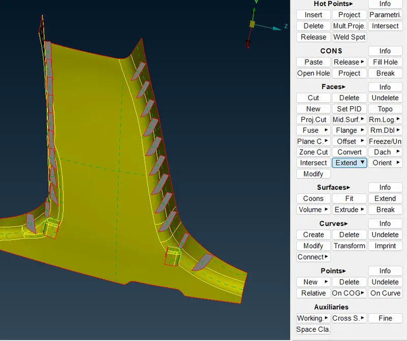
- It is made simple to segregate the extracted midsurface from the rest of the volume by assigning it its own PID.
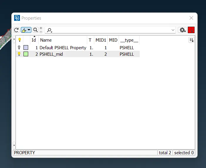
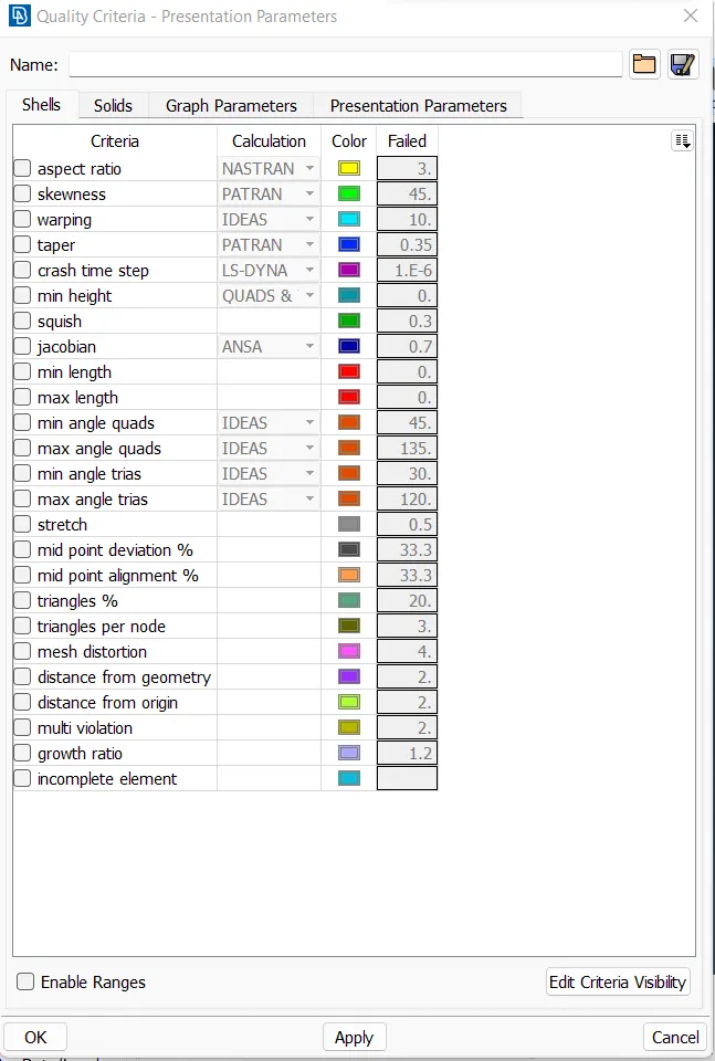
- The midsurface is then provided with the quality requirements and mesh parameters for meshing, as well as the perimeter length, which is the length of the target element.
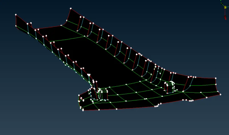
- In order to ensure that the mesh flows as it should, the middle surface has now been separated into areas.
- The meshing process is carried out by utilising the most effective mesh approach, and the mesh flow is recreated if it needs to be reworked.
- The "smooth" option is used to create a finer mesh flow in order to prevent the flow from becoming disrupted as it moves from one region to the next.
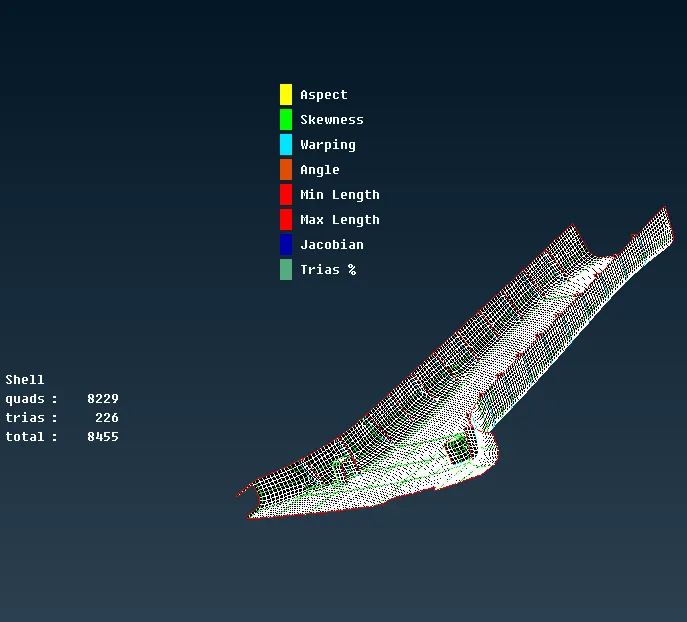
- The model that was provided has been midsurfaced and is now meshing. At long last, a thickness has been allotted to each constituent.
- Therefore, the quality standards that were established have been met for the given model, since it has been successfully completed on midsurfacing and meshing.
-
At the end we need to Release the FE from the Geometry.
Conclusion:-
After the completion of the mesh, the number of tria elements has been determined to be 226, and the number of OFF elements has been determined to be 0.
The result of the learning is:
During this step, we learned how to import the CAD model, how to perform a geometry check-up, how to perform a topo/Geometry cleanup, how to perform the Setting-up of relevant PIDs to different parts, how to select a meshing type, and how to finally generate a surface mesh.