Week - 4
Q.1) Implement control logic of a “washing machine” using Stateflow as per given sequence:
- If the power supply is available, the system gets activated
- If the Water supply is not available, stop the process & indicate through LED
- Soaking time should be 200s followed by Washing time of 100s.
- Then rinsing happens for the next 20s & dryer runs for 50s
Aim: To design the Stateflow sequence diagram for the washing machine on Matlab.
Working of washing machine: The principle behind the working of a washing machine is the centripetal and centrifugal forces. In which centrifugal force help in the process of sedimentation of dirty particle which helps in washing dirty clothes. The working of the washing machine happens in the two-cycle wash cycle and risen cycle. it is capable of handling many tasks like filling water, soaking, washing, rinsing, drying.

Requirement: Matlab.
Stateflow: It provides a graphical interface that includes a transition table, flowchart by using state flow to describe how the Matlab algorithm and Simulink model react to input time-based signals.
Control logic: Control logic is the system logic of the project design using state flow.
Data given:
The different states of a sequence of the washing machines.
- Check the supply is available or the system is activated.
- In case the water supply is not flowing stop the process and indicate using Led and check the level
- Soaking for 200sec(0-200sec)
- Washing for 100sec(200-300sec)
- Rinsing for 20sec(300-320sec)
- Drying for another 50sec.
Procedure:
- Open the Matlab and go to Simulink and save the file in the designated folder, search for chart block by double-clicking on the Simulink window or by searching in the library.
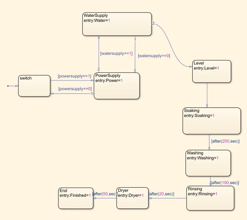
- Using the state block in the chart gives the statement for each and every process by adding a state block.
- Start with the power supply and water supply if both are active then the process continues for the next step or terminate the whole process.
- Given condition for power supply as [Powersupply==1] for On state and [Powersupply==0] for off state and the system terminate.
- Using state block add the statement and with the help of “entry” give the value as 1 for different states.
- In case of soaking, washing, rinsing, drying specific times is given with syntax [after(x.sec) from the comparision[]
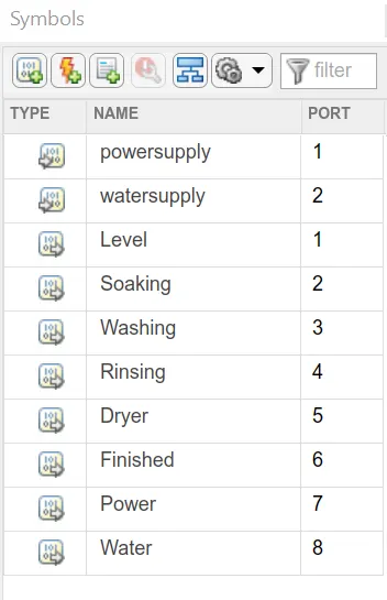
- Now assigned the symbols as input and output depending on state block function.
- As we have two input blocks and eight output blocks connect constant block to input and display block to output blocks.
- Connect the slider switch to the constant block on the input side.
- Connect the LED lamps to all the input and output ports to indicate the condition and position of gear.
CHART:
Symbols Parameter:
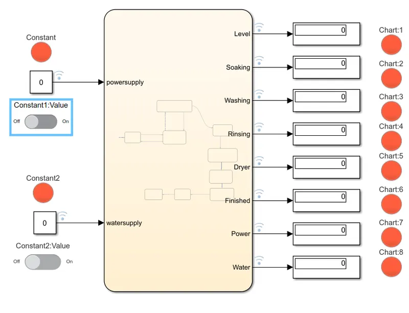
Condition:
1st condition: When The power supply is OFF and hence water supply is also OFF, hence the system is not activated.
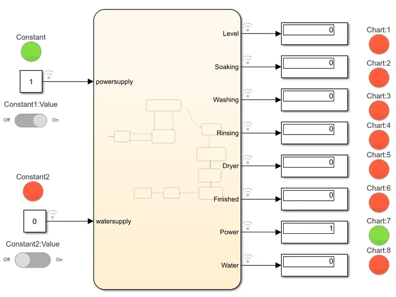
2nd condition: When the power supply is ON and water supply is OFF other processes like soaking, washing, rinsing. does not take place.
3rd condition: the next step is after 100 sec. washing does not start as leveling and soaking take place.
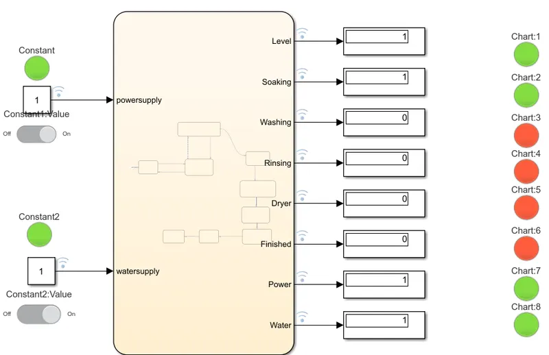
4th condition: the next step is after 200sec when washing gets started and goes for 100 sec and is indicated by LED lamp.
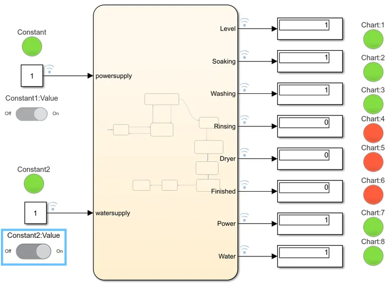
5th condition: rinsing start after 100sec of washing and which goes for 20sec and then dryer run for 50 sec
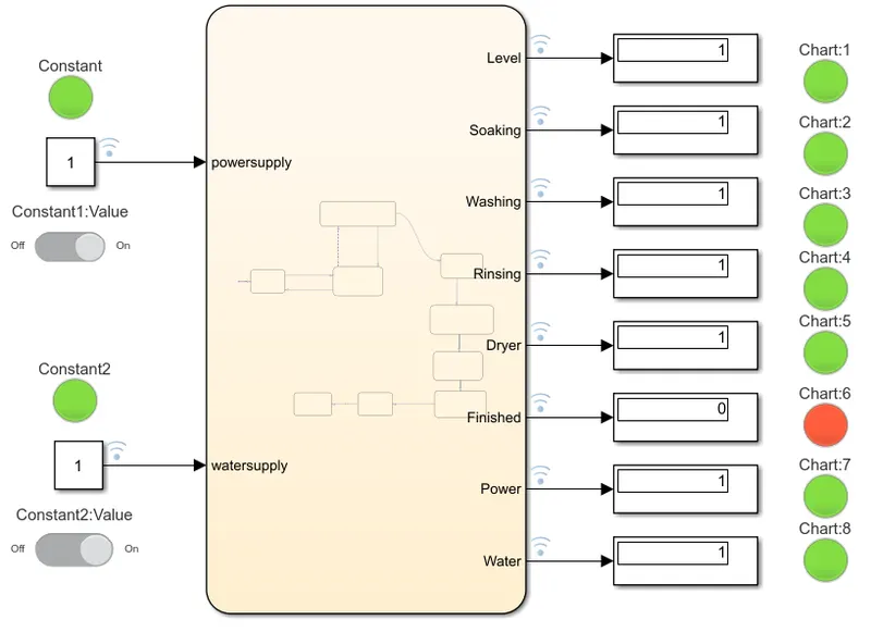
6th condition: After completing all the processes the finish LED lamp is indicated.
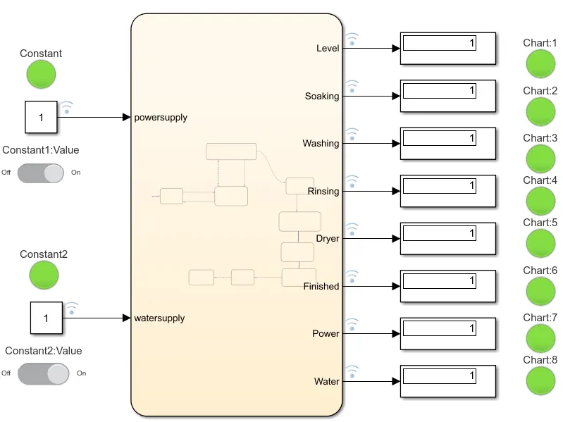
Conclusion: The washing machine mechanism using Stateflow as per the given time interval is simulated and results is shown.
Q.2) Make a Simulink chart for the “Gear shift” logic as per below conditions:
Speed Range(kmph) Gear
0 to 15 1
16 to 25 2
26 to 40 3
41 to 60 4
Above 61 5
Give speed input while the simulation is running & display the gear number.
Ans.
Aim: To design the Stateflow sequence diagram for the Gearbox.
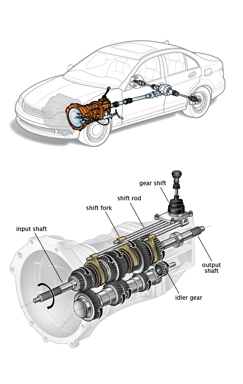
Theory: The gear system determines the amount of power available from the system. Gear systems are divided into four categories depending on the working i.e Automated Manual Transmission(AMT), Continuous Variable Transmission(CVT), Dual Clutch Transmission(DCT), Intelligent Manual Transmission(IMT). A gearbox is also called a transmission box. It is used to adjust the speed and torque generation according to the road and terrain conditions. It changes the engine speed into torque when climbing hill
The function of gearbox:
- Provide torque to vehicle depending on road and load condition. It does this by changing the gear ratio.
- When shifted to reverse gear the vehicle moves backward.
- It should be at neutral gear when starting the engine.
Procedure:
- Open the Matlab and go to Simulink using the library or search window to create a chart block for defining the Stateflow for the condition given.
- Using the state block give the statement for each and every step.
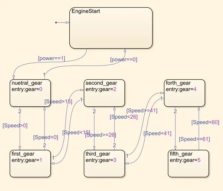
- After joining the state block in a linear manner give conditions as provided above.
- Depending on the speed condition assign the gear number.
- Now assign symbols as input and output as per the requirement to check the output.
- Power and speed are acting like input while gear condition is acting like output.
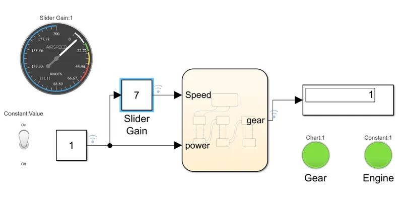
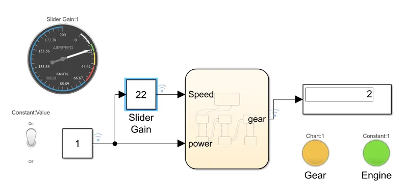
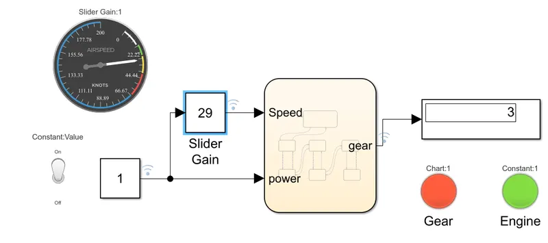
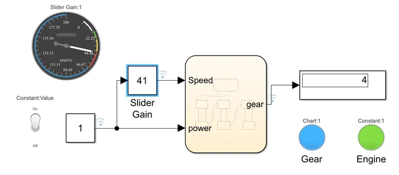
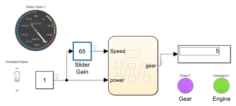
- Connect the constant block to power input, gain slider block to speed input, and display block to gear output.
- Connect toggle switch to constant power block and speedometer to speed input slider.
- Using LED lamp indicator assign different colors for different gears and connect it to display block and same in case of engine ignition power block.
- Run the system for different speed conditions and check the display and Led lamp indicator
Stateflow:
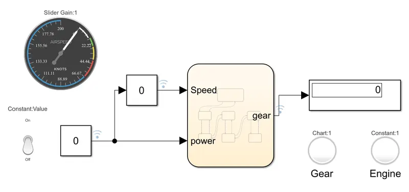
Input #1:
Ignition is OFF and speed is also 0
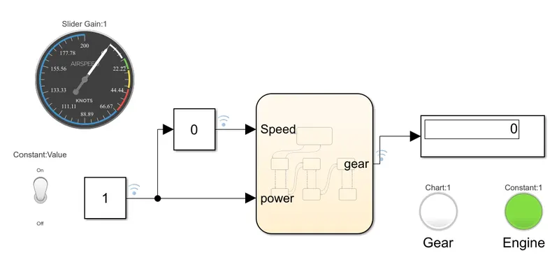
Input #2:
Ignition is ON but the speed is still 0, engine LED lamp indicates green color.
Input #3:
Ignition is ON and speed is increase from 0 to 15 and the output is shown in the display as 1 and LED lamp to indicate green.
Input #4:
Ignition is ON and speed is increase from 16 to 25 and the output is shown in the display as 2 and LED lamp indicates yellow.
Input #5:
Ignition is ON and speed is increase from 26 to 40 and the output is shown in the display as 3 and LED lamp indicates orange.
Input #6:
Ignition is ON and speed is increase from 41 to 60 and the output is shown in the display as 4 and LED lamp indicates blue.
Input #7:
Ignition is ON and speed is increase above 61 and the output is shown in the display as 5 and LED lamp indicates purple.
Conclusion:
The gear shift mechanism and execution of Stateflow for a given condition is simulated and results is shown.