Project 1 (Mini Project on Vehicle Direction Detection
Mini Project - Vehicle Direction Determination For ADAS
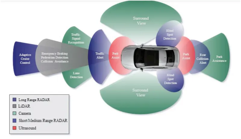
Advanced driver-assistance systems (ADAS) are one of the fastest-developing protection utility areas because of the choice to reduce vehicular accidents and fatalities. Beyond passive protection structures, active safety structures play a prime role in reducing traffic fatalities and the economic effect of vehicular accidents. ADAS structures consist of long- and medium-variety radar and vision structures. Developing an ADAS system need for contemporary but value-effective RF generation that may be embedded withinside the automobile for outside item detection and classification. A contemporary radar device can inform a automobile from a pedestrian, from a wall, and realize the area and potential corrective path. Extraordinary computation energy is required to make the device efficient, however to grow to be greater accepted withinside the market the price ought to be very low. Active protection structures consist of adaptive cruise control (ACC) and collision-warning structures with computerized guidance and braking intervention. In a collision-warning device, a microcontroller-managed 77 GHz transmitter emits indicators reflected from objects ahead, to the side and to the rear of the automobile, which can be captured via way of means of more than one receivers incorporated at some stage in the automobile. Using a high-overall performance 32-bit single- or dual-core microcontroller with embedded flash and RAM, the radar device can locate and tune items withinside the frequency domain, triggering a motive force caution of an coming near near collision and starting up ESC emergency.
General Overview:
Identifying the direction of the vehicle is one of the important & diverse features in Autonomous driving & Advanced Driver Assistance Features. This particular sub-feature of identifying the direction of the vehicle is basically identifying the direction the vehicle is taking based on the camera input.
The camera reads the road signs & stores them into its memory with unique values for a left turn, right turn & straight drive. Depending on the direction it is taking, the final indication is given to the driver – as an indication if he is driving in the recommended direction or not.
Vehicle Direction Determination can also be coupled alongside features like GPS systems to identify whether the vehicle is reaching its destination in an optimized manner. This sub-feature can also be used along with Lane Detection, Highway Warning, Ramp Entry / Exit in Wrong Way Detection, etc.
Requirement - 1:
- Steering wheel input as yaw rate (Signal name: SteeringWheel_YawDegreeInput) is the input for this system.
- This is compared against 3 angular values, one each for a left turn, right turn & straight drive (Calibration Values: Right_Turn_AngularLimit, Left_Turn_AngularLimit, Straight_Drive_Steering_Angle) to say which specific direction the steering wheel is turning towards.
- Use switch blocks to compare & develop this requirement. Keep this requirement in a subsystem & the output of this requirement is a local signal (Signal Name: Vehicle_Turn_Status).
Given Task:
- The input to the system are Steering wheel angular input given as yaw rate
(Signal name: SteeringWheel_YawDegreeInput) and an input signal from the camera (Signal name:
SteeringWheel_RoadSign), which confirms the occurrence of a road sign.
- A camera reads the road signs & stores into its memory unique values for a left turn, right turn & straight drive. Depending on the direction the vehicle takes. a final indication is given to the driver if he driving in the recommended direction or not
- The output of the system is a Boolean value( Signal Name: Vehicle_Direction_Indicator) which specifies whether the vehicle is turning right, left, or going straight
Signals & Calibration Data List:
|
Signal / Calibration Name |
Signal Type |
Data Type |
Dimension |
Min |
Max |
Initial Value |
Units |
|
SteeringWheel_YawDegreeInput |
Input |
Int16 |
1 |
-180 |
180 |
- |
Deg |
|
Vehicle_Turn_Status |
Local |
Int16 |
1 |
-180 |
180 |
- |
Deg |
|
Right_Turn_AngularLimit |
Calibration |
Int16 |
[1 1] |
-180 |
180 |
30 |
Deg |
|
Left_Turn_AngularLimit |
Calibration |
Int16 |
[1 1] |
-180 |
180 |
-120 |
Deg |
|
Straight_Drive_Steering_Angle |
Calibration |
Int16 |
[1 1] |
-180 |
180 |
0 |
Deg |
Creating Simulink data dictionary (SLDD) for the project
Simulink Data Dictionary(SLDD): MathWorks introduced a new feature in 2014 that is called Simulink Data Dictionary. This new feature provides the ability to save data types, parameters, and signals to database files. This is good news for embedded developers who need flexibility in using data objects and don't want to use the default workspace, which can lead to data corruption. In the initial implementation, the data dictionary interface is provided by the Simulink Model Explorer. The GUI is clean, intuitive, and easy to use. It helps in importing and exporting dictionaries to m-files and mat-files.
The Simulink data dictionary, also known as SLDD, exists as a file with the standard file extension .sldd. The dictionary file can be opened with the open function that calls opensldd. This will open the file and launch Simulink Model Explorer on the selected dictionary node.
Data dictionaries allow you to customize model code generation for a variety of purposes by simply changing the dictionary you are using.
here we are going to make an SLDD file using the data provided for signals and constant
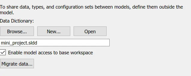
Go to Model properties > click on the external Data>create a new file with .sldd extension> save the file
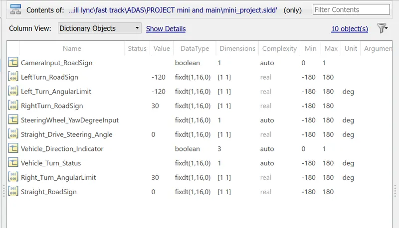
Add Simulink signal for adding input, output, and local signals and using Simulink parameter for adding constant data.
-give the value for maximum and minimum along with the data type if required change resolution as asked.
DEVELOPMENT OF SIMULINK MODEL FOR REQUIREMENT 1
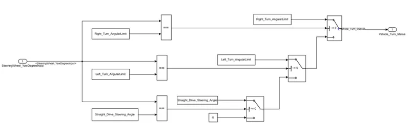
The Input is given to the relational operator as a (Signal name: SteeringWheel_YawDegreeInput) which is then compared with SteeringWheel_YawDegreeInput if the condition satisfy the output is given as 1 which is more than the threshold value of switch The output is given as Right_turn_Angularlimit which will be Vehicle_Turn_Status output and if the condition is not satisfied and threshold value is equal to the output of relational operator than the condition check for another condition i:e(Left_Turn_AngularLimit) if this input is compared with Left_Turn_AngularLimit and the output is positive than the value given to Vehicle_Turn_Status as Left_Turn_AngularLimit and if the output of the relational operator is not great than a threshold value which is 0 then the signal will be check with Straight_Drive_Steering_Angle using relational operator if the values match then we have output as 1 which is greater than the threshold value then the output of Vehicle_Turn_Status is Straight_Drive_Steering_Angle
If all the condition don’t satisfy then the vehicle run in the same direction and the output is 0
GIVEN REQUIREMENT: 2
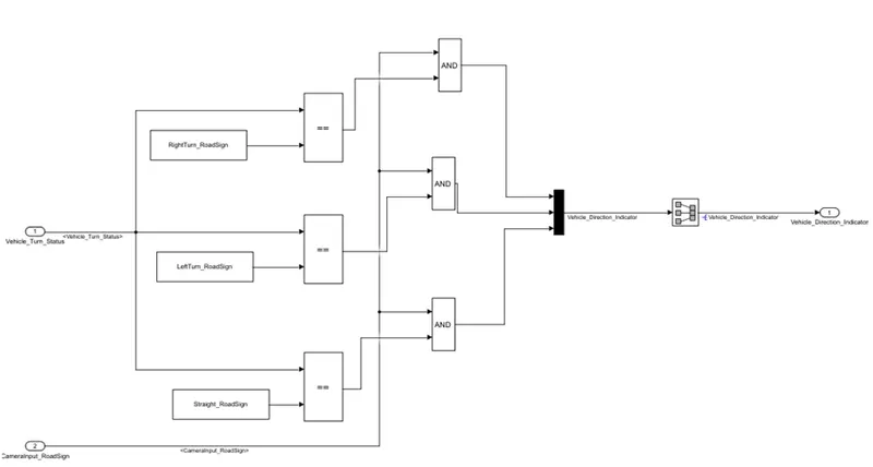
- Keep this requirement as a separate subsystem. Inputs to this requirement are a local signal from requirement 1 (Signal Name: Vehicle_Turn_Status) & an input signal from the camera (Signal Name: CameraInput_RoadSign), which confirms the occurrence of a road sign.
- Signal Vehicle_Turn_Statusis compared against calibration values (Calibration Values: RightTurn_RoadSign, LeftTurn_RoadSign, Straight_RoadSign), if each of them is found equal, then each of the three corresponding output is compared against the camera input signal,
- Using a logical operator block, only one among them is finally given as output signal (Signal Name: Vehicle_Direction_Indicator).
- Signals & Calibration Data List:
|
Signal / Calibration Name |
Signal Type |
Data Type |
Dimension |
Min |
Max |
Initial Value |
Units |
|
SteeringWheel_YawDegreeInput |
Input |
Int16 |
1 |
-180 |
180 |
- |
Deg |
|
CameraInput_RoadSign |
Input |
Boolean |
1 |
0 |
1 |
- |
- |
|
Vehicle_Turn_Status |
Local |
Int16 |
1 |
-180 |
180 |
- |
Deg |
|
Right_Turn_AngularLimit |
Calibration |
Int16 |
[1 1] |
-180 |
180 |
30 |
Deg |
|
Left_Turn_AngularLimit |
Calibration |
Int16 |
[1 1] |
-180 |
180 |
-120 |
Deg |
|
Straight_Drive_Steering_Angle |
Calibration |
Int16 |
[1 1] |
-180 |
180 |
0 |
Deg |
|
RightTurn_RoadSign |
Calibration |
Int16 |
[1 1] |
-180 |
180 |
30 |
|
|
LeftTurn_RoadSign |
Calibration |
Int16 |
[1 1] |
-180 |
180 |
-120 |
|
|
Straight_RoadSign |
Calibration |
Int16 |
[1 1] |
-180 |
180 |
0 |
|
|
Vehicle_Direction_Indicator |
Output |
Boolean |
1 |
0 |
1 |
- |
- |
DEVELOPMENT OF SIMULINK MODEL FOR REQUIREMENT:2
This is another subsystem with the input to this requirement are a local signal from requirement 1
(Signal Name: Vehicle_Turn_Status ) and we also have a camera which detects the signal and stores the information
in unique value
- The input signal is given as (Signal Name: CameraInput_RoadSign) which is given to AND logical operator which is compared by the output from Vehicle_Turn_Status that is compared with RightTurn_RoadSign value if both the condition satisfy and the condition is positive then the output is given and is also compared with logical == operator than the output is given by Vehicle_Direction_Indicator And with the help of signal conversion signal the signal is given as output.
- The input signal is given as (Signal Name: CameraInput_RoadSign) which is given to AND logical operator which is compared by the output from Vehicle_Turn_Status that is compared with LeftTurn_RoadSign value if both the condition satisfy and the condition is positive then the output is given and is also compared with logical == operator than the output is given by Vehicle_Direction_Indicator And with the help of signal conversion signal the signal is given as output.
- The input signal is given as (Signal Name: CameraInput_RoadSign) which is given to AND logical operator which is compared by the output from Vehicle_Turn_Status that is compared with Straight_RoadSign value if both the condition satisfy and the condition is positive then the output is compared with logical == operator than the output is given by Vehicle_Direction_Indicator And with the help of signal conversion signal the signal is given as output.
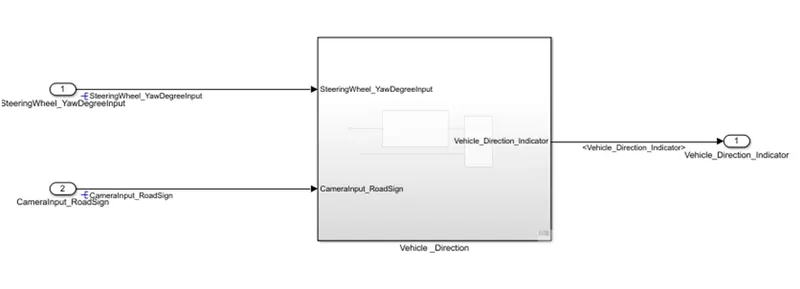
DEVELOPMENT OF THE SIMULINK MAIN MODEL:
The main subsystem ‘Vehicle_Direction’along with input ‘SteeringWheel_YawDegreeInput’
‘CameraInput_RoadSign’ and output signal’Vehicle_Directioin_indicator’ are shown below.
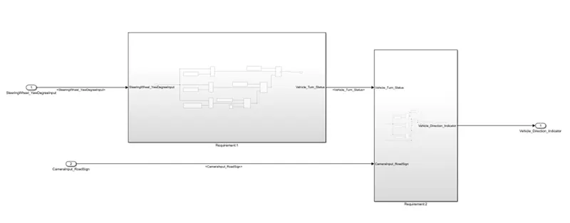
The main subsystem ‘Vehicle_Direction’ is further divided into two more subsystems which is ‘Requirement1’ and ‘Requirement2’ as shown below:
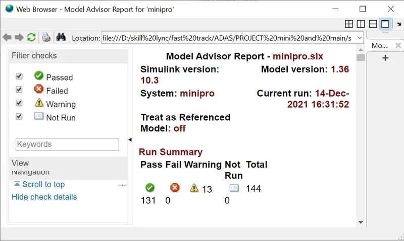
Model Advisor Report
The Model Advisor tests the version or subsystem to see the modeling situation and configuration settings that make the simulation of the machine that the version represents incorrect or inefficient. Model Advisor testing helps ensure compliance with business requirements and tips. Model Advisors allow initiatives and improvement teams to enable certain modeling tips. Once the version has been evaluated, the Model Advisor will create a document that lists the suboptimal situations, settings, and modeling strategies and suggests solutions as needed.
You can use the Model Advisor to test the version in the following ways:
- Model AdvisorPerform Tests Interactively Configure Model Advisor to run turnaround time tests mechanically (call Simulink ® Check ™)
- Interactively run Model Advisor checks
DOCUMENTATION TAGGING TO SIMULINK SUBSYSTEM
- Make a word file that needs to be tagged and save it in the same folder as the Simulink file.
- Select the text that has the same content and description for the subsystem block.
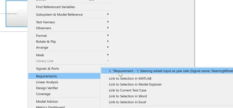
- Right-click on the subsystem block go to requirement click on the link to selection in word
Model-in-the-loop (MIL) simulation or model-based testing First, you need to extend the actual system (hardware) version in a simulation environment that includes Simulink, which maximizes the critical functionality of your hardware system. Once the system version is created, expand the control version to see if the control can manage the system (in this case the motor version) according to your requirements. This step is called Model-in-Loop (MIL) and confirms the common sense of the controller in the simulated version of the plant. If the controller is functioning as expected, you should report the controller's inputs and outputs for later verification levels.
Steps to create a test harness from the template for MIL testing:
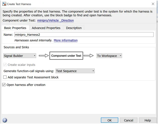
- Create test harness by right-clicking on subsystem and going to Test Harness>Create harness for the subsystem.
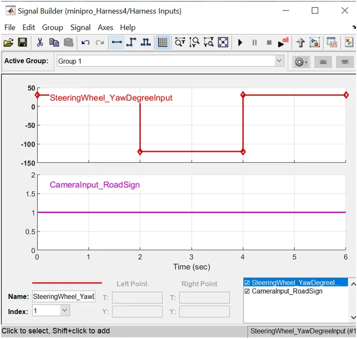
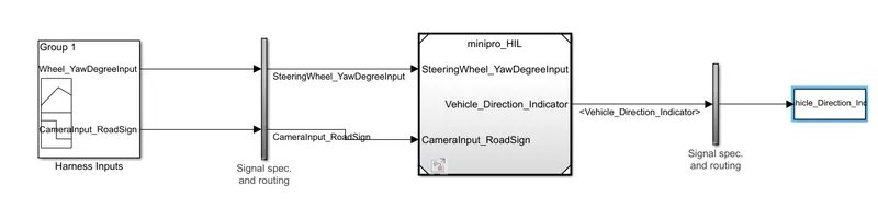
Giving the values to signal builder as per given in the table