Project 2 Adaptive Cruise Control
Project 2 Adaptive Cruise Control
With the help of a driver assistance system (ADAS) Possibility to improve traffic safety, reduce traffic load and improve traffic efficiency. Extensive research on ADAS control strategies such as adaptive cruise control Systems, Lane Departure Warning systems, Automatic Emergency Braking systems The functionality of such systems, has been thoroughly investigated and certified. Continue Improvement of anthropomorphism should also flow into the development of these systems. Human-like driving behavior patterns can improve driving comfort Increase user trust, improve user acceptance, and increase the frequency of use. Meanwhile, the surrounding drivers were able to better understand the adaptive vehicle. Natural interactions between human-like driving patterns and a mixture of humans and robots Traffic environment. With the development of human-like ADAS, A need for testing and evaluation methods that take into account human-like behavior. The moving state of the preceding vehicle and the own vehicle Command from a human driver, automatically controlled by the Adaptive Cruise Control System (ACC) Provides drivers with information about the vertical movement of private cars and driving risks To reduce the power of driving tasks and ensure driving safety. Currently, the ACC system is widely used. In 2018, about 11.8% of all models were equipped with ACC. Wearing System as an American standard configuration. As a mature feature already on the market, some test standards or Regulations for the ACC system are ISO, SAE, GB, FMCSA etc.
ISO 15622 and GB / T 20608 share three similar basic tests Procedure:
Target detection area test, target identification test, cornering ability Test in three test scenarios. Also, delay capability test scenarios Part of the system is supplemented with SAEJ2399. All of these related standards focus on testing Function, d. H. Whether it is a function such as vertical range or speed Control was realized. On the other hand, research on ACC system and ADAS test/evaluation method The main focus are on security. Literal. Evaluate the effect of the ACC parameter To reduce the risk of collisions on busy highways. Qiu et al. Proposed a model of Assessment of ADAS system accident probability From a security point of view. Focus on collision avoidance, Stark etc. Run the simulation The latest ADAS performance. These criteria and studies on testing and evaluation methods from ACC The system has been very successful in evaluating the system, but none of them. Be considerate of human-like behavior. Therefore, I suggested in this post How to test and evaluate ACC systems, including both security and human-like Power.
This method has two advantages:
- This ready-made method Provides test scenarios generated from actual driving data, The actual implementation environment.
- Results are evaluated quantitatively from both Security and a human-like perspective. This work improves existing tests Evaluation methods from the viewpoint of a more realistic and efficient test scenario set etc. Comprehensive metrics that are very important for further improvement Overview of the ACC System
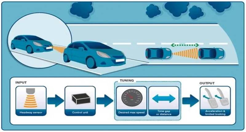
Driving in heavy traffic and maintaining a safe distance from the vehicle in front requires a high degree of concentration. Adaptive Cruise Control (ACC) automatically adjusts the vehicle speed and releases the driver by maintaining a predefined minimum distance from the vehicle in front. As a result, the driver is more comfortable and can focus on the traffic.
A radar sensor is usually at the core of the Adaptive Cruise Control. Installed at the front of the vehicle, the system permanently monitors the road ahead. As long as the road ahead is clear, cruise control feature maintains the speed set by the driver. If the system spots a slower vehicle within its detection range, it gently reduces speed by releasing the accelerator or actively engaging the brake control system. If the vehicle ahead speeds up or changes lanes, the cruise control automatically accelerates to the driver’s desired speed.
Standard Adaptive Cruise Control can be activated from speeds of around 30 km/h (20 mph) upwards and supports the driver, primarily on cross-country journeys or on freeways. The cruise control stop & go variant is also active at speeds below 30 km/h (20 mph). It can maintain the set distance to the preceding vehicle even at very low speeds and can decelerate to a complete standstill. When the vehicle remains stopped longer, the driver needs only to reactivate the system, for example by briefly stepping on the gas pedal to return to cruise control mode. In this way, cruise control stop & go supports the driver even in heavy traffic and traffic jams.
Since Adaptive Cruise Control is a comfort and convenience system, brake interventions and vehicle acceleration only take place within defined limits. Even with Adaptive Cruise Control switched on, it remains the driver’s responsibility to monitor the speed and distance from the vehicle in front.
Objective of Main Project:
- Developing Adaptive Cruise Control feature as per the Requirement Document using MATLAB Simulink.
- Follow all the MBD related processes: Requirement Tagging & Traceability, SLDD creation, Configuration Parameter changes, Model Advisor check & Code Generation.
- In Configuration Parameters: enable “Support Floating Numbers” under Code Generation settings.
- Use Embedded Coder to generate the code.
- If choosing code generation, Storage class for Input signals: ImportedExtern; Storage class for Output signal: Export to File; Storage class for local signals: localizable; Storage class for calibration signals: Const.
- Choose sample time for all signals as 0.01s
Simulink Data Dictionary(SLDD): MathWorks introduced a new feature in 2014 that is called Simulink Data Dictionary. This new feature provides the ability to save data types, parameters, and signals to database files. This is good news for embedded developers who need flexibility in using data objects and don't want to use the default workspace, which can lead to data corruption. In the initial implementation, the data dictionary interface is provided by the Simulink Model Explorer. The GUI is clean, intuitive, and easy to use. It helps in importing and exporting dictionaries to m-files and mat-files.
The Simulink data dictionary, also known as SLDD, exists as a file with the standard file extension .sldd. The dictionary file can be opened with the open function that calls opensldd. This will open the file and launch Simulink Model Explorer on the selected dictionary node.
The dictionary file changes only if the changes are saved with the appropriate command. You can add elements to the dictionary by creating a model, default workspace, or new element in the Model Explorer. You can pre-link a Simulink model using the Model Properties drop-down menu in the Simulink Editor. Data dictionaries allow you to customize model code generation for a variety of purposes by simply changing the dictionary you are using.
here we are going to make a SLDD file using the data provided for signals and constant
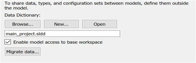
Go to Model properties > click on the external Data>create a new file with .sldd extension> save the file
- Add Simulink signal for adding input, output and local signals and using simulink parameter for adding constant data, give the value for maximum and minimum along with the data type if required change resolution as asked.
Signals & Calibration Data List:
|
Signal / Calibration Name |
Signal Type |
Data Type |
Dimension |
Min |
Max |
Initial Value |
Units |
|
CameraInput_LeadVehicle |
Input |
Uint8 |
1 |
0 |
255 |
- |
- |
|
RadarInput_LeadVehicle |
Input |
Uint8 |
1 |
0 |
255 |
- |
- |
|
CameraInput_DriveVehicle |
Input |
Uint8 |
1 |
0 |
255 |
- |
- |
|
RadarInput_DriveVehicle |
Input |
Uint8 |
1 |
0 |
255 |
- |
- |
|
Time_Gap |
Input |
Uint8 |
1 |
0 |
255 |
- |
- |
|
Set_Speed |
Input |
Uint8 |
1 |
0 |
255 |
- |
- |
|
Set_Gap |
Input |
Uint8 |
1 |
0 |
255 |
- |
- |
|
CruiseSwitch |
Input |
Boolean |
1 |
0 |
1 |
- |
- |
|
SetSwitch |
Input |
Boolean |
1 |
0 |
1 |
- |
- |
|
Acceleration_Mode |
Output |
Uint8 |
1 |
0 |
255 |
- |
- |
|
LeadVehicle_Speed |
Output |
Uint8 |
1 |
0 |
255 |
- |
- |
|
DriveVehicle_Speed |
Output |
Uint8 |
1 |
0 |
255 |
- |
- |
|
LeadVehicle_Detected |
Output |
Uint8 |
1 |
0 |
255 |
- |
- |
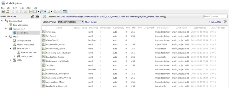
- Save after putting all the data and link with the simulink file
Requirement 1– Lead Vehicle:
- Lead Vehicle is a vehicle which is driving in the road ahead of our drive vehicle. Two input signals (Signal Name: CameraInput_LeadVehicle & RadarInput_LeadVehicle).
- Ideally sensor fusion techniques will be deployed to process & analyze data from camera & radar. For complexity reasons, let’s not adapt to any such algorithms.
- We can simply add both the radar & camera inputs & the corresponding output is read as Speed profile output (Signal Name: LeadVehicle_Speed).
- Speed data of the lead vehicle is critical in implementing the Adaptive Cruise Control algorithm.
Designing of simulink model for requirement1
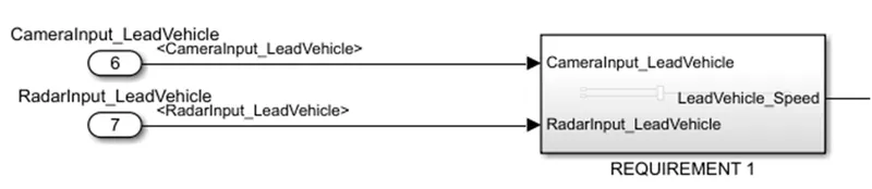
Inside the REQUIREMENT1 block:
- The Signals (CameraInput_LeadVehicle & RadarInput_LeadVehicle ) are connected on the vehicle and the input is in the form of fusion technique.
- Here we simply Add both radar and camera input and we get output signal as (Signal Name: LeadVehicle_Speed). Which is critical in implementing the Adaptive Cruize Control Algorithm

Requirement 2 – Drive Vehicle:
- Drive Vehicle is the vehicle driven by the user & this is the vehicle which has ACC algorithm in it.
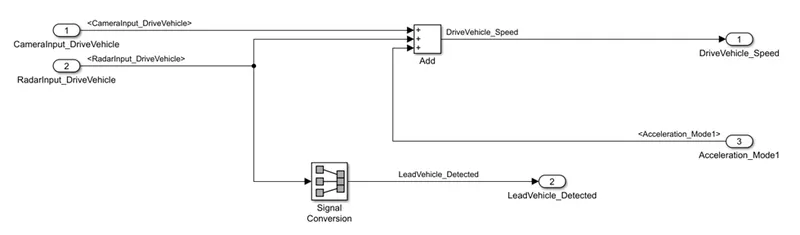
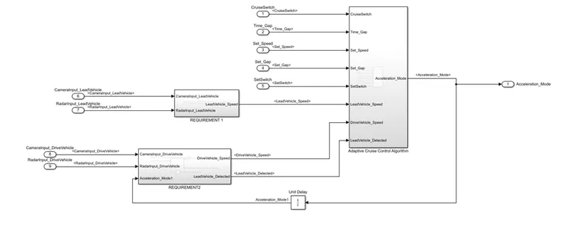
- Like the Lead Vehicle, Drive Vehicle algorithm also has 2 input signals (Signal Name: CameraInput_DriveVehicle, RadarInput_DriveVehicle) & one signal coming as an Input to this subsystem (Signal Name: Acceleration_Mode) – three inputs into this requirement in total.
- Like the above requirement, sensor fusion techniques will also be deployed here, for complexity reasons we are ignoring them.
- Two output signals come from this subsystem (Signal Name: DriveVehicle_Speed & LeadVehicle_Detected).
- Signal DriveVehicle_Speed is summation of three input signals mentioned above & LeadVehicle_Detected is renamed from Input Signal RadarInput_DriveVehicle by mere use of Signal Conversion block.
Inside the REQUIREMENT2 block:
- The Signals (CameraInput_DriveVehicle & RadarInput_DriveVehicle ) are connected to the vehicle and the input is in the form of fusion technique. & one signal coming From the ACC block using a unit delay. This is the vehicle that has ACC algorithm in it.
- We Get two output signals from this subsystem with (Signal Name: DriveVehicle_Speed & LeadVehicle_Detected).
- The output signal DriveVehicle_Speed is summation of three input signals mentioned above & Lead vehicle is renamed from input Signal RadarInput_DriveVehicle by mere use of signal conversion block

Requirement 3 – Adaptive Cruise Control Algorithm:
- Adaptive Cruise Control feature has 3 major modes of operation: OFF Mode, STANDBY Mode & ON Mode. This particular requirement has to be implemented as state machine logic in Simulink.
- The input signals to this state machine system are (Signal Name: Time_Gap, Set_Speed, Set_Gap, CruiseSwitch, SetSwitch).
- Also, the output signals (Signal Name: DriveVehicle_Speed & LeadVehicle_Detected) from requirement-2 is fed back as an input signal into this state machine block.
- Additionally, output signal (Signal Name: LeadVehicle_Speed) from requirement1 is given as an input signal to this state machine block as well.
- Output from this subsystem is a signal (Signal Name: Acceleration_Mode) which governs the vehicular speed of the drive vehicle which automatically adjusts its speed & velocity to match the lead vehicle.
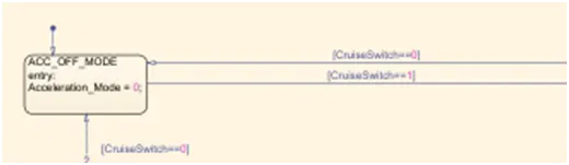
Requirement 3a – ACC OFF MODE state logic:
- This is the default state inside state machine logic. Output signal Acceleration_Mode = 0 in this state.
- This state is governed by input signal CruiseSwitch.
- If CruiseSwitch is equal to 1, state ACC STANDBY mode will get activated. If CruiseSwitch is equal to 0, state ACC OFF mode will get activated, from either ACC ON mode or ACC STANDBY mode
Requirement 3b – ACC STANDBY MODE state logic:
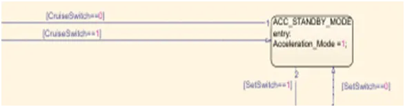
- This is the second activated state inside state machine logic. Output signal Acceleration_Mode is at value 1 in this state.
- This state is governed by both input signals CruiseSwitch & SetSwitch.
- If CruiseSwitch is equal to 1, state ACC STANDBY mode will get activated. If CruiseSwitch is equal to 0, state ACC OFF mode will get activated, from either ACC ON mode or ACC STANDBY mode
Requirement 3c – ACC ON MODE state logic:
This state will be activated when input signal SetSwitch is equal to 1. There are 6 sub states to this state logic: They are:
- LeadVehicle_Detected_Follow (Default)
- LeadVehicle_Not_Detected
- LeadVehicle_Detected_Resume
- LeadVehicle_Not_Detected_Resume
- LeadVehicle_Speed_lessthan_Set_Speed
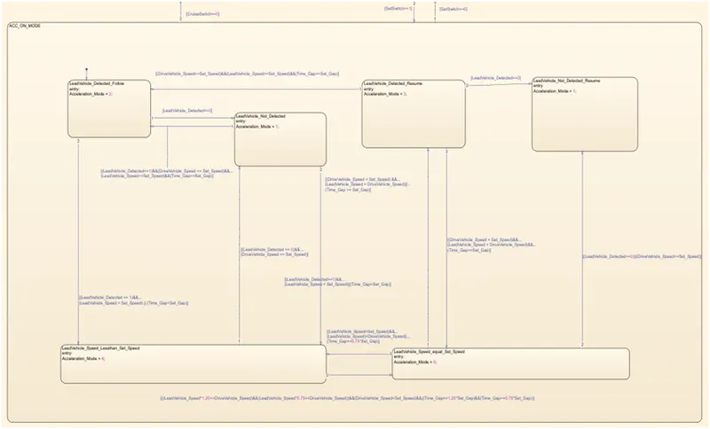
Requirement 3c (i) – LeadVehicle_Detected_Follow (ACC ON MODE):
- This is the default sub state inside ACC ON MODE state. Output signal Acceleration_Mode = 2.
- Condition to transit from LeadVehicle_Detected_Follow to LeadVehicle_Not_Detected; Input signal condition LeadVehicle_Detected == 0.
- Condition to transit from LeadVehicle_Detected_Follow to LeadVehicle_Speed_lessthan_Set_Speed; Input Signals condition (LeadVehicle_Detected == 1) && (LeadVehicle_Speed < Set_Speed) || (Time_Gap < Set_Gap).
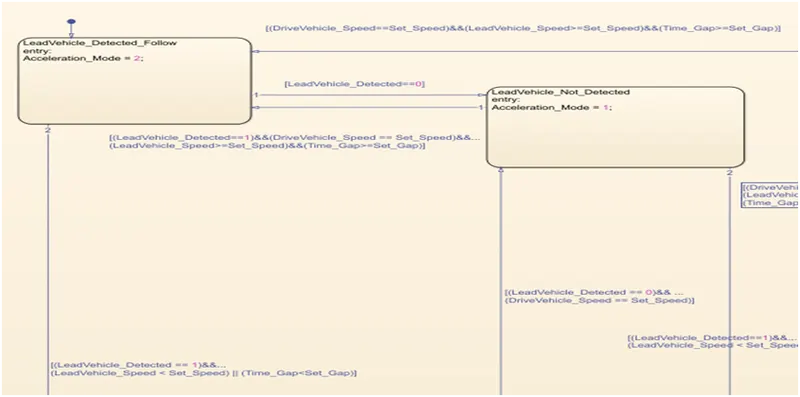
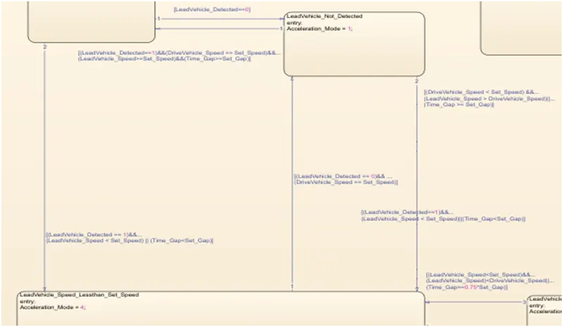
Requirement 3c (ii) – LeadVehicle_Not_Detected (ACC ON MODE):
- Output signal Acceleration_Mode is equal to 1.
- Condition to transit from LeadVehicle_Not_Detected to LeadVehicle_Detected_Follow; Input signals condition [(LeadVehicle_Detected==1) && (DriveVehicle_Speed == Set_Speed) && (LeadVehicle_Speed >= Set_Speed) && (Time_Gap >= Set_Gap)]
- Condition to transit from LeadVehicle_Not_Detected to LeadVehicle_Speed_lessthan_Set_Speed; Input signals condition [(LeadVehicle_Detected == 1) && (LeadVehicle_Speed < Set_Speed) || (Time_Gap < Set_Gap)]
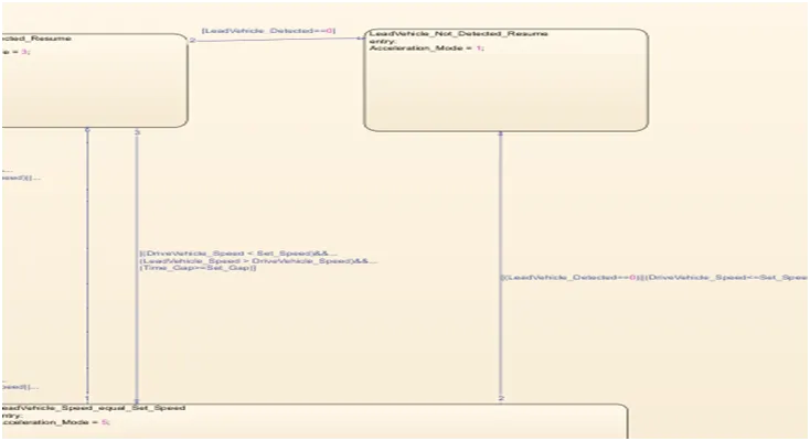
Requirement 3c (iii) – LeadVehicle_Detected_Resume (ACC ON MODE):
- Output signal Acceleration_Mode = 3.
- Condition to transit from LeadVehicle_Detected_Resume to LeadVehicle_Detected_Follow; Input signals condition [(DriveVehicle_Speed == Set_Speed) && (LeadVehicle_Speed >= Set_Speed) && (Time_Gap >= Set_Gap)]
- Condition to transit from LeadVehicle_Detected_Resume to LeadVehicle_Not_Detected_Resume; Input signal condition LeadVehicle_Detected==0.
- Condition to transit from LeadVehicle_Detected_Resume to LeadVehicle_Speed_equal_Set_Speed; Input Signal condition [(DriveVehicle_Speed < Set_Speed) && (LeadVehicle_Speed > DriveVehicle_Speed) && (Time_Gap >= Set_Gap)]
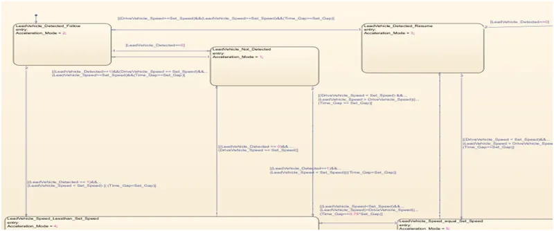
Requirement 3c (iv) - LeadVehicle_Not_Detected_Resume (ACC ON MODE):
- Output signal Acceleration_Mode = 1.
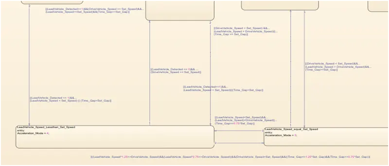
Requirement 3c (v) - LeadVehicle_Speed_lessthan_Set_Speed (ACC ON MODE):
- Output signal Acceleration_Mode: 4.
- Condition to transit from LeadVehicle_Speed_lessthan_Set_Speed to LeadVehicle_Not_Detected; Input signal condition [(LeadVehicle_Detected == 0) && (DriveVehicle_Speed == Set_Speed)]
- Condition to transit from LeadVehicle_Speed_lessthan_Set_Speed to LeadVehicle_Speed_equal_Set_Speed; Input signals condition [((LeadVehicle_Speed*1.25>=DriveVehicle_Speed) && (LeadVehicle_Speed * 0.75<=DriveVehicle_Speed)) && (DriveVehicle_Speed < Set_Speed) && ((Time_Gap<=1.25*Set_Gap) && (Time_Gap >=0.75*Set_Gap))]
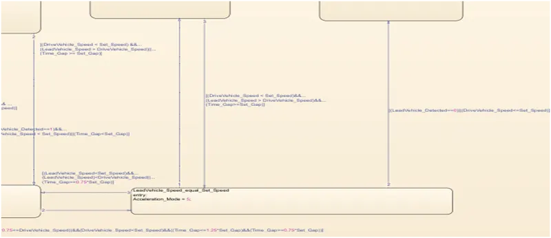
Requirement 3c (vi) - LeadVehicle_Speed_equal_Set_Speed (ACC ON MODE):
- Output signal Acceleration_Mode = 5.
- Condition to transit from LeadVehicle_Speed_equal_Set_Speed to LeadVehicle_Not_Detected_Resume; Input signal conditions is [(LeadVehicle_Detected == 0) || (DriveVehicle_Speed <= Set_Speed)]
- Condition to transit from LeadVehicle_Speed_equal_Set_Speed to LeadVehicle_Detected_Resume; Input signal conditions [(DriveVehicle_Speed < Set_Speed) && (LeadVehicle_Speed > DriveVehicle_Speed) || (Time_Gap >= Set_Gap)]
- Condition to transit fromLeadVehicle_Speed_equal_Set_Speed to LeadVehicle_Speed_lessthan_Set_Speed
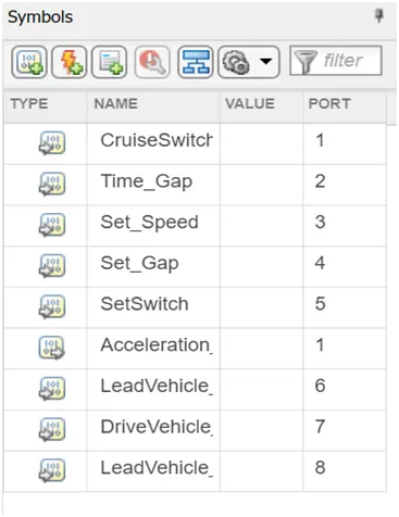
Giving input and output for the ACC(Adaptive Cruise Control) algorithm:
- Open the Symbols pane from the simulation tab and designate the Symbols as input or output
- Give the port number as you find it suitable.
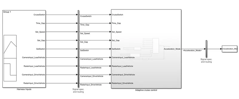
Requirement3 –Adaptive Cruise Control Algorithm
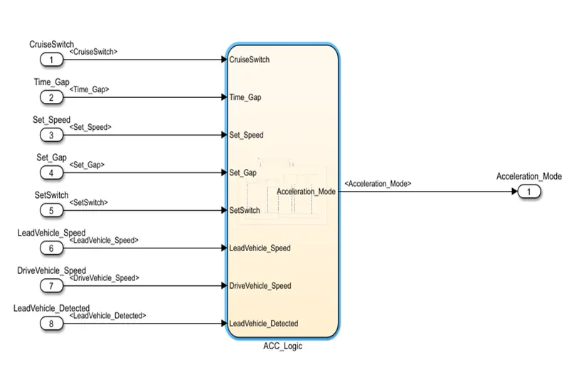
Inside the Adaptive cruise control block we have Requirement1, Requirement2 and Adaptive Cruise Control Algorithm:
Model Advisor Report
The Model Advisor tests the version or subsystem to see the modeling situation and configuration settings that make the simulation of the machine that the version represents incorrect or inefficient. Model Advisor testing helps ensure compliance with business requirements and tips. Model Advisors allow initiatives and improvement teams to enable certain modeling tips. Once the version has been evaluated, the Model Advisor will create a document that lists the suboptimal situations, settings, and modeling strategies and suggests solutions as needed.
You can use the Model Advisor to test the version in the following ways:
- Model AdvisorPerform Tests Interactively Configure Model Advisor to run turnaround time tests mechanically (call Simulink ® Check ™)
Interactively run Model Advisor check.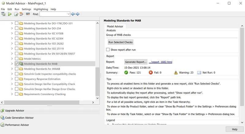 Model-in-the-loop (MIL) simulation or model-based testing First, you need to extend the actual system (hardware) version in a simulation environment that includes Simulink, which maximizes the critical functionality of your hardware system. Once the system version is created, expand the control version to see if the control can manage the system (in this case the motor version) according to your requirements. This step is called Model-in-Loop (MIL) and confirms the common sense of the controller in the simulated version of the plant. If the controller is functioning as expected, you should report the controller's inputs and outputs for later verification levels.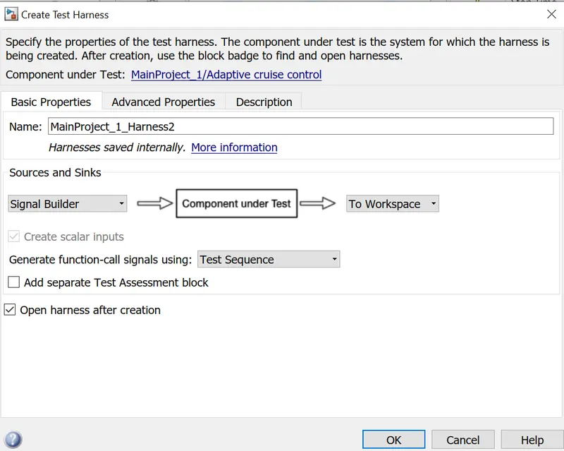
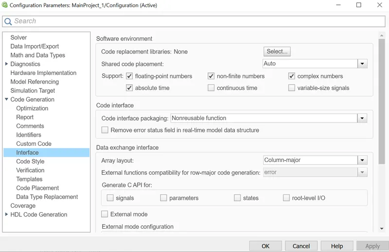
ENABLING OF "SUPPORT FLOATING NUMBERS"
Specify whether to generate floating-point data and operations.
Category: Code Generation > Interface
conditions for enabling
-
This option only appears if the file is ERT-based targets.
-
It requires Embedded Coder® license when generating code.
-
Selecting this parameter enables Support: non-finite numbers and disabling this parameter disables Support: non-finite numbers.
-
It must be the same for top-level and referenced models.
-
When you select parameter MAT-File Logging, you must also select Support: non-finite numbers and Support: floating-point numbers.
DOCUMENTATION TAGGING TO SIMULINK SUBSYSTEM
- Make a word file that needs to be tagged and save it in the same folder as the Simulink file.
- Select the text that has the same content and description for the subsystem block.
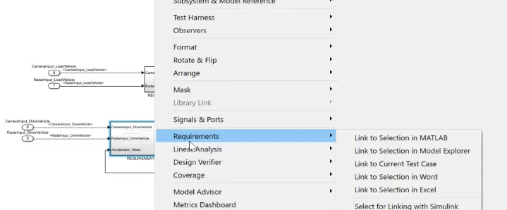
- Right-click on the subsystem block go to requirement click on the link to selection in word