Project 1- Traffic Jam Assistant Feature
Traffic Jam Assistant Feature
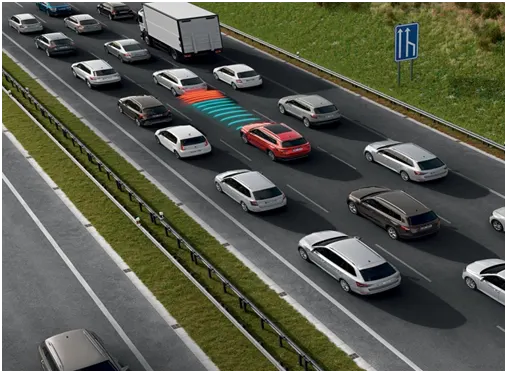
Today, more and more automobiles are equipped with Traffic Jam Assist, which is designed to make driving in traffic more comfortable. Traffic Jam Assist is an extension of Adaptive Cruise Control. When you approach traffic the speed of the vehicle slow down to make sure it reaches without much stopping. When you approach traffic the speed of the vehicle slow down to make sure it reaches without much stopping. You can take your foot off the pedals when the system is turned on. Traffic Jam Assist automatically slows and accelerates your vehicle while keeping a safe distance from the vehicle in front of you. This is simply a low-speed adaptation of Adaptive Cruise Control.
The technology measures the distance to the car ahead using a specific radar sensor and adjusts the speed to ensure it does not exceed the predetermined value. Furthermore, adaptive cruise control keeps a constant distance to the vehicle ahead of you. The driver can select one of four distance programmes (model dependent), altering the system's dynamics to meet his or her needs: Distance 1 (sporty), Distance 2 and 3 (standard), and Distance 4 (long) (comfortable). Even when adaptive cruise control is turned on, the driver is still in charge of monitoring the car's speed and distance from the vehicle in front. The adaptive cruise control does not react to stationary or approaching objects.
Traffic Jam Assistant is one of the most common feature in Advanced Driver Assistance System. Traffic Jam Assistant helps the driver arrive more relaxed at their destination, even in dense traffic or in traffic jams. As a partially automated comfort function, the system takes over the longitudinal & lateral guidance of the vehicle. This means that the car can drive off, accelerate & brake automatically, as well as steer the vehicle within certain constraints. The driver has to permanently supervise the system & be ready to take over the complete control of the vehicle at any time.
Traffic Jam Assistant system helps to avoid rear end collisions in dense traffic conditions & traffic jams. In Traffic jams, the vehicle takes over driving off, acceleration, braking and steering within same lane.
Basic Working Principle:
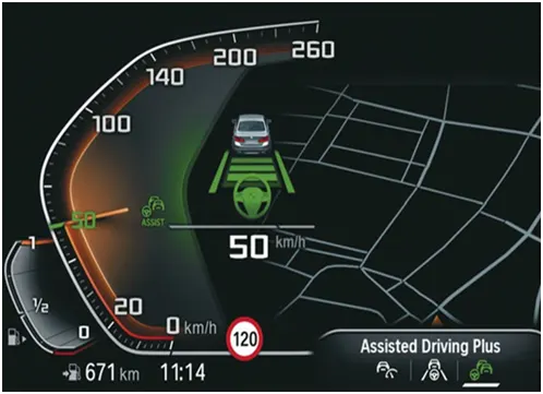
Traffic Jam Assistant is based on the sensors and the functionality of the Adaptive Cruise Control (ACC) with stop & go and Lane Keeping Support (LKS). When ACC ‘Stop & Go’ is turned ON, the Traffic Jam Assistant continuously analyses the speed of the surrounding vehicles and compares it with the own driving speed. If the system detects dense traffic or a traffic jam at speeds less than 60 kmph, the driver can activate the functionality by press of a button. The vehicle will now automatically follow the vehicle in front, takes over driving off, acceleration, braking and steering within same lane.
Information regarding the Traffic Jam Assistant will be available to be displayed to the driver in the Instrument Panel Cluster (IPC). The Algorithm which the students need to implement here in this project is predominantly based on IPC units.
Problem Statement:
To develop one specific requirement of Traffic Jam Assistant algorithm which would predominantly feature in the IPC algorithm.Please note that the whole Traffic Jam Assistant is a very huge algorithm & only one small part of the logic is implemented here. Idea is to familiarize with concepts of Model Based Development in MATLAB Environment. The Project must be done keeping in mind the following processes & steps.
- This model must be developed in MATLAB Simulink as per MBD guidelines.
- Code Generation Profile must be in Embedded Coder.
- Simulink Data Dictionary must be created for the model & must be linked to the model.
- Model Advisor Report is mandatory & this will be followed by Code Generation.
Input Signals:
|
Name of the Signal |
Data Type |
Range |
|
Input_Voltage |
uint8 |
0 - 255 |
|
Input_Switch |
boolean |
0 – 1 |
|
Enable_Display |
uint8 |
0 - 255 |
Output Signal:
|
Name of the Signal |
Data Type |
Range |
|
Output_Display |
uint8 |
0 - 255 |
Calibration Signals:
|
Name of the Signal |
Data Type |
Range |
Initial Value |
|
VOLTAGE_MINIMUM_RANGE |
uint8 |
0 – 255 |
30 |
|
VOLTAGE_MAXIMUM_RANGE |
uint8 |
0 – 255 |
50 |
|
OFF_MODE |
uint8 |
0 – 255 |
2 |
|
ON_MODE |
uint8 |
0 – 255 |
1 |
|
STANDBY_MODE |
uint8 |
0 – 255 |
3 |
|
INTERRUPT_1 |
boolean |
0 – 1 |
1 |
|
INTERRUPT_2 |
boolean |
0 - 1 |
1 |
|
NO_DISPLAY |
uint8 |
0 – 255 |
0 |
Local Signal:
|
Name of the Signal |
Data Type |
Range |
|
Optimum_Voltage |
boolean |
0 - 1 |
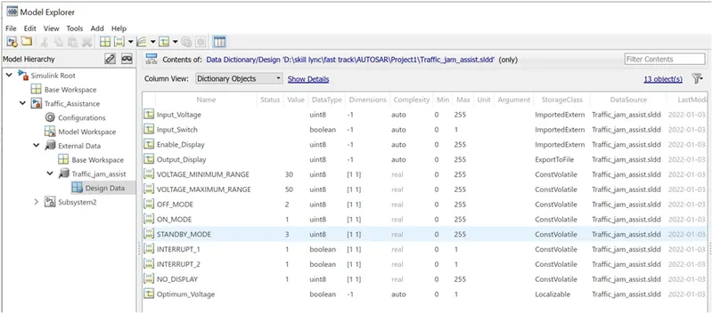
Simulink Data Dictionary(SLDD): MathWorks introduced a new feature in 2014 that is called Simulink Data Dictionary. This new feature provides the ability to save data types, parameters, and signals to database files. This is good news for embedded developers who need flexibility in using data objects and don't want to use the default workspace, which can lead to data corruption. In the initial implementation, the data dictionary interface is provided by the Simulink Model Explorer. The GUI is clean, intuitive, and easy to use. It helps in importing and exporting dictionaries to m-files and mat-files.
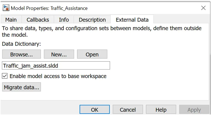
The Simulink data dictionary, also known as SLDD, exists as a file with the standard file extension .sldd. The dictionary file can be opened with the open function that calls opensldd. This will open the file and launch Simulink Model Explorer on the selected dictionary node. Opening the dictionary creates a cached copy. Manipulating the dictionary modifies the cached copy. The dictionary file changes only if the changes are saved with the appropriate command. You can add elements to the dictionary by creating a model, default workspace, or new element in the Model Explorer. You can pre-link a Simulink model using the Model Properties drop-down menu in the Simulink Editor. Data dictionaries allow you to customize model code generation for a variety of purposes by simply changing the dictionary you are using.
The process of making SLDD file for the model
Go to Model properties > click on the external Data>create a new file with .sldd extension> save the file
Add Simulink signal for adding input, output and local signals and using simulink parameter for adding constant data.
-give the value for maximum and minimum along with the data type if required change resolution as asked.
The process of linking SLDD file with the model
Go to Modeling > Model Setting > Model Properties > External Data > Browse
Model for Traffic Jam Assistance
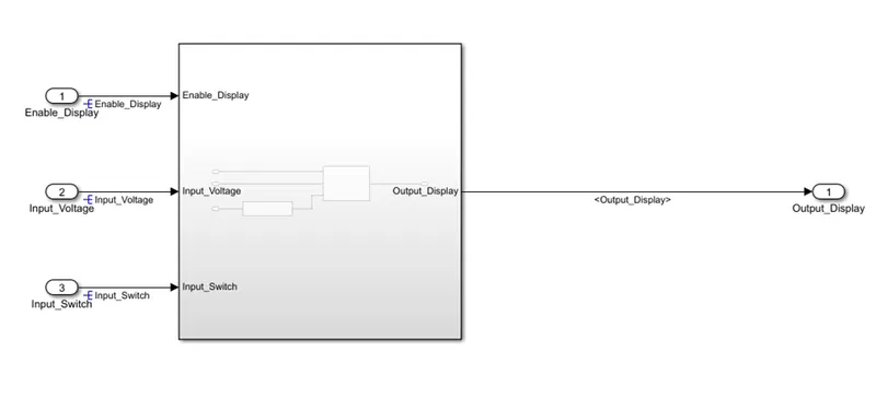
Requirement No 1:
- Input Signal “Input_Voltage” is compared against voltage values “VOLTAGE_MINIMUM_RANGE” & “VOLTAGE_MAXIMUM_RANGE”.
- Incoming input signal “Input_Voltage” must be greater than – equal to “VOLTAGE_MINIMUM_RANGE” and less than – equal to “VOLTAGE_MAXIMUM_RANGE”.
- Output signal from here is “Optimum_Voltage” which will be one of the inputs to the subsystem “DisplayUnit”.
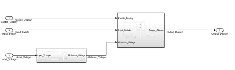
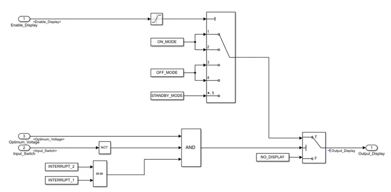
Requirement No 2 (DisplayUnit Subsystem):
- Input Signals are “Optimum_Voltage”, “Input_Switch”, “Enable_Display”. Signal “Enable_Display” must be saturated between the range 0 – 7. Output signal from the subsystem is “Output_Display”.
- Input Signal “Enable_Display” is compared against pre-defined set of values in a multiport switch. Total data ports in the multiport switch is 5.
- Multiport switch inputs 1 & 2 is connected to calibration signal “ON_MODE”, Multiport switch inputs 3 & 4 is connected to calibration signal “OFF_MODE” while Multiport switch input 5 is connected to calibration signal “STANDBY_MODE”.
- The output from Multiport switch is connected to the first input port of the Switch block. The third input port of the Switch block is connected to the calibration signal “NO_DISPLAY”.
- Meanwhile NOT value of input signal “Input_Switch” is compared in an AND gate against input signal “Optimum_Voltage” and the output from comparing if calibration signals “INTERRUPT_1” & “INTERRUPT_2” are equal. The output of the AND gate is the second input of the switch block.
- The output from the switch block is “Output_Display”.
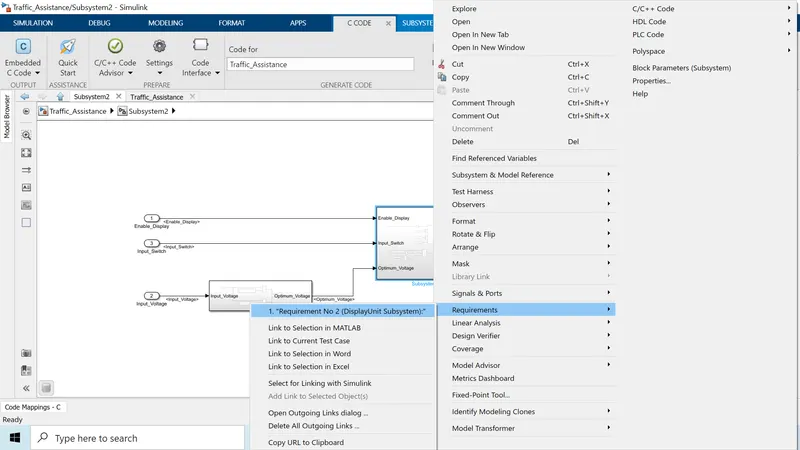
Steps to the attached requirement for the subsystems
- For attaching the document to the model first the document should be saved in the same folder as Simulink file.
- Select the text where requirement information for the subsystem is there go to the subsystem right click on it from requirement link to the word
Model Advisor Report for MAB guidelines
The Model Advisor tests the version or subsystem to see the modeling situation and configuration settings that make the simulation of the machine that the version represents incorrect or inefficient. Model Advisor testing helps ensure compliance with business requirements and tips. Model Advisors allow initiatives and improvement teams to enable certain modeling tips. Once the version has been evaluated, the Model Advisor will create a document that lists the suboptimal situations, settings, and modeling strategies and suggests solutions as needed.
You can use the Model Advisor to test the version in the following ways:
- Model AdvisorPerform Tests Interactively Configure Model Advisor to run turnaround time tests mechanically (call Simulink ® Check ™)
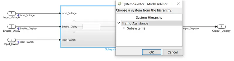
Go to task and select MAB guideline and run to get model advisor report.
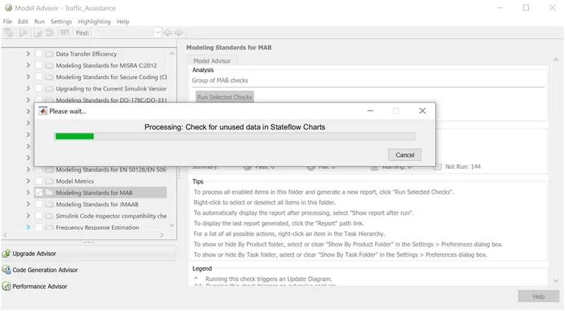
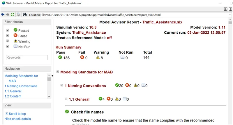
Model Advisor Report
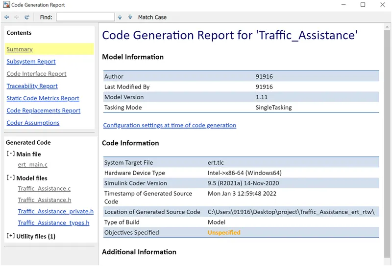
Code generation report:
To make a Code Generation Report.
- When the model is completed, the following code generation report is generated: Select Report Options from the Open Report list on the C Code tab. When you open the Configuration Parameters dialogue box, the Code Generation > Report pane is available.
- Choose the parameter Create code creation report.
- Select the Open report automatically parameter if you want the code generating report to open automatically after you generate code (which is enabled by selecting Create code generation report).
- Generate code.
Code generated:
File: Traffic_Assistance.c
1	/*
2	 * File: Traffic_Assistance.c
3	 *
4	 * Code generated for Simulink model 'Traffic_Assistance'.
5	 *
6	 * Model version                  : 1.11
7	 * Simulink Coder version         : 9.5 (R2021a) 14-Nov-2020
8	 * C/C++ source code generated on : Mon Jan  3 12:59:48 2022
9	 *
10	 * Target selection: ert.tlc
11	 * Embedded hardware selection: Intel->x86-64 (Windows64)
12	 * Code generation objectives: Unspecified
13	 * Validation result: Not run
14	 */
15
16	#include "Traffic_Assistance.h"
17	#include "Traffic_Assistance_private.h"
18
19	/* Exported data definition */
20
21	/* Definition for custom storage class: ExportToFile */
22	uint8_T Output_Display;                /* '<S3>/Switch' */
23
24	/* ConstVolatile memory section */
25	/* Definition for custom storage class: ConstVolatile */
26	const volatile boolean_T INTERRUPT_1 = 1;/* Referenced by: '<S3>/Constant4' */
27	const volatile boolean_T INTERRUPT_2 = 1;/* Referenced by: '<S3>/Constant5' */
28	const volatile uint8_T NO_DISPLAY = 1U;/* Referenced by: '<S3>/Constant3' */
29	const volatile uint8_T OFF_MODE = 2U;  /* Referenced by: '<S3>/Constant1' */
30	const volatile uint8_T ON_MODE = 1U;   /* Referenced by: '<S3>/Constant2' */
31	const volatile uint8_T STANDBY_MODE = 3U;/* Referenced by: '<S3>/Constant' */
32	const volatile uint8_T VOLTAGE_MAXIMUM_RANGE = 50U;/* Referenced by: '<S2>/Constant' */
33	const volatile uint8_T VOLTAGE_MINIMUM_RANGE = 30U;/* Referenced by: '<S2>/Constant1' */
34
35	/* Real-time model */
36	static RT_MODEL_Traffic_Assistance_T Traffic_Assistance_M_;
37	RT_MODEL_Traffic_Assistance_T *const Traffic_Assistance_M =
38	  &Traffic_Assistance_M_;
39
40	/* Model step function */
41	void Traffic_Assistance_step(void)
42	{
43	  /* local block i/o variables */
44	  boolean_T Optimum_Voltage;
45	  uint8_T tmp;
46
47	  /* Logic: '<S2>/Logical Operator' incorporates:
48	   *  Constant: '<S2>/Constant'
49	   *  Constant: '<S2>/Constant1'
50	   *  Inport: '<Root>/Input_Voltage'
51	   *  RelationalOperator: '<S2>/Relational Operator'
52	   *  RelationalOperator: '<S2>/Relational Operator1'
53	   */
54	  Optimum_Voltage = ((Input_Voltage >= VOLTAGE_MINIMUM_RANGE) && (Input_Voltage <=
55	    VOLTAGE_MAXIMUM_RANGE));
56
57	  /* Switch: '<S3>/Switch' incorporates:
58	   *  Constant: '<S3>/Constant4'
59	   *  Constant: '<S3>/Constant5'
60	   *  Inport: '<Root>/Input_Switch'
61	   *  Logic: '<S3>/Logical Operator'
62	   *  Logic: '<S3>/Logical Operator1'
63	   *  RelationalOperator: '<S3>/Relational Operator'
64	   */
65	  if (Optimum_Voltage && (!Input_Switch) && (INTERRUPT_2 == INTERRUPT_1)) {
66	    /* Saturate: '<S3>/Saturation' incorporates:
67	     *  Inport: '<Root>/Enable_Display'
68	     */
69	    if (Enable_Display < 1) {
70	      tmp = 0U;
71	    } else {
72	      tmp = 1U;
73	    }
74
75	    /* End of Saturate: '<S3>/Saturation' */
76
77	    /* MultiPortSwitch: '<S3>/Multiport Switch' */
78	    if (tmp == 1) {
79	      /* Switch: '<S3>/Switch' incorporates:
80	       *  Constant: '<S3>/Constant2'
81	       */
82	      Output_Display = ON_MODE;
83	    } else {
84	      /* Switch: '<S3>/Switch' incorporates:
85	       *  Constant: '<S3>/Constant'
86	       */
87	      Output_Display = STANDBY_MODE;
88	    }
89
90	    /* End of MultiPortSwitch: '<S3>/Multiport Switch' */
91	  } else {
92	    /* Switch: '<S3>/Switch' incorporates:
93	     *  Constant: '<S3>/Constant3'
94	     */
95	    Output_Display = NO_DISPLAY;
96	  }
97
98	  /* End of Switch: '<S3>/Switch' */
99	}
100
101	/* Model initialize function */
102	void Traffic_Assistance_initialize(void)
103	{
104	  /* (no initialization code required) */
105	}
106
107	/* Model terminate function */
108	void Traffic_Assistance_terminate(void)
109	{
110	  /* (no terminate code required) */
111	}
112
113	/*
114	 * File trailer for generated code.
115	 *
116	 * [EOF]
117	 */
118
Conclusion:
- The model is developed in MATLAB Simulink for implementing a specific portion of ‘Traffic Jam Assistant’ feature as per Model Based Design (MBD) guidelines.
- Simulink Data Dictionary is created for the model and is linked to the model.
- Model Advisor Report is checked, followed by code generation using embedded coder for the developed model.