Project
Aim: To study and prepare a detailed report on the BAJA ATV model explaining the model properties and comments on the results taken after performing the simulation of BAJA ATV.
Objective: Prepare a report explaining the model properties of different modes and comment on their results.
Theory: All-Terrain Vehicles (ATVs) are among the most practical land vehicles ever devised. They are designed to tackle the risks of many types of terrain and can be utilized on almost any worksite. They not only make driving easier, but they are also safe to utilize when moving loads or goods.
While ATVs make excursions safer, they are not without risks. In fact, over 800,000 accidents have been connected to this sort of vehicle in the last ten years. On-site mobility, dangerous machines, and loss of control are examples of such mishaps.
- All train vehicles (ATVs) also known as light utility vehicles {LUV] are vehicles that travel on low-pressure tires.
BAJA SAE
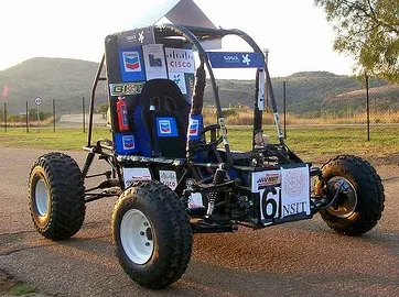
The BAJA SAE Series is a global event conducted by the Society of Automotive Engineers, the USA for undergraduate engineering students. In 1976, at the University of Carolina, the event was known as Mini - BAJA. Since then, the event has taken place in six countries: the United States, Mexico, South Africa, Korea, Brazil, and India
- In a society of automobile engineers international(SAE international). Students from universities all over the world design and build small ATVs off-road cars with engine having same specifications
- The BAJA SAE challenges students to design, fabricate, and validate a single-seater four-wheeled off-road vehicle to participate in a series of events over the course of five days that test the vehicle for the sound engineering practices that went into it, the agility of the vehicle in terms of gradability, speed, acceleration, and maneuverability characteristics.
- All vehicles must pass a technical check before being allowed to operate under power during technical evaluations. During the event, officials may inspect the car at any time. It is divided into three stages: electrical inspection, safety scrutiny, and panic braking.
CVT: CVT is an automatic gearbox since the driver does not have to manually change between forwarding gears or operate a clutch pedal. However, there are significant changes in both form and function between the two.
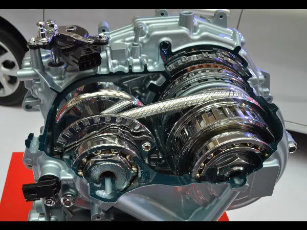
- A CVT, unlike a typical automatic (or manual transmission), does not have a fixed number of preset ratios. Instead, it employs an infinite number of gear ratios to match the driver's style and the driving conditions at any particular time. A CVT transmission is commonly referred to as "single-speed" or "shiftless" since it enables for seamless shifts without any hard shift points.
- A CVT achieves this unlimited gear ratio flexibility by utilizing two opposed cone-shaped pulleys connected by a chain or belt. This arrangement is quite similar to how a chain moves across the gears of a bicycle.
- The engine output shaft is attached to one cone, while the driveshaft and drive wheels are connected to the other. The gear ratio changes as the pulleys move closer and further apart, forcing the chain or belt to move up and down the sides of the two cones. This action changes the diameter of the chain or belt, which changes the gear ratio based on the amount of power required. As the car moves, these real-time adjustments occur continuously
Blocks used in BAJA ATV model simulation and their purpose:
- Signal builder: It is used to create a signal as given in the data or by applying the required piecewise linear signal.
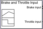
- Goto: This block passes its input to its corresponding from the block. it can take real, complex and vector value data it sends data to from block without any physical connection.

- Simulink-PS converter: It converts Simulink signals into physical signals.

- Solver Configuration: It specifies the solver parameter that your model needs before the simulation begins.

- Generic Engine: It represents the sublevel model of spark-ignition and diesel engine suitable for use at the initial stage of modeling.
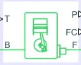
- Simple gear: The simple gear block represent a gearbox that connects driveline axes of the base gear B and the next gear F to corotate with a fixed ratio you assign.

- Ideal rotational motion sensor: It is the device that converts a differences variable measured between two mechanical rotational nodes into a more controlled signal proportional to angular R and C are rotational conserving ports that connect the block to nodes where motion is being monitored.

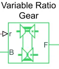
- Variable Ratio gear: It represents a gearbox that represents dynamically transfer motion and torque between two connected drive shaft.
- Inertia block: It represents mechanical translational inertia.

- Double shoe break: It represents a frictional brake with two pivoted rigid shows which is pressed against a rotating drum to produce braking action. F is a physical input port and S is a rotational port with a drum shaft.

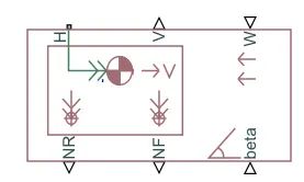
- Vehicle body: It represents a two-axle vehicle body in longitudinal motion. it can have the sum of different numbers of wheels on each side h is horizontal motion. V is the longitudinal velocity in m/s. W is a headwind speed in m/s. β is road inclination.
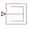
- Ps terminator: it terminates physical signal constant.
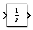
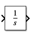
- Integrator: This block integrates the input value with respect to time.
- Scope: Display output by designing graph.
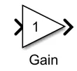
- Gain: Element is used to make a gain(y=K*u) in the mathematical equation in the matrix.
 MODEL 1: BAJA ATV with CVT without the dashboard
Case 1: When brakes and throttle is given by signal builder using data loader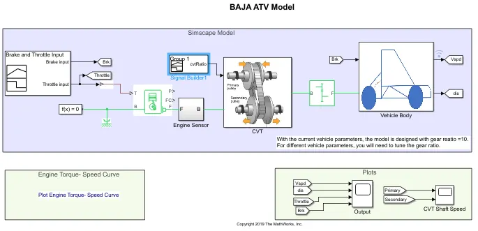
Model Input:
- The variables m1,m2 are the mass input at input and output shaft for the CVT transmission system.
- The variable speed and torque vectors are the input parameter for the generic engine which give us the relation between torque and RPM of the engine.
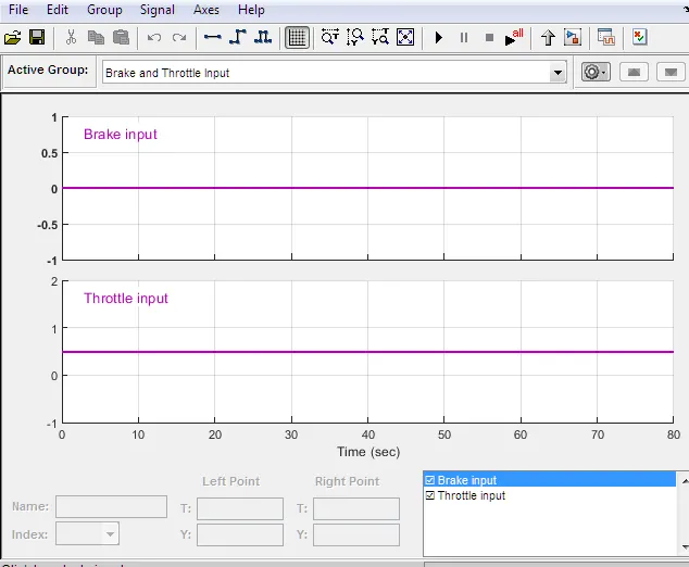
- As we don't have a dashboard the brake and throttle are given using Signal builder and its ratio is changed with respect to time.
Working:
- The model consists of a generic engine, CVT, vehicle body, engine sensor, simple gear, signal builder, and scope.
- Using variable speed vector and torque vector the signal from the signal builder is given to the generic engine at the point T.
- Point B is connected to solver configuration with a mechanical rotational reference block for finding the solution.
- The output of the generic engine is then passed through the engine sensor block at point F where it records the RPM of the engine.
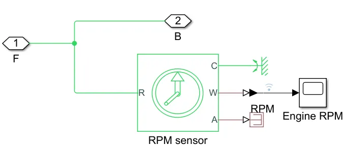
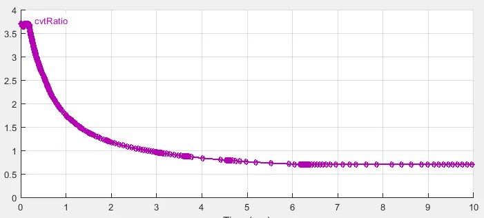
- The recorded value is given to the CVT Transmission block where it takes two inputs one from a signal builder and one from the engine sensor block at point B, the values provide the CVT ratio.
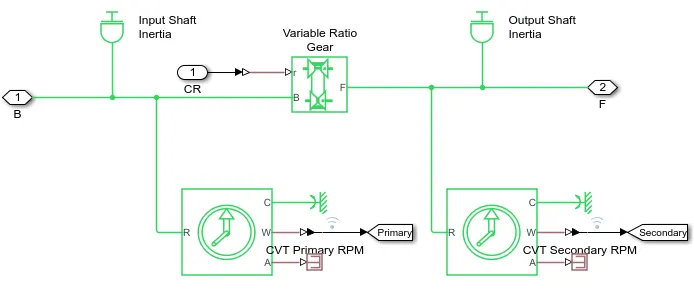
- CVT subsystem consists of the ideal rotational motion sensor for primary and secondary RPM, Two inertia blocks for Input and output shafts, Variable Ratio Gear
- The vehicle body block has two inputs one from the engine from the simple gearbox and another from the brake input.
- This model is for TWD(two-wheel drive) vehicles. the input engine signal is provided to both rear wheels from the simple gear.
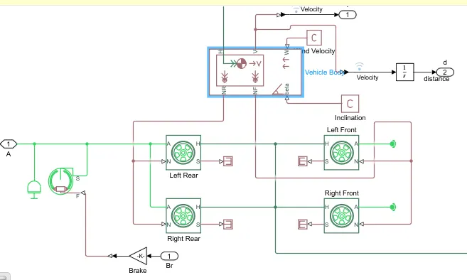
- Since there is the rotational inertia of the shaft so it is connected to the engine input signal before it reaches the tire.
- The input brake is provided to double shoe brake block which is passed through the gain block that intensifies brake input.
- As brakes are indirectly connected to the input power of the wheel, the output of the double shoe brake is connected to the input of the engine before it reaches the tires.
- Mass is given as 250 kg and CG distance 1m and 0.5m to front and rear axle respectively, another vehicle block inside vehicle body defines body mass, weight distribution between axle due to acceleration, aerodynamics drag due to this data the force on tires are distributed accordingly.
- The output from the vehicle body gives velocity and the signal is then passed through the integrator to get the distance covered.
- The output data from the scope is engine RPM for a primary and secondary CVT transmission and the other has a throttle, distance, velocity, and brake value of the vehicle.
Output:
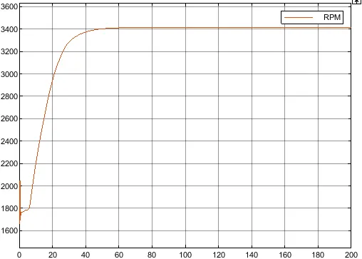
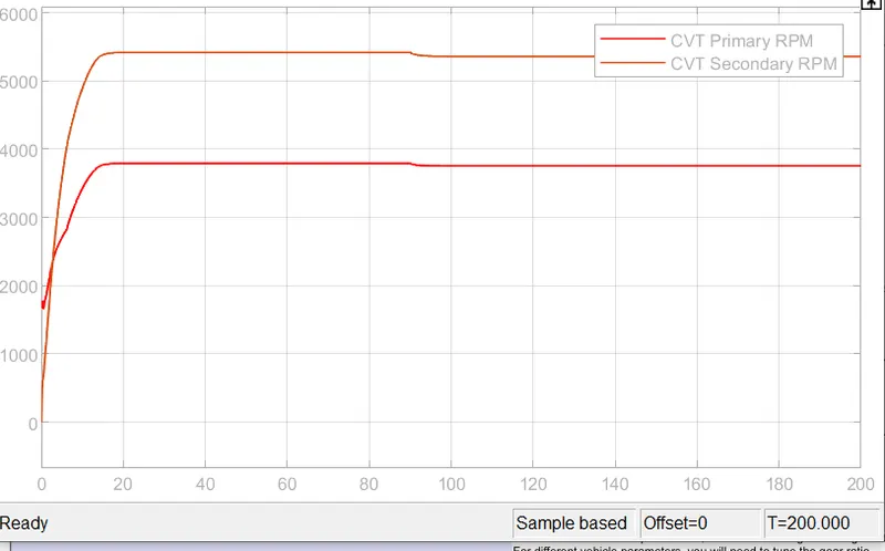
Engine RPM: Initial velocity of the engine is 1750 rpm, then as we keep the constant input i.e throttle value is constant, after a certain time the rpm of the engine also becomes constant.
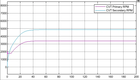
Primary shaft rpm: It looks similar to engine rpm because the primary shaft is connected to the engine but due to inertia and other factors it will have losses due to which secondary shaft speed is achieved by CVT ratio.
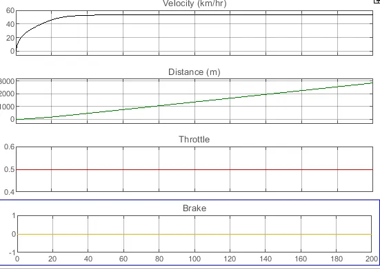
Vehicle output:
- The throttle valve, brake value, velocity, and distance are displayed on the scope.
- The throttle and brake value are constant during complete simulation, while initially velocity increases rapidly and then after a certain point it becomes constant.
distance is calculated by integrating velocity.
Model 2 : BAJA ATV model with dashboard
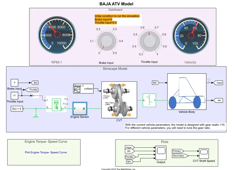
Case 1: When brakes and throttle is given by dashboard while the model is a simulation is running and the output is noted
- Signal builder: It is used to create a signal as given in the data or by applying the required piecewise linear signal.
- Goto: This block passes its input to its corresponding from the block. it can take real, complex and vector value data it sends data to from block without any physical connection.
- Simulink-PS converter: It converts Simulink signals into physical signals.
- Solver Configuration: It specifies the solver parameter that your model needs before the simulation begins.
- Generic Engine: It represents the sublevel model of spark-ignition and diesel engine suitable for use at the initial stage of modeling.
- Simple gear: The simple gear block represent a gearbox that connects driveline axes of the base gear B and the next gear F to corotate with the fixed ratio you assign.
Ideal rotational motion sensor: It is the device that converts a differences variable measured between two mechanical rotational nodes into a more controlled signal proportional to angular R and C are rotational conserving ports that connect the block to nodes where motion is being monitored.
- Variable Ratio gear: It represents a gearbox that represents dynamically transfer motion and torque between two connected drive shaft.
- Inertia block: It represents mechanical translational inertia.
- Double shoe break: It represents a frictional brake with two pivoted rigid shows which are pressed against a rotating drum to produce braking action. F is a physical input port and S is a rotational port with a drum shaft.
- Vehicle body: It represents a two-axle vehicle body in longitudinal motion. it can have the same of a different number of wheels on each side h is horizontal motion. V is the longitudinal velocity in m/s. W is a headwind speed in m/s. β is road inclination.
- Ps terminator: it terminates physical signal constant.
- Integrator: This block integrates the input value for time.
- Scope: Display output by designing graph.
- Gain: Element is used to make a gain(y=K*u) in the mathematical equation in the matrix.
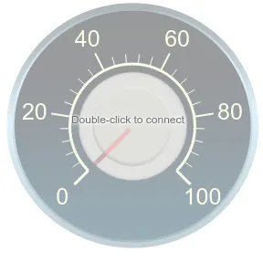
- Circular gauge: Display input on customized guage.
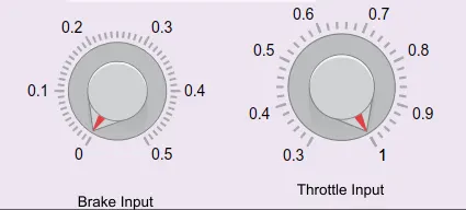
- Knob: Set a value to tune parameter variables.
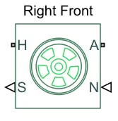
- Tire: Represent the longitudinal behavior of tyre on highways defined by Magic Formula
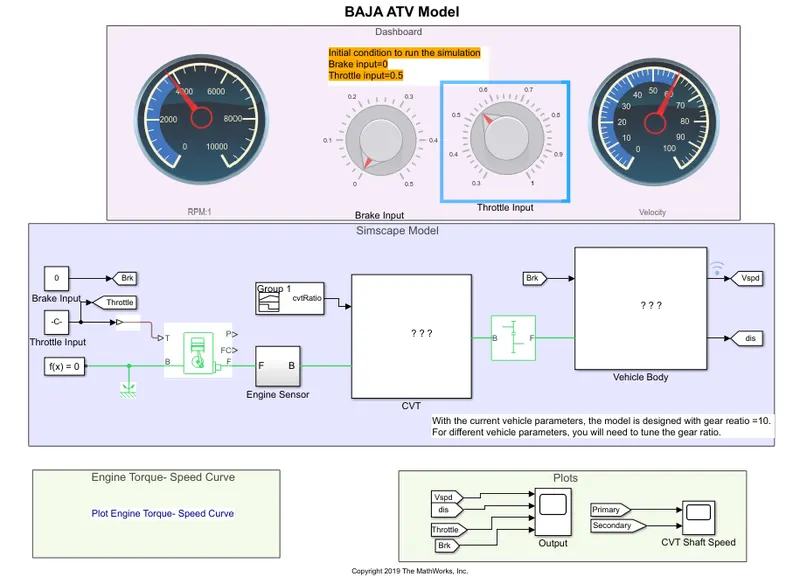
Model input:
- The variables m1,m2 stand for input masses at input and output shaft at CVT transmission.
- The variable speed and torque vectors are the input parameter for the generic engine which give us the relation between torque and RPM of the engine.
- As we have a dashboard the brake and throttle are given by using the knob.
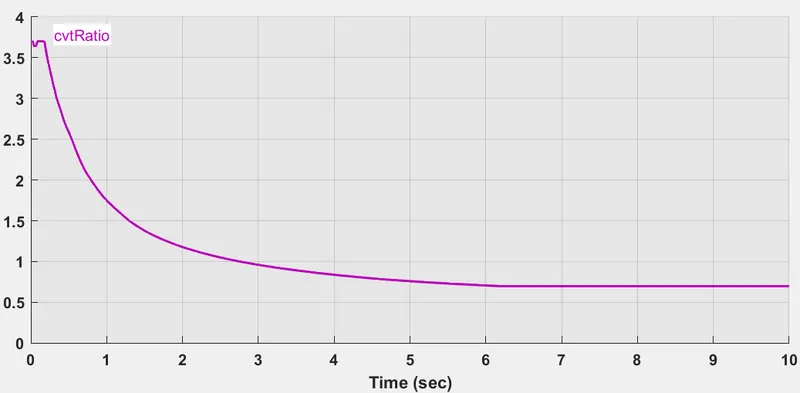
Using signal builder we can give CVT ratio
Working:
- The initial condition for the engine block is set according with engine parameters, the engine parameters are provided by using variables"speedvector and torquevector"
- The throttle and brake input is provided using graphical interface knob block which allow user to changer value while simulation is running.
- after receiving throttle and brake input engine block provide RPM, torque, and various factors depending on parameters.
- The output of the generic engine is then passed through the engine sensor block at point F where it records the RPM of the engine.
- The recorded value is given to the CVT Transmission block where it takes two inputs one from a signal builder and one from the engine sensor block at point B, the values provide the CVT ratio.
- CVT subsystem consists of the ideal rotational motion sensor for primary and secondary RPM, Two inertia blocks for Input and output shafts, Variable Ratio Gear
- This model is for TWD(two-wheel drive) vehicles. the input engine signal is provided to both rear wheels from the simple gear.
- The vehicle body block has two inputs one from the engine from the simple gearbox and another from the brake input.
- Since there is the rotational inertia of the shaft so it is connected to the engine input signal before it reaches the tire.
- The input brake is provided to double shoe brake block which is passed through the gain block that intensifies brake input.
- As brakes are indirectly connected to the input power of the wheel, the output of the double shoe brake is connected to the input of the engine before it reaches the tires.
- Mass is given as 250 kg and CG distance 1m and 0.5m to front and rear axle respectively, another vehicle block inside vehicle body defines body mass, weight distribution between axle due to acceleration, aerodynamics drag due to this data the force on tires are distributed accordingly.
- The output from the vehicle body gives velocity and the signal is then passed through the integrator to get the distance covered.
- The output data from the scope is engine RPM for a primary and secondary CVT transmission and the other has a throttle, distance, velocity, and brake value of the vehicle.
Output:
case 1: brake=0 &throttle=0.4
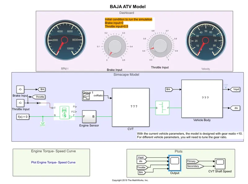
Output:
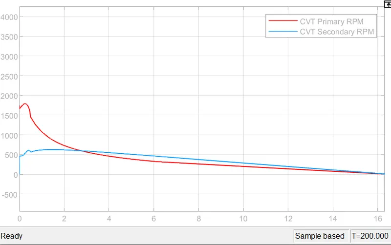
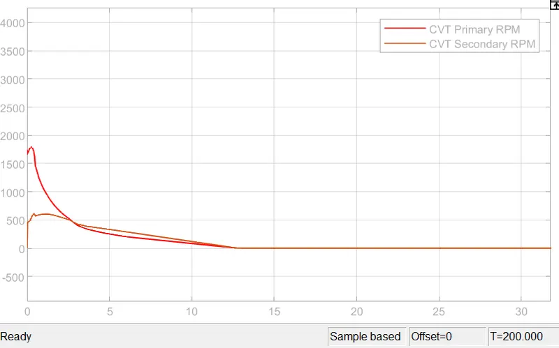
- Primary shaft is connected to engine and it look similar to engine RPM due to inertia and other factors.
- Hence primary shaft RPM will not be siimilar.
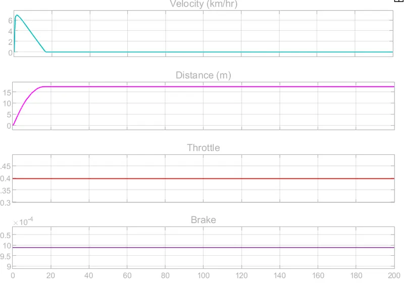
case 2: brake= varying, throttle=0.4
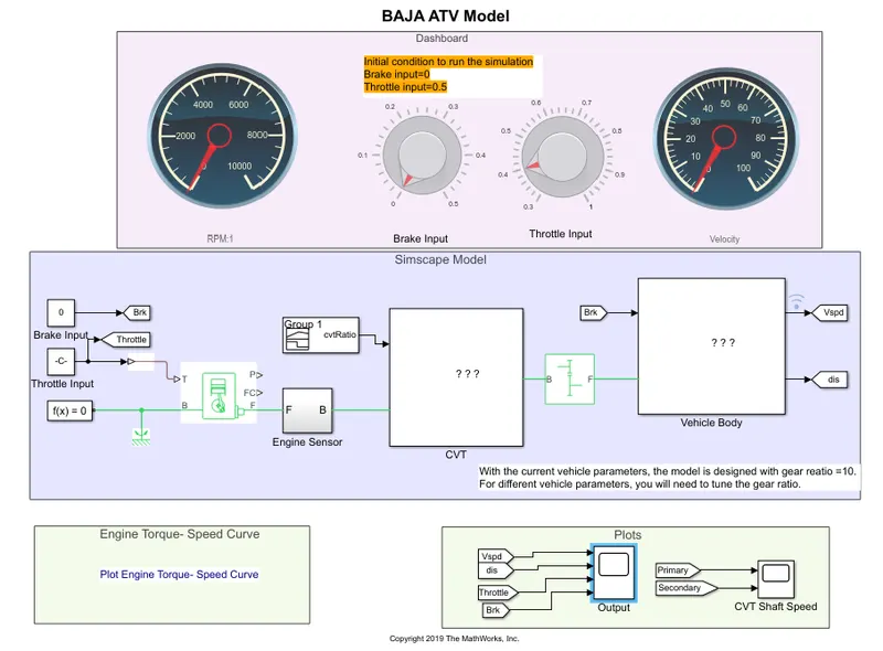
Output
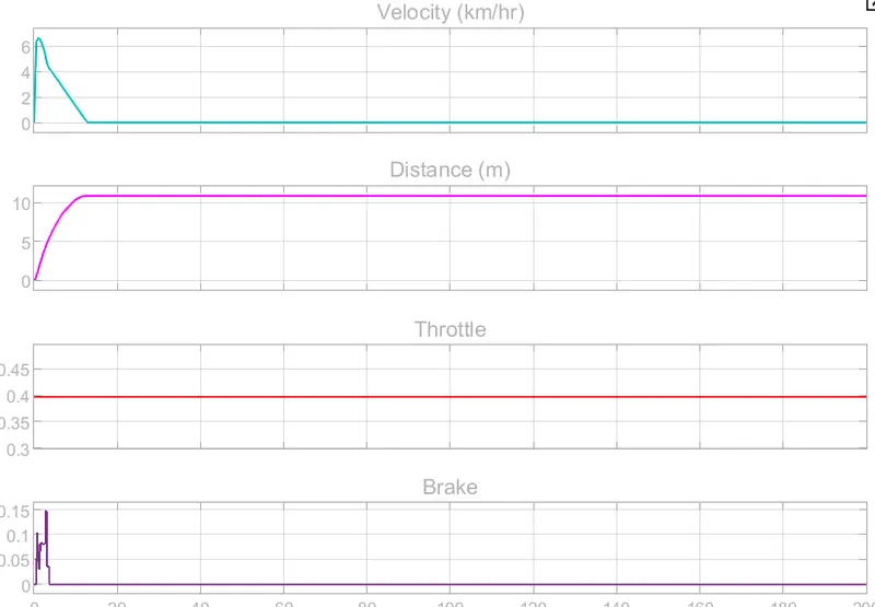
case 3: Brake=0 Throttle= Varying
output:
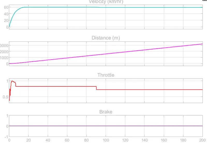
Conclusion:
- we can calculate time required to attain required speed or to stop vehicle.
- We can understand hoe vehicle may perform under different conditioin.
- we can calculate maximum speed vehicle can achieve.
- we can observe the performance of braking system and throttle system.