Week -2
Aim: To design a Simulink model of doorbell solenoid block using a DC source that closed the switch for two seconds and released it and observes the physical movement of the plunger.
Theory: Solenoid is the generic term for electromagnets that convert electrical energy to mechanical energy. It is electrical devices that work on the principle of electromagnetic effect moving a plunger towards a tone bar by passing an electric current through a coil which is wound. when the doorbell is pushed solenoid produces a magnetic field.
Requirement: Matlab
Project explanation: In this project, the solenoid is excited by supplying electric current with the help of a DC voltage source, the supply is controlled using a switch that is regulated by the pulse generator. In Simscape the block requires a solver configuration block for simulation. An ideal translational motion sensor is used to sense the movement in the plunger using the PS-Simulink converter they are observe using scope block. Both electrical reference and mechanical translation reference are used to connect translational port rigidly fixed to the ground.
SIMULINK MODEL OF DOORBELL USING SOLENOID BLOCK:
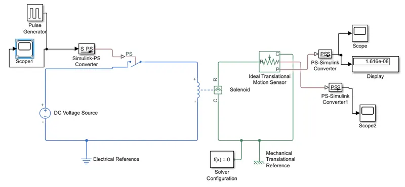
Simulation Block Explanation:
The pulse generator is used to generate square wave pulse with the reference time of two seconds switch on and two seconds off, the amplitude, pulse width, and phase delay determine the shape of output.

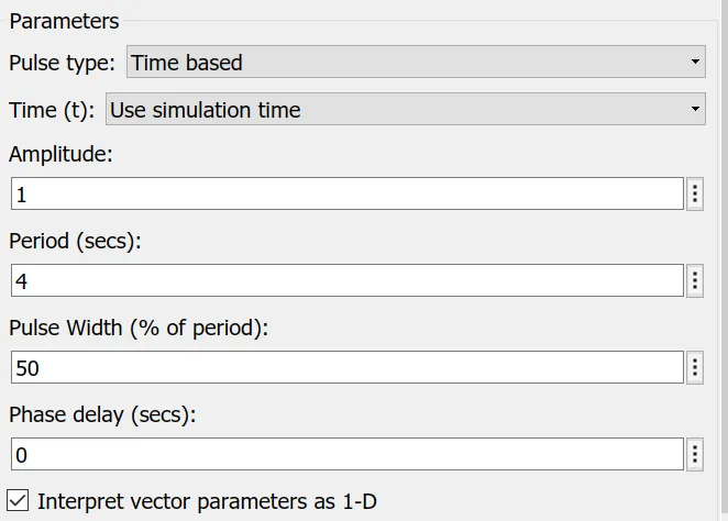
The pulse signals are plotted and converted to a real-time environment.
The switch act as a controller to the flow of current.
Scopes are connected to sensors to get the output.
PS-Simulink converters are used to convert the physical systems into Simulink signals.
Each physical system in Simscape is connected with a solver for simulation.
INPUT AS PULSE GENERATOR OF DC SOURCE
With the help of a pulse generator, the supply is regulated every 2 seconds and can be seen using a scope connected to the supply.
When the switch is closed the solenoid becomes an electromagnet and the plunger due to the magnetic force acting moves from port r to c hit the bell and produces sound.
OUTPUT VELOCITY:
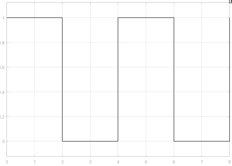
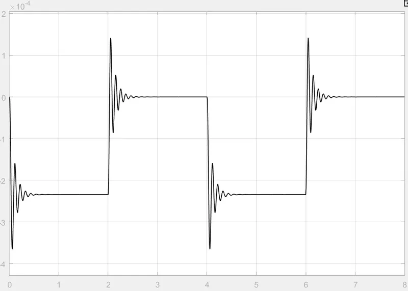
With the help of the scope attached to a motion sensor, it's understood that the bell rings every 2 sec in the time span of 8sec.
Hence we can observe the physical motion of the plunger by seeing the output signal on the scope from the transitional motion sensor
OUTPUT POSITION:
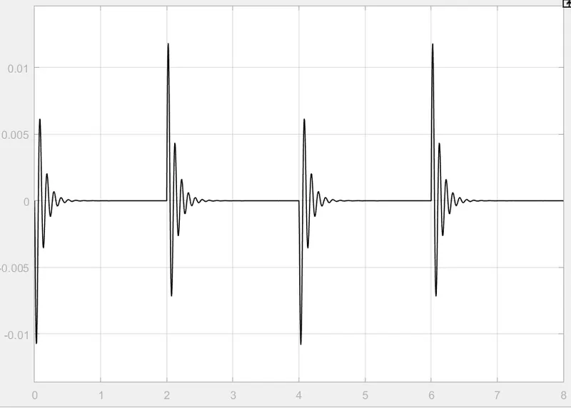
Using this solenoid parameter is set as port R moves towards port c, due to which a negative waveform is obtained.
CONCLUSION:
Using the appropriate block the solenoid function of converting electrical energy to mechanical energy is seen
The motion of the plunger is observed and recorded.
2)Aim: To study the thermistor behavior for various temperature conditions at different time intervals, And controlled the fan operation with respect to temperature.
Objective: Use a thermistor to sense the temperature of the heater & turn on or turn off the fan as per the below condition:
1) Temperature source:20°C from 0 to 10sec,27°C from 10 to 30 sec23°C from 30 to 50 sec.
2) Fan condition: On if the temperature is above 25 °C and off otherwise.
Theory:
Thermistor: It is a resistance thermometer or a resistor whose resistance depends on temperature.it is made up of metallic oxide, which is pressed into shapes like a bead, disk, or cylindrical shape and is then encapsulated with an impermeable material like glass and proxy.
They are two types of thermistor positive temp coefficient and negative temperature coefficient with positive temp coefficient temperature increases the resistance increases and the reverse happens for NTC
SIMULINK MODEL FOR THERMISTOR TO SENCE AND CONTROLLED FAN FOR COOLING:
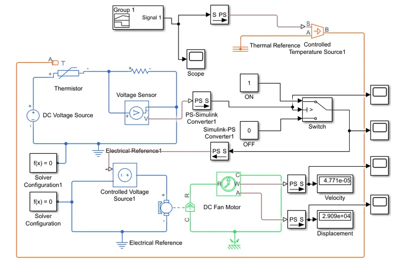
Block explanation:
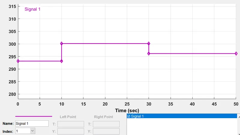
The Signal Builder block allows us to create linear input signals source as per the model need.it can quickly switch signals for facilitating testings. We can create the signal to get the desired output waveforms.
For this project the signal builder is designed in the manner it gives three input temperatures at different time intervals, the temperature is given in Kelvin as code requirement is in Kelvin.
Thermistor conditions:
1.20°C for (0-10 s)
- 27°C for (10-30 s)
- 23°C for (30-50 s)
2. Condition for FAN:
T=Above 25°C: ON
T=Below 25°C: OFF
 The output from the Controlled temperature source is given to the thermistor as an input. THermistor is a type of resistor whose resistance changes with respect to temperature. The temperature value is given in Kelvin(K).
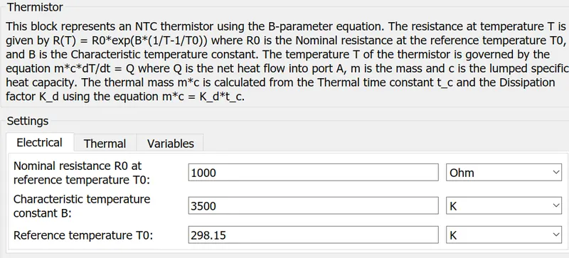
Voltage sensor block: To sense the voltage across resistance and check with the reference threshold temperature given in voltage form in the switch to operate.
Solver builder block: This is used to solve and simulate the physical system in Matlab Simscape.
Controlled voltage source block: To provide the controlled voltage to the electric motor.
PS and simulation block: Use to converter physical signal into simulation signal.
Scope block: It is used to observe the block.
Switch block: It is used to turn on and turn off a fan-controlled circuit with the reference threshold voltage.
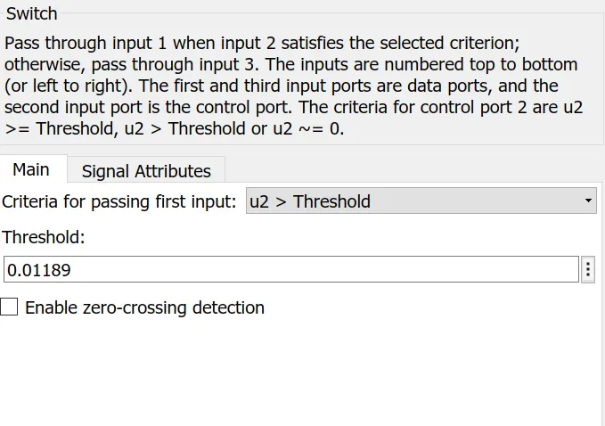
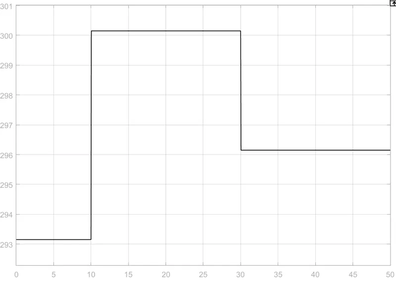
FOR THE ABOVE SYSTEM OUTPUT PLOTS ARE SHOWN.
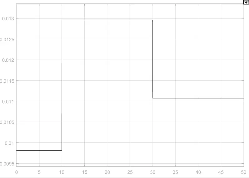
Voltage sensor output:
The output is shown for 27°C as it is above 25°C the output is given in voltage for 27°C as 0.1189.
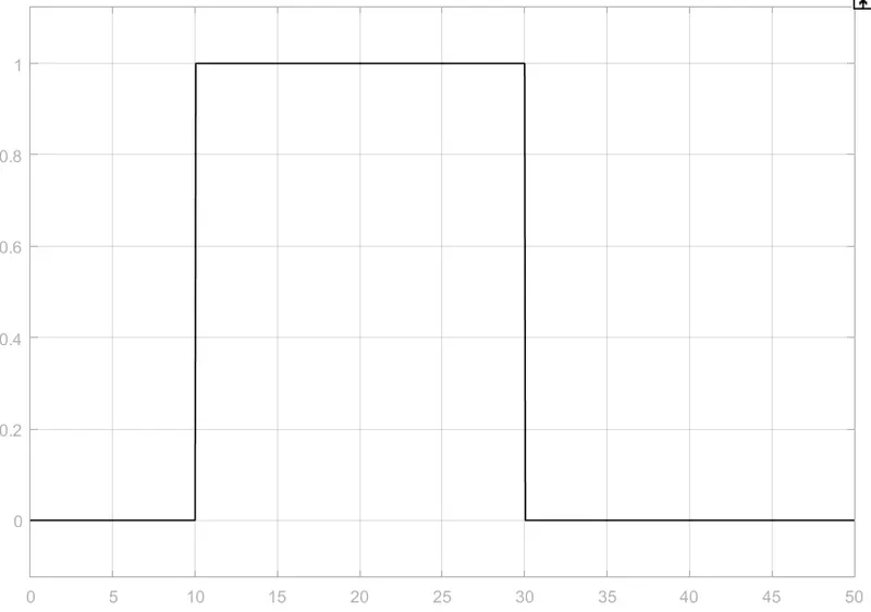
Switch output:
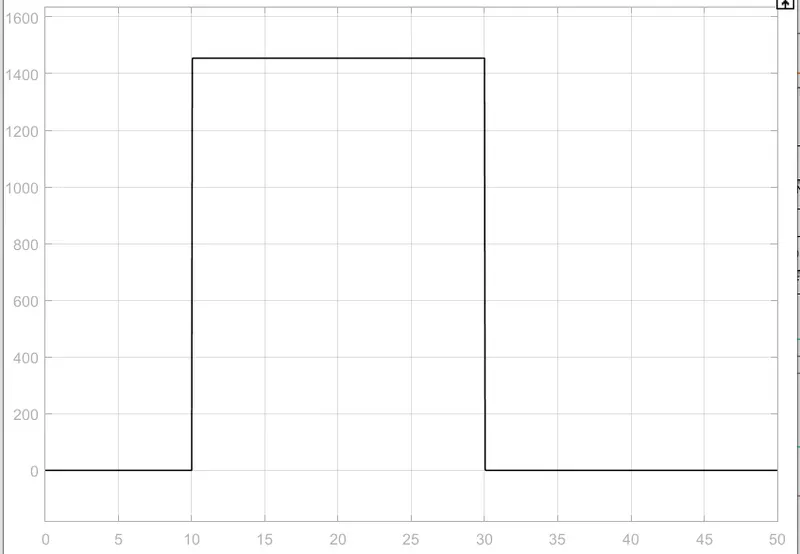
It will give out for (10-30) time interval as the temperature is above 25°C
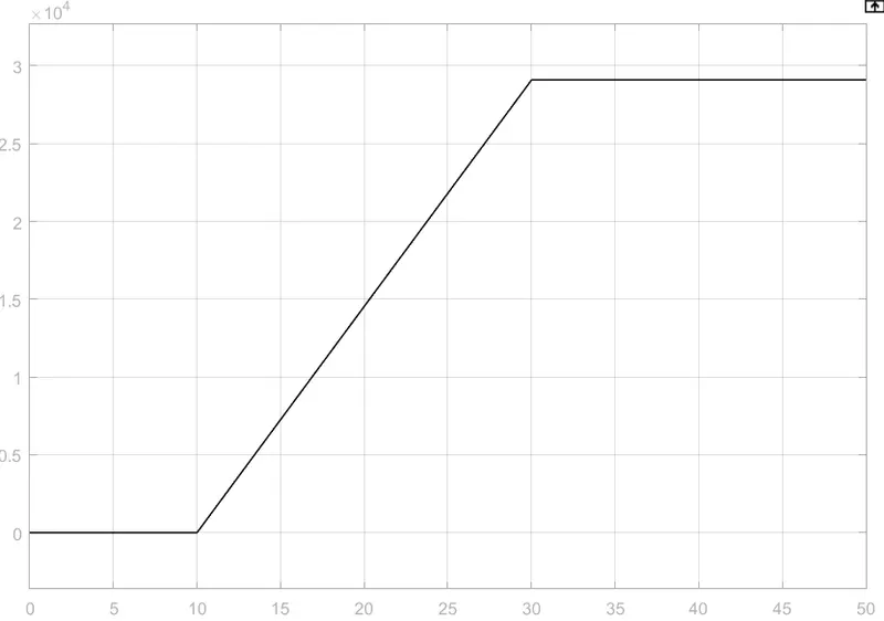
Output Velocity and Displacement Plots:
Conclusion: The control of the fan with respect to temperature is simulated using MatLab simulation. And also understanding the working of thermistors and their properties.