Week - 4
OBJECTIVE:
The main objective of this assignment is to accomplish the following tasks
- Create a control logic of washing machine using Stateflow
- Create a Simulink chart for the Gear shift logic
Washing Machine Model:
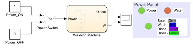
Fig.1: Simulink model - Washing Machine logic
This model shows a simple logic for working a washing machine. The Power supply is the main input and controls the entire model. The logic is split into different states using the state chart. The model was run for 500 secs and the results were found.
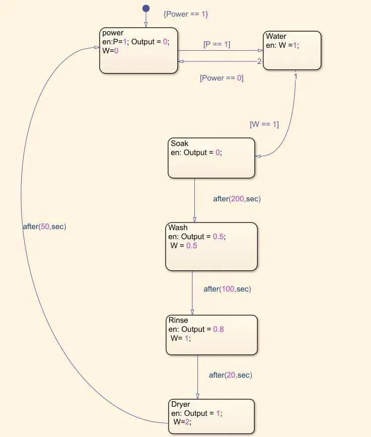
Fig.2: Flow for Washing logic
When the input enters the chart
- Water is also powered on and displays green LED on the Power panel
- Soak state gets activated and the output lamp is set to grey.
- After 200 secs, the wash state gets activated and the output displays blue color, and the water supply is reduced and can be visualized in scope.
- After 100 secs, the Rinse state gets activated and the output displays violet color and again the water supply is increased for rinsing purposes.
- After 20 secs, the Dryer state is activated and the water supply is turned off and the output lamp displays a green color.
- After 50 secs, the cycle gets repeated until the power supply is ON.
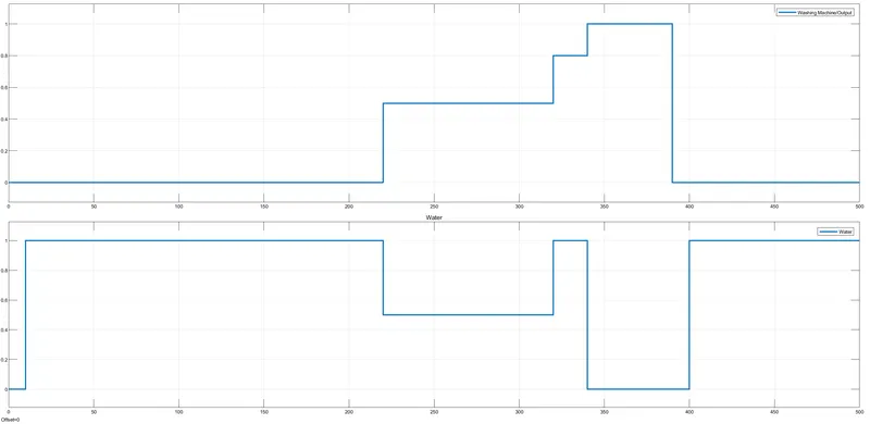
Fig.3: Simulink Output
The output can be visualized in form of a graph as well using the Simulink scope.
Gear Shift Logic:
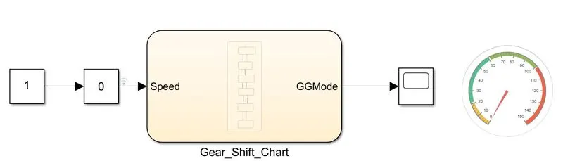
Fig.4: Simulink model - Gear shift Mechanism
This is a simple model to visualize the logic of the gear shifting mechanism. The whole logic is placed inside a state called GG to display the state names as output in the scope. This model contains a slider gain block that controls the speed manually and the gears shift based on the speed. Speed can also be visualized as output in the speedometer.
As slider gain is used, it is better to run the model for inf time so that it can be changed and results can be visualized more clearly.
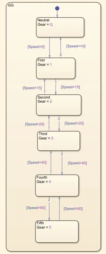
Fig.5: Chart for Gear transmission
When the speed input is given from slider gain,
- GG state gets activated automatically and enters the default state Neutral
- When speed is more than 1, the First state gets activated.
- Likewise, all the states are activated when the corresponding speed is set by the slider gain.
To display the gear position names in scope, enum data type is used. The check box in State output properties is checked and the data name and Enum name can be edited.
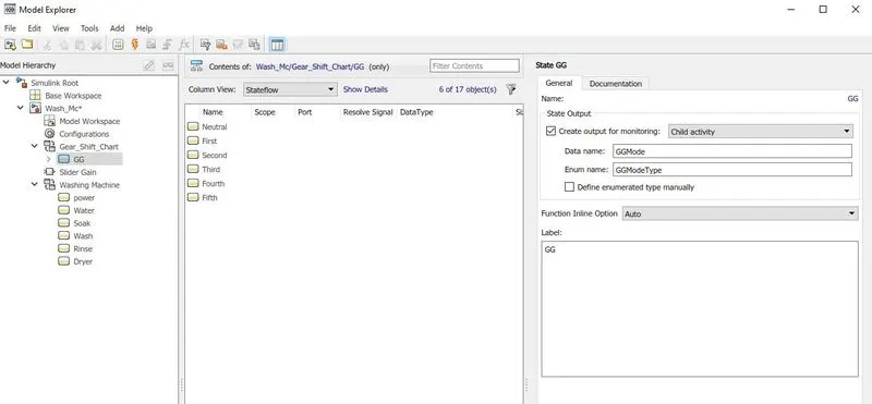
Fig.6: To display enum type for scope
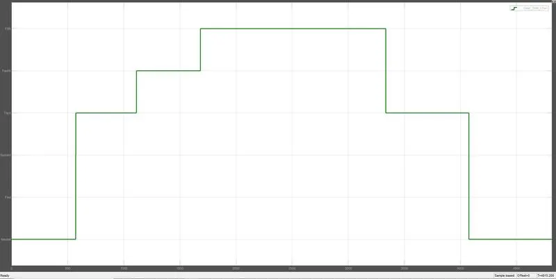
Fig.7: Scope output - Gear shift mechanism
Conclusion:
Thus, the control logic for a washing machine and a gear shift logic were implemented using state charts and the outputs were analyzed.