Week -2
OBJECTIVE:
The two main objectives of this challenge are to make a Simulink model of a doorbell using a solenoid and also build a Simscape model of a thermistor using defined temperature values.
Model 1:
Doorbell using Solenoid:
Theory:
From the figure given below, a simple mechanism of a doorbell can be visualized. The wound coil is the solenoid and it acts as an electromagnet.
When the circuit is closed using the switch, the battery activates the electromagnet and attracts the plunger of the bell and the circuit opens when it leaves the screw thus making it retract to its previous position and this continues making the plunger hit the continuously until the switch is in ON condition.
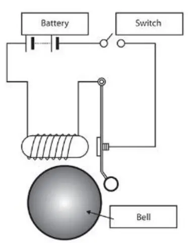
Fig.1: Doorbell Mechanism[1]
Every Simscape model must have the following blocks,
- Solver Configuration: To define the type of solver to solve the differential equation.
- Simulink-PS Converter: To convert the signal from Simulink block to executable physical system signal.
- PS-Simulink Converter: To convert the Physical system signal to a Simulink signal for further operation or output visualization.
- References: Mechanical: Must be given for mechanical Systems and the connection colour is green.
Electrical: Must be present in an electrical system model and the connections are in blue.
Thermal: Must be present for every thermal system model and the connections are given in orange.
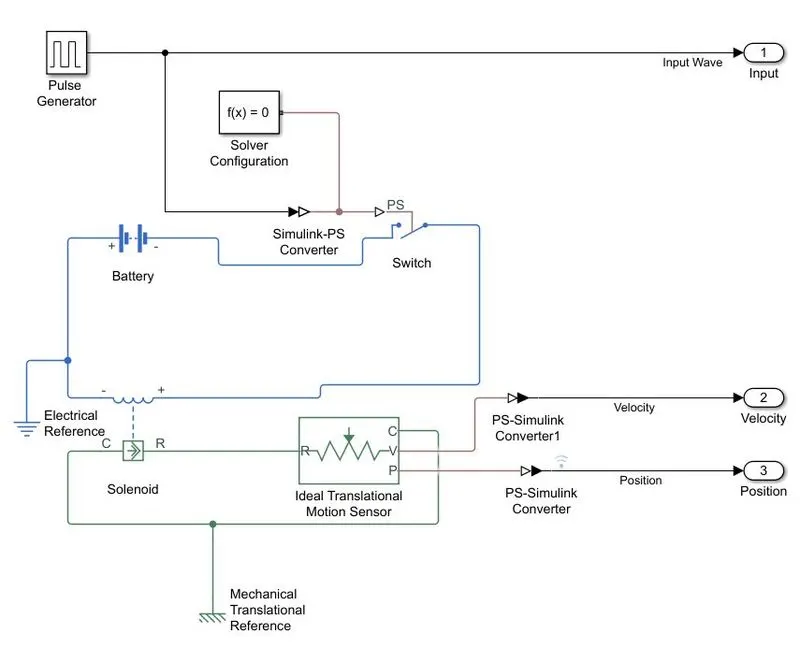
Fig.2: Doorbell Subsystem - Simulink Model
A pulse generator is used as input for this model because the requirement of the model was to hold the switch for 2 seconds and the parameters are adjusted according to the specification. The model was run for a total of 10 seconds so nearly three pulses were generated. Amplitude is the height of the pulse and period is the total time for the entire pulse. So, the pulse width is the rate at which the pulse is high. It is represented in percentage. A small phase delay of 0.5 secs is given to begin the pulse from 0.5 secs to clearly visualize them.
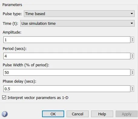
Fig.3: Pulse Generator - Parameters
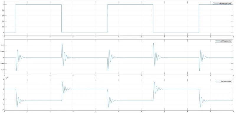
Fig.4: Simulink output for a doorbell - Less damping
The output above in fig.4 explains how the bell plunger changes its position. It has a lot of waves because a very less damping value(1 N/(m/s)) was specified in the solenoid block. When the damping value was changed to a higher value(10 N/(m/s)), a much smoother curve was obtained as shown in fig.5 and this denotes the smooth translational motion of the plunger.
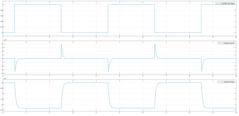
Fig.5: Output of doorbell Simulation - High Damping
Model 2:
Thermistor with fan control:
Theory:
A thermistor is a type of resistor where the electrical resistance changes with temperature. Even a slight fluctuation in temperature will cause the resistance of the resistor to change and its sensitivity is very high[2].
A fan must be also controlled when the temperature exceeds 25 degrees and turns off when it reaches below 25 degrees.
The entire model for the control is shown below.
The thermistor is powered by the battery and the temperature source acts as the input for it. A voltage sensor is given to measure the voltage across the resistor. The voltage varies as the temperature varies. A threshold value for Voltage must be found when the temperature is at 25 degrees. So, when the voltage exceeds the threshold value, the switch block gets activated and the fan is turned on. When it is below the threshold value the switch block gets deactivated. For easy visualization, the lamp from the dashboard is connected with the output signal of the control swtich. When the control switch is active, the ON lamp glows in GREEN, likewise when the switch is inactive the OFF lamp glows in RED.
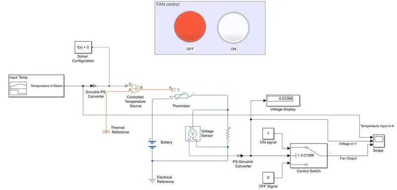
Fig.6: Thermistor with fan control - Simulink Model
The temperature control was achieved by the Signal builder block. The temperature changes were specified only for 50 seconds and the simulation was executed for the same time period. The temperature had to be converted to kelvin to make them accessible by the Simulink-PS converter block.
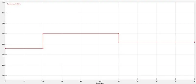
Fig.7: Signal builder
As shown below in fig.8 the input handling parameters were changed to first-order filtering to make it executable by the Physical system. Also, Units were specified to K(Kelvin).
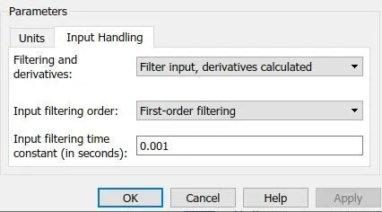
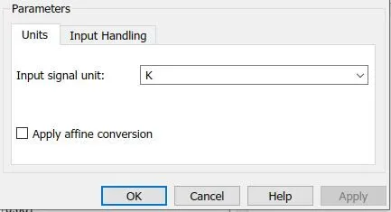
Fig.8: Simulink - PS Converter Parameters
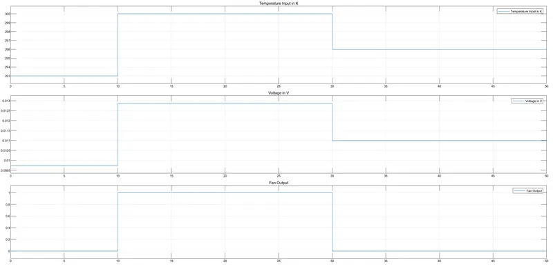
Fig.9: Thermistor and fan Output
From the output above it is clear that the temperature input was accurate according to the specifications and the corresponding voltage value from the sensor. The bottom graph shows when the fan switch was activated.
Link for Simulink Model:
Thermistor Model - https://drive.google.com/file/d/1UzDLrpUVN2mrqKOVRYxhipN8sCpKlfNy/view?usp=sharing
Doorbell Model - https://drive.google.com/file/d/1HD30Dp2wMKDVDHhm4_oowsEeOO5FE_g6/view?usp=sharing
Conclusion:
Thus the doorbell simulation using the solenoid was done in Simulink and the results were analyzed. Also, a thermistor control was modelled with control for a fan when the temperature exceeded. Both the models showed desired results.
References:
[1] Skilllync: Simulink for Mechanical and Electrical Engineers: Week 2: Challenge
[2] Online: Accessed:21.08.2021 https://www.electrical4u.com/thermistor/