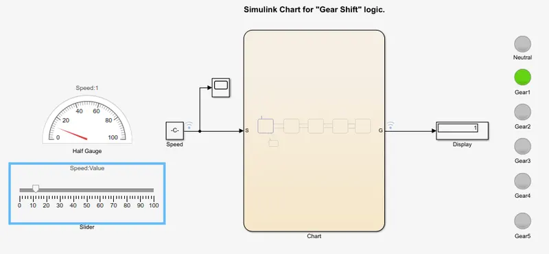
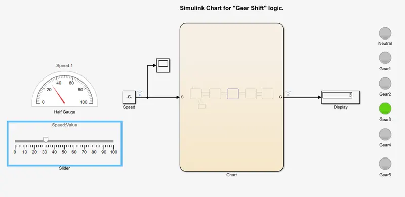
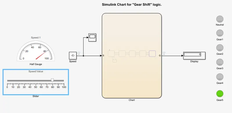
Simulink state flow model for a Washing machine process and Gear shift in an automobile transmission.
- Implement control logic of a “washing machine” using Stateflow as per given sequence:
- If the power supply is available, the system gets activated
- If the Water supply is not available, stop the process & indicate through LED
- Soaking time should be 200s followed by Washing time of 100s.
- Then rinsing happens for next 20s & dryer runs for 50s
After all the processes have completed turn on the finished LED
Steps taken:
- In Simulink window open up ‘state flow chart’.
- Within state flow, create 7 state blocks and interconnect them using appropriate logic and conditions as shown below.
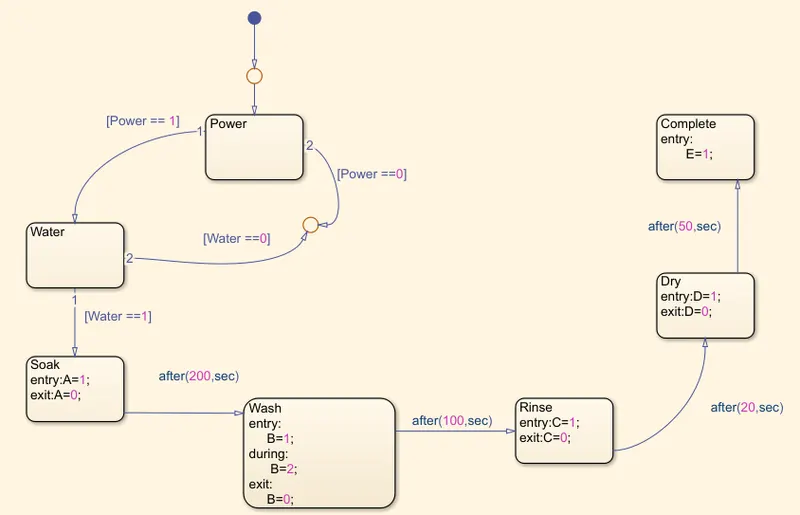
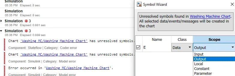
- After running the simulation, if we get an error as shown below. Then we should make sure to resolve all unresolved symbols by using symbol wizard. Basically, here we need to specify wether the symbol used will take input or give output.
- Now, come out of the state flow chart and provide input via ‘Rocker switch’. And take output trough the display and lamps, as shown below.
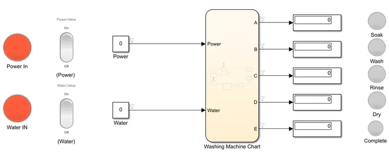
- Fix the simulation time as 400seconds, so that all the process can be executed.

- Proceed with the simulation by turning on water and power supply.
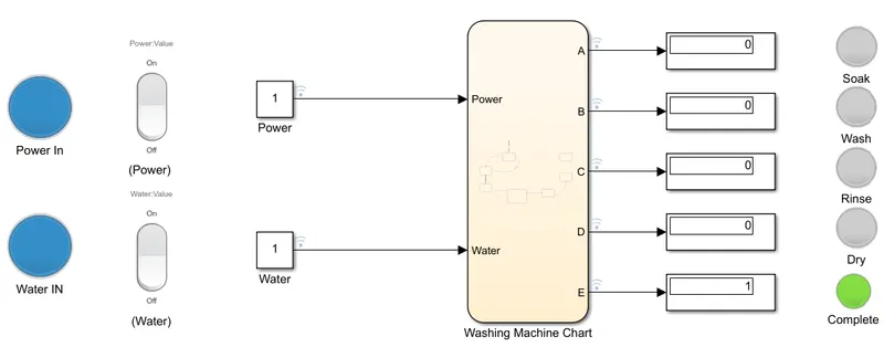
Results at different conditions:
- Power off but water supply on.
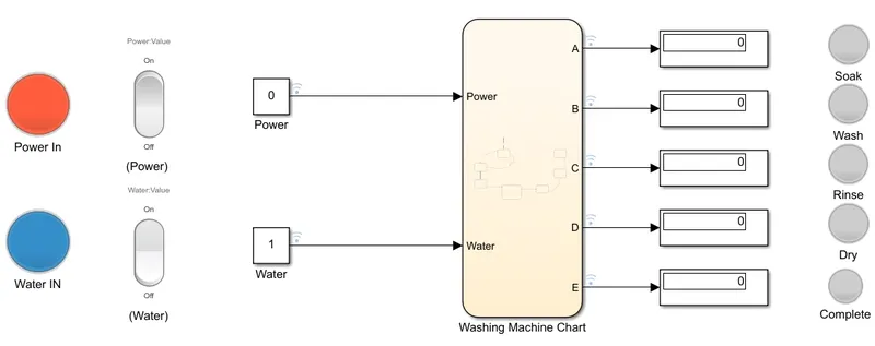
- Power on but water supply off.
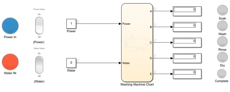
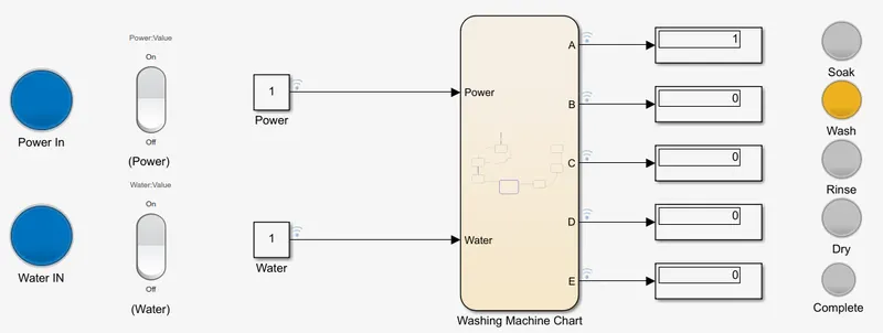
- While simulation is in wash mode.
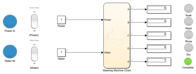
- When all the processes are complete.
- To Make a Simulink chart for the “Gear shift” logic as per below conditions:
|
Speed Range (kmph) |
Gear |
|
0 to 15 |
1 |
|
16 to 25 |
2 |
|
26 to 40 |
3 |
|
41 to 60 |
4 |
|
Above 61 |
5 |
Give speed input while the simulation is running & display the gear number.
Steps taken:
- In Simulink window open up ‘state flow chart’.
- Within state flow chart, create 5 state blocks for 5 gears and an additional state block for neutral gear.
- Interconnect all the state blocks using appropriate logic and conditions as given below.
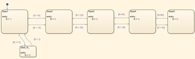
- After running the simulation, if we get an error as shown below. Then we should make sure to resolve all unresolved symbols by using symbol wizard. Basically, here we need to specify wether the symbol used will take input or give output.
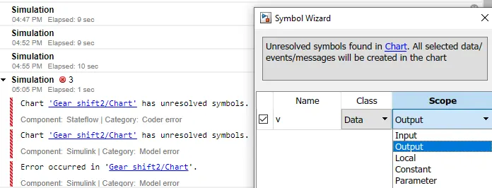
- Now, come out of the state flow chart and provide input via slider. And take output trough the display and lamps, as shown below.
- To use the slider within the simulation, put simulation time as infinity.

Results at different speeds: