Week - 4
MODEL-1
AIM:
To implement control logic of a “washing machine” using Stateflow as per given sequence
OBJECTIVE:
- If the power supply is available, the system gets activated.
- If the Water supply is not available, stop the process & indicate through LED.
- Soaking time should be 200s followed by Washing time of 100s.
- Then rinsing happens for next 20s & dryer runs for 50s.
- After all the processes have completed turn on the finished LED.
OBSERVATION:
- Display - The block shows the value of the input data. We can specify the frequency of the display.
- Constant - The block generates a real or complex constant value signal.
- Slider switch - The block toggles the value of the connected block parameter between two values during simulation.
- Stateflow - The block that provides a graphical language that includes state transition diagrams, flow charts, state transition tables, and truth tables.
- State - To initialize Simulink blocks when switching between Simulink based states, use Stateflow textual notation or Simulink State Reader and State Writer blocks.
- Lamp - The block displays a color to indicate the value of the input signal.
PROCEDURE:
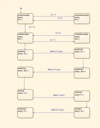
- The stateflow diagram was first created for the given objectives using states and its conditions.
- The first block has power supply, if the power is on the condition is P=1 or else the power is off then the P=0.
- The next blockis water supply to indicate the water supply is on W=1, incase off then W=0.
- Then proceed the next blocks with the given functions to be done by the washing machine (Soak, wash, rinse,dry)
- The time conditions to operate the function is specified as after(time,sec) and the time is given in objective.
- Later the completion of all the operations the finished block turns 1 or else 0.
- Each operations and its conditions are connected to the separate lamps to represent on or off.
- The power supply and water supply are represented by constant block if supply is on 1 or the supply is off then 0.
- The outputs of state flow is shown in display block for each operations.
- The supply is controlled by slider switches.
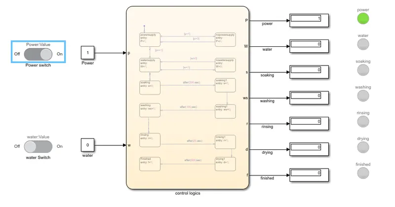
- If power supply is given, then the machine gets activated.
- If the water supply is not given then the whole process stops and indicated in indicator.
- Thus the water and power supply is on the each operations are done for the represented time.
- And the finished indicator is glown.
SIMULNK BLOCK DIAGRAM:
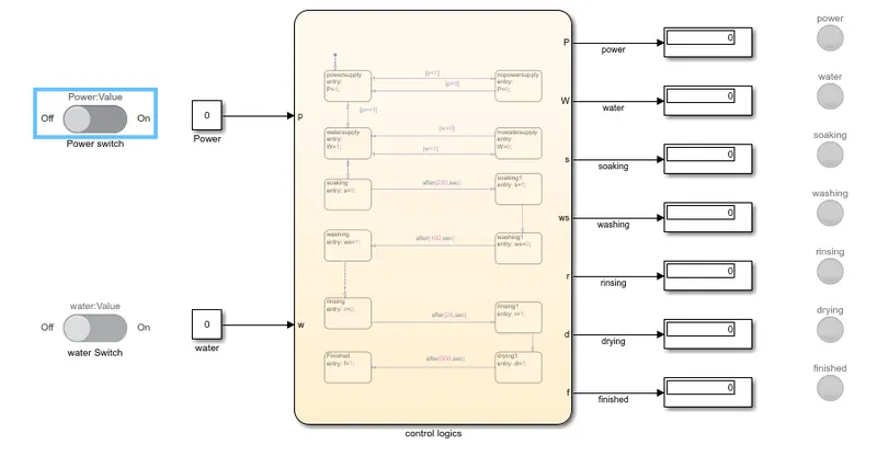
If the power supply is available, the system gets activated and If the Water supply is not available, stop the process & indicate through LED
STATE FLOW DIAGRAM:
RESULT:
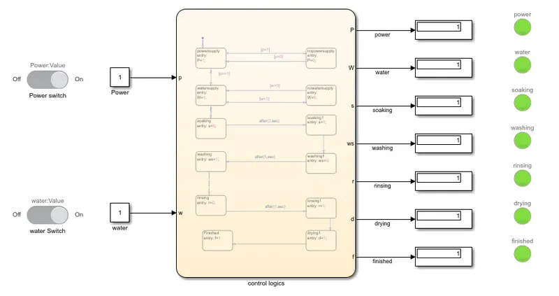
Hence the power and water supply is ON and the following operations are done at given time.
- Soaking - 200 seconds
- Washing - 100 seconds
- Rinsing - 20 seconds
- Dryer - 50 seconds.
https://drive.google.com/file/d/1FWT-XNS9ke_tRW6W_nI4BBAVBInI7YVg/view?usp=sharing
MODEL-2
AIM:
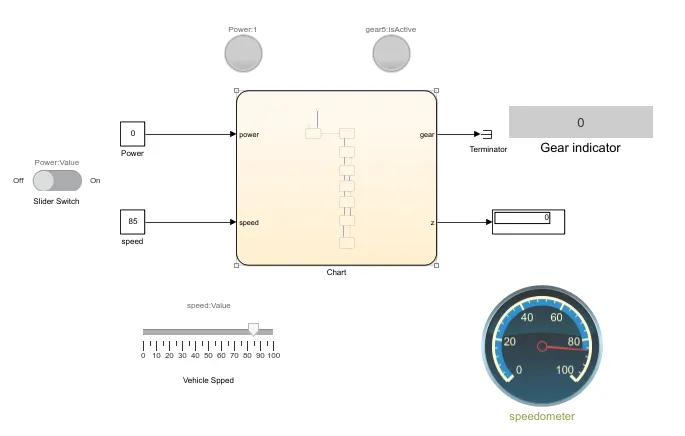
To Make a Simulink chart for the “Gear shift” logic for the given conditions. And Give speed input while the simulation is running & display the gear numbe
OBJECTIVE:
Speed Range(kmph) Gear
- 0 to 15 1
- 16 to 25 2
- 26 to 40 3
- 41 to 60 4
- Above 61 5
OBSERVATION:
- Display - The block shows the value of the input data. We can specify the frequency of the display.
- Constant - The block generates a real or complex constant value signal.
- Slider switch - The block toggles the value of the connected block parameter between two values during simulation.
- Slider - The block tunes the value of the connected block parameter during simulation.
- Stateflow - The block that provides a graphical language that includes state transition diagrams, flow charts, state transition tables, and truth tables.
- State - To initialize Simulink blocks when switching between Simulink based states, use Stateflow textual notation or Simulink State Reader and State Writer blocks.
- Lamp - The block displays a color to indicate the value of the input signal.
- Terminator - The block can be used to cap blocks whose output ports are not connected to other blocks.
- Circular gauge - The displays the value of the connected signal on a circular gauge that you can design to look like a gauge in a real system.
PROCEDURE:
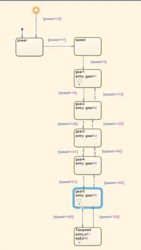
- The stateflow diagram was first created for the given objectives using states and its conditions.
- The first block has power supply, if the power is on the condition is 1 or else the power is off then the condition is 0.
- The next block is speed block which act as accelerator to modify the speed.
- Then proceed the next blocks with the given functions to be done for gear shifting mechanism (1,2,3,4 & 5)
- The speed conditions to operate the shifting mechanism is specified value and increment,decrement symbol(<,>,=)
- Later the completion of all gear blocks enter another block for top speed as z .
- Each gear and its speed value are connected to a terminator to end the output value.
- The power supply and accelerator are represented by constant block if supply is on 1 or the supply is off then 0.
- The outputs of state flow is shown in display block and speedometers as slider, circular gauge.
- And also the gear number is represented by gear indicator display block
- The power supply is controlled by slider switches and indicated by lamp.
- Also the top speed is indicated by another lamp with other color.
SIMULNK BLOCK DIAGRAM:
STATE FLOW DIAGRAM:
RESULT:
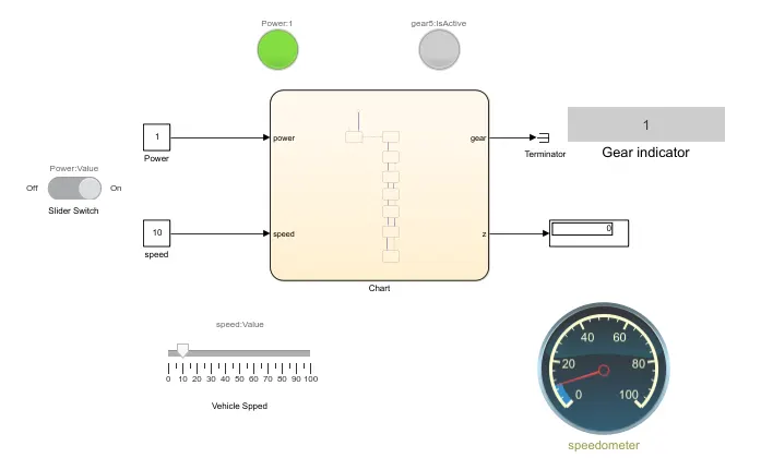
Condition 1 - Speed 10 kmph and gear number 1
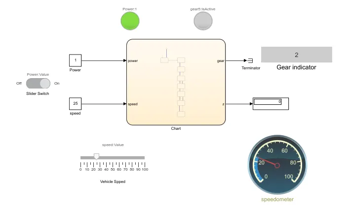
Condition 2 - Speed 25 kmph and gear number 2
Condition 3 - Speed 35 kmph and gear number 3
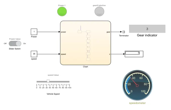
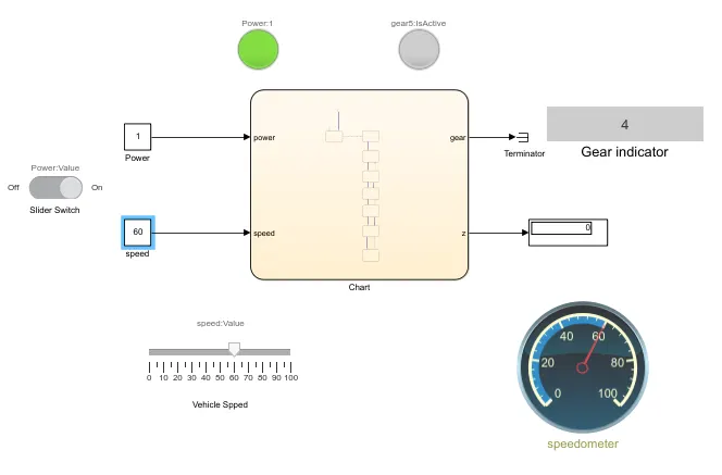
Condition 4 - Speed 60 kmph and gear number 4
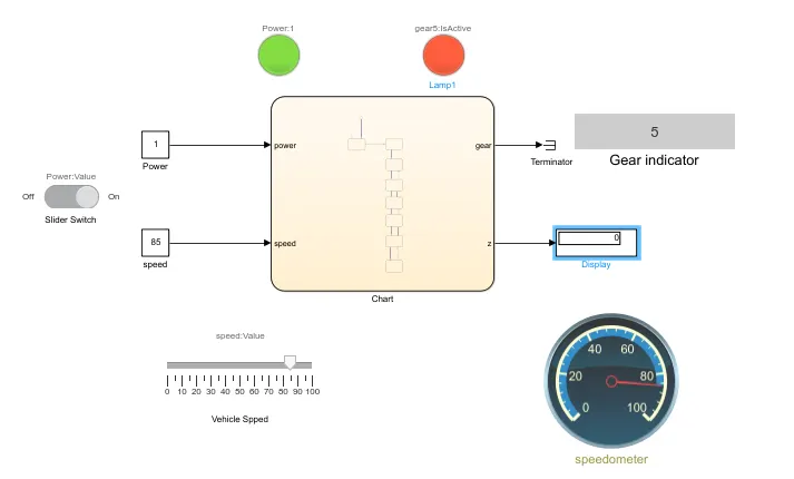
Condition 5 - Speed 85 kmph and gear number 5 with top speed indicator
https://drive.google.com/file/d/1TXF59OCyLbROt4bXP0ChmOL9A_Is87rK/view?usp=sharing