Washing Machine process and Gear Shifting Transmission using Stateflow.
Aim:
To create a Simulink model for the Washing Machine process and Gear Shifting Transmission using Stateflow.
Objective:
- Implement control logic of a “washing machine” using Stateflow as per given sequence:
- If the power supply is available, the system gets activated
- If the Water supply is not available, stop the process & indicate through LED
- Soaking time should be 200s followed by Washing time of 100s.
- Then rinsing happens for the next 20s & dryer runs for 50s
After all the processes have been completed turn on the finished LED.
- Make a Simulink chart for the “Gear shift” logic as per the below conditions:
| Speed Range(km/hr) | Gear |
| 0 to 15 | 1 |
| 16 to 25 | 2 |
| 26 to 40 | 3 |
| 41 to 60 | 4 |
| Above 61 | 5 |
Give speed input while the simulation is running & display the gear number.
Introduction:
Washing machine:
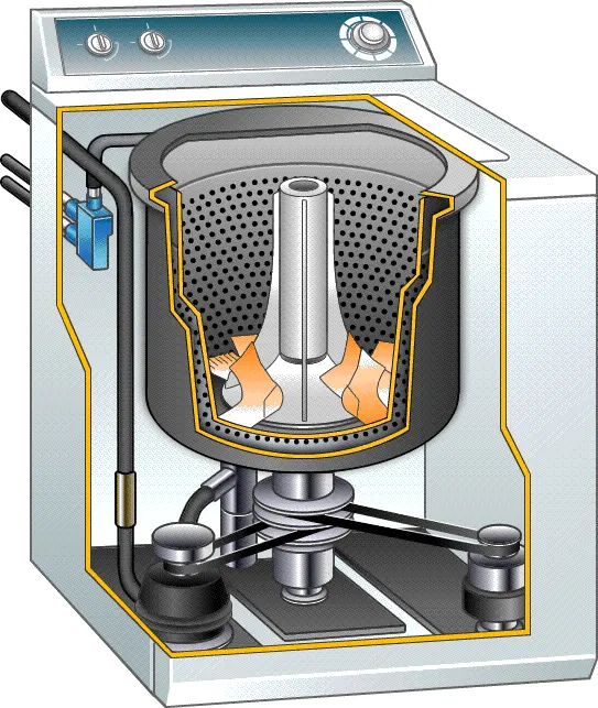
A washing machine is a machine that washes dirty clothes. It contains a barrel into which the clothes are placed. This barrel is filled with water and then rotated very quickly to make the water remove dirt from the clothes. Most washing machines are made so that detergent (liquids or powders) can be put into the machine. These can help make the clothes cleaner.
There are two types of Washing Machine;
1. Top-Load Washing machine
2. Front-Load Washing machine
Control Logic:
Control logic is a key part of a software program that controls the operations of the program. The control logic responds to commands from the user, and it also acts on its own to perform automated tasks that have been structured into the program.
Stateflow:
Stateflow is a control logic tool used to model reactive systems via state machines and flow charts within a Simulink model.
Stateflow® provides a graphical language that includes state transition diagrams, flow charts, state transition tables, and truth tables. You can use Stateflow to describe how MATLAB® algorithms and Simulink® models react to input signals, events, and time-based conditions.
Stateflow is generally used to specify the discrete controller in the model of a hybrid system where the continuous dynamics (i.e., the behavior of the plant and environment) are specified using Simulink.
Specific applications for Stateflow include:
- Mode logic, where each discrete model of a system is represented by a state.
- Fault management, where the Stateflow chart is used to control how the system responds to faults and failures within a system.
- Task scheduling, where the Stateflow chart is used to schedule when specific tasks occur, either within the Stateflow chart or within the overall Simulink model.
Procedure:
- To implement the control logic, open the Simulink blank page.
- Double click on the blank space and type the chart block and select it.
- In the chart, block select the Stateflow block and name the ‘Power ON’ add exit point Start=1 which creates a function when the function run machine will start ON.
- Creating a water sensing block and giving an exit watersupply==1 such that allows the water to enter when the function runs and stops at watersupply==0.
- These Blocks are connected by the connecting lines which consist of a power supply logic which when switched on it follows the process created.
- Now, we have to create a Soaking block such that the water supply is given and logic is considered such that after 200 seconds the Soaking should be done.
- After soaking is done, the Washing block is created with the logic that the wash should be completed after 100 seconds.
- The next process after washing is rinsing. Rinsing is done for 20 seconds and then it is sent to the Drying Block.
- In the Drying Block, the clothes are dried for 50 seconds, and then the Machine Stops.
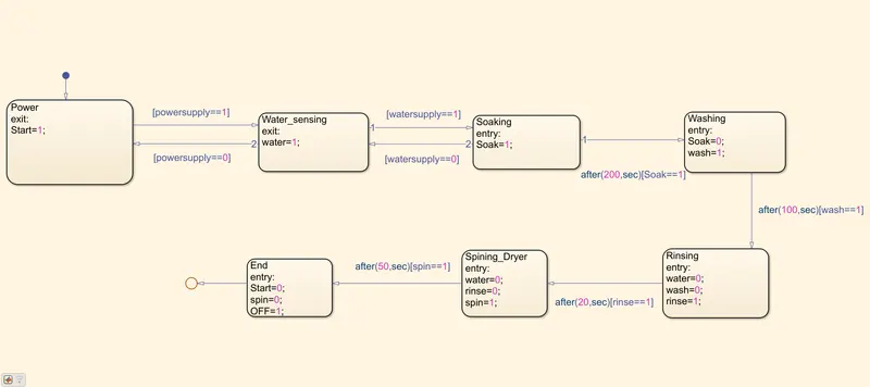
- After Creating the Required blocks, go to the Simulink workspace and save the file and make sure all the output and input connection ports are given properly.
- To check the ports, Go to the Chart Workbench, and in the prepare section, in the Configuration and Simulation, select the Symbols Pane. And check the ports and their sequence.
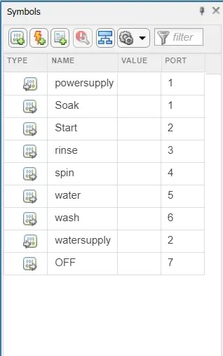
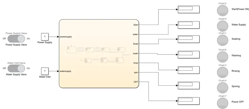
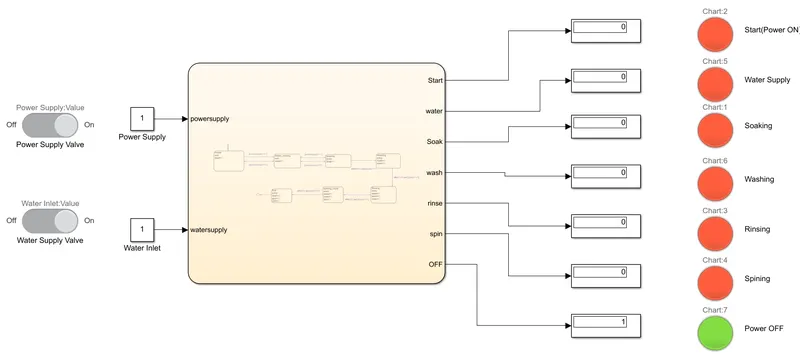
Now, in the Simulink workbench, give the output connections to display and the input connections as the constants.
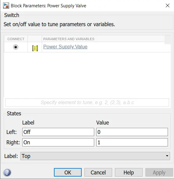
Now Lamps and Switches are connected to the outputs and inputs respectively.
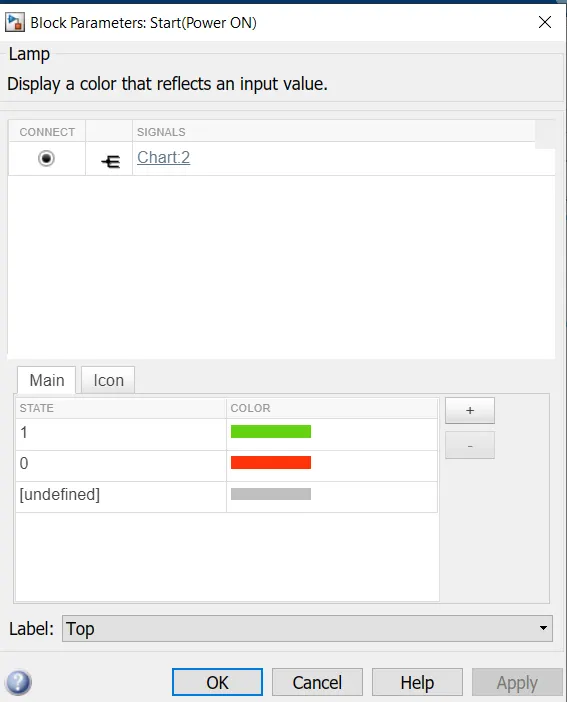
Run the simulation and observe the analysis.
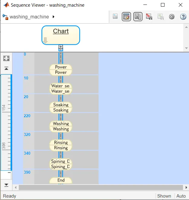
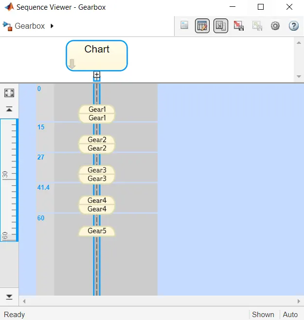
After Running the Simulation see the Sequence in the Sequence Viewer.
Gear shifting mechanism:
- The Gear shifting logic is created in the Chart state flow.
- Use the State block to create the different gears from 1 to 5 with entry as 1 and exit as 0.
- Now, Connect Gear 1 and 2 with a logic that if the Speed is greater than 16 then it shifts to Gear 2 and if the speed is less than 15 it changes to gear 1 from gear 2.
- Gear 2 and 3 also follow the same logic that if the speed is more than 26 it changes to gear 3 and if the speed is less than 25 it decreases to gear 2 from gear 3.
- Gear 3 and 4 also follow the same logic that if the speed is more than 41 it changes to gear 4 and if the speed is less than 40 it decreases to gear 3 from gear 4.
- Gear 4 and 5 also follow the same logic that if the speed is more than 61 it changes to gear 5 and if the speed is less than 60 it decreases to gear 4 from gear 5.
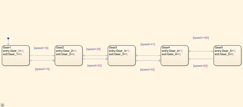
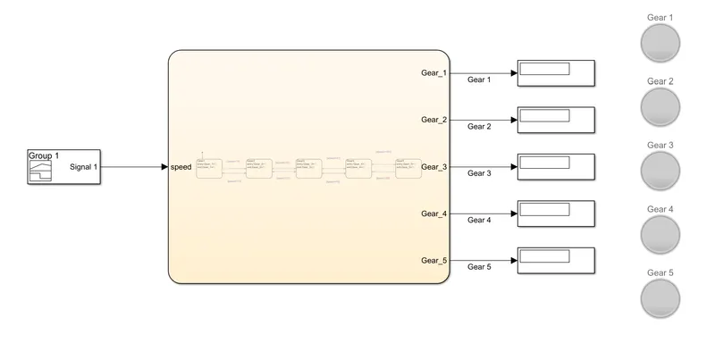
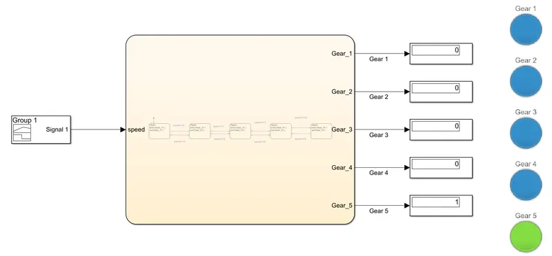
- Now, the connections are established and make sure that the output ports are given such that all the gears are considered as outputs and speed is taken as input.
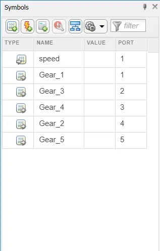
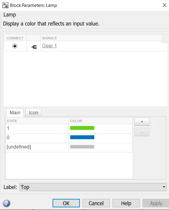
- For all the outputs the display blocks are created. The lamp is connected to the gears.
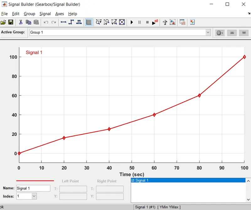
- The input signal builder is created with a graph created such that the speed increases.
- Run the Simulation and observe the results.
Sequence Viewer Box:
Results:
Washing Machine Logic:
Gear Shift Logic:
Conclusion:
The Washing Machine Logic and Gear Shift Logic Simulink model are created, implemented control logic by using Stateflow.