Week - 4
Aim : Implement control logic of a “washing machine” using Stateflow.
Objective :
- If the power supply is available, the system gets activated
- If the Water supply is not available, stop the process & indicate through LED
- Soaking time should be 200s followed by Washing time of 100s.
- Then rinsing happens for next 20s & dryer runs for 50s
After all the processes have completed turn on the finished LED
Washing Machine
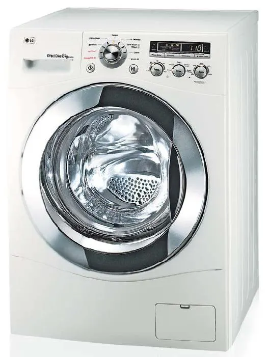
A washing machine (laundry machine, clothes washer, or washer) is a home appliance used to wash laundry. The term is mostly applied to machines that use water as opposed to dry cleaning (which uses alternative cleaning fluids and is performed by specialist businesses) or ultrasonic cleaners. The user adds laundry detergent, which is sold in liquid or powder form, to the wash water.
Stateflow
- Stateflow® provides a graphical language that includes state transition diagrams, flow charts, state transition tables, and truth tables. You can use Stateflow to describe how MATLAB® algorithms and Simulink® models react to input signals, events, and time-based conditions.
- Stateflow enables you to design and develop supervisory control, task scheduling, fault management, communication protocols, user interfaces, and hybrid systems.
- With Stateflow, you model combinatorial and sequential decision logic that can be simulated as a block within a Simulink model or executed as an object in MATLAB. Graphical animation enables you to analyze and debug your logic while it is executing. Edit-time and run-time checks ensure design consistency and completeness before implementation.
Simulink model of stateflow washing machine
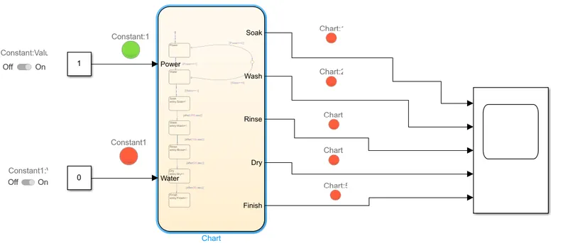
- To create stateflow washing machine model here used 'chart'.
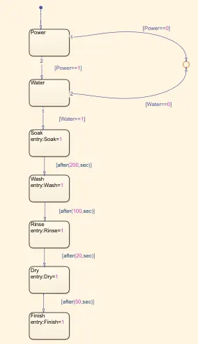
- Used different state blocks to describe state
- Inputed given condition such as
a) If the power supply is available, the system gets activated.
b) If the Water supply is not available, stop the process & indicate through LED.
c) Soaking time should be 200s followed by Washing time of 100s.
d) Then rinsing happens for next 20s & dryer runs for 50s.
e) After all the processes have completed turn on the finished LED.
-
The Simulink model showing the Stateflow chart, input ports and switches to turn ON and OFF the power and water with the output ports having all the washing machine states such as Soak, Wash, Rinse, and Dry, which are connected to a scope to visualise the output signals with the LEDs connected to all the output ports to check if that state is ON or OFF The Simulink model can be seen below.
Input and output ports:
- In this chart first state is Power where it detects if the input power is available or not, otherwise the machine will not turn on.
- Next state is water to detect availability of water if not it will not run.
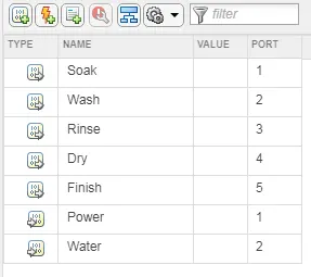
- Hence by making them as Input ports to the state flow and were connected to the ON and OFF slider switches which in general provides 0 or 1 as a signal as O is no input and 1 is input to the system.
- Therefore, a condition at these two states were given as if there is input 1 then the machine will run, that means the signal will passed through to run the states ahead. And if there is no input, a junction was inserted. where it was given a signal from power and water states of O which means if the input is O the cycle will not move forward and the function will be terminated, which means in Simulink if the switches are off with signal O the Stateflow will not work
- Next state is soak wih time delay 200 sec means after200 sec soaking process will stop and goes further state which is wash. In wash mode clothes asre washig for another 100 sec.
- After washing next state is rinse where clothes are rinse for another 20 sec. End state is Dry state where clothes are dry for 50 sec.
- First simulation is run for 10 sec to check availability of Power and where water switch is offed. If at this condition run the simulink model it shows LED of poer is ON and LED of water and others is OFF.
- After that the power and water switches were turned on for checking of the logic. where both the switches are turned ON and the simulation was run for 10 seconds we can see both water and power LEDs are ON with the Soak LED ON. Power and water switches ON hence the soaking starts.
- As the soaking period was 200 seconds the next simulation was ran for 210 seconds to check if the Wash cycle starts or not, the next figure shows us the washing LED ON, just right when the rinse cycle finishes, the washing starts and therefore turns ON the LED
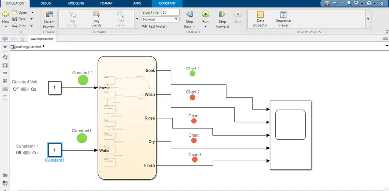
- The next step was to check the functionality of the Rinse cycle for which the simulation was ran for 330 seconds where, right after the wash cycle the rinsing started which can be seen in the figure below.
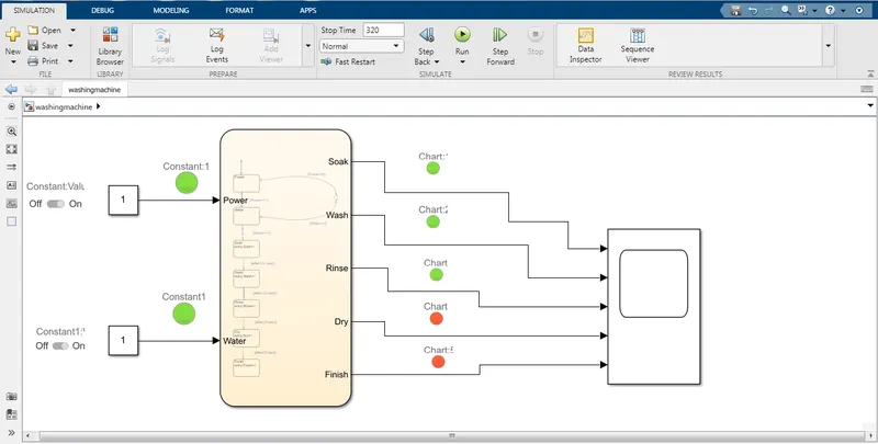
- After rinsing the Dry cycle needed to start therefore the simulation was ran again for 380 seconds, as after 20 seconds of rinsing, the drying cycle has to start. The next figure shows us the Dry LED ON.
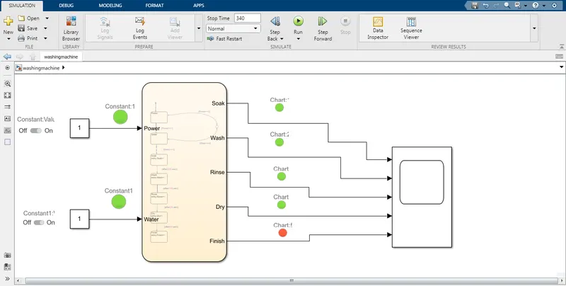
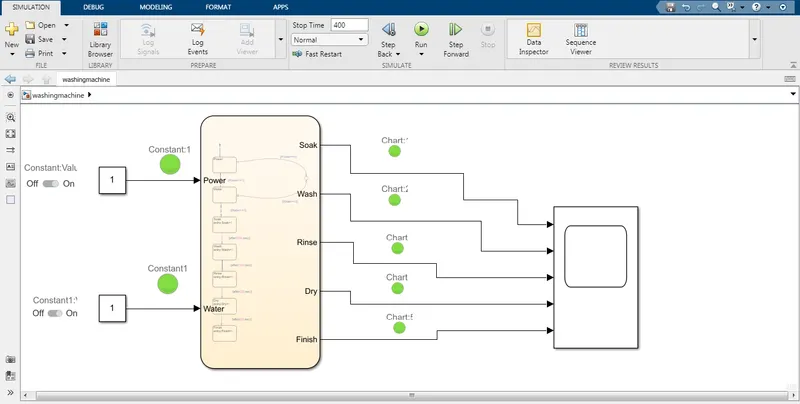
- Once the whole cycle completes the Stateflow was given a Finish output to show that the whole cycle of 370 seconds has finished. The next figure shows is the finished cycle LED ON which means the cycle was finished. This last simulation was running for total of 380 seconds where we can see all the LEDS ON.
Output :
Aim : Make a Simulink chart for the “Gear shift” logic.
Objective :
- Speed Range(kmph) Gear
0 to 15 1
16 to 25 2
26 to 40 3
41 to 60 4
Above 61 5
- Give speed input while the simulation is running & display the gear number.
Gearbox
Gearbox is a contained gear train, or a mechanical unit or component consisting of a series of integrated gears within a housing. In fact, the name itself defines what it is — a box containing gears. In the most basic sense, a gearbox functions like any system of gears; it alters torque and speed between a driving device like a motor and a load.
Simulink mode of stateflow gearbox
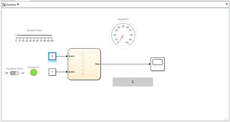
- Stateflow chart is made with given speed and gear conditions where different states are programed to speed
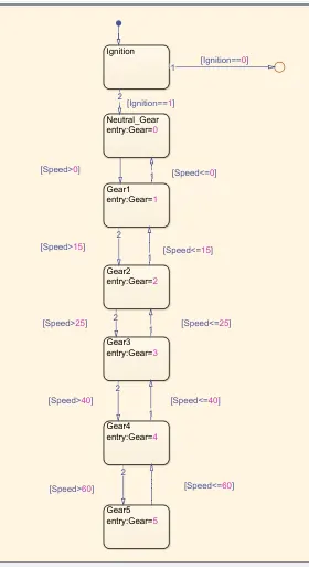
- Ignition state is given to checkd ignition is ON/OFF. If ignition is Offed tyhen flow will be terminated at junction
- Next state given is Neutral gear with condition vehicle is at 0 Km/hr will engage neutral gear.
- Then next state is given Gear 1 where speed is 0<x<15 km/hr. If speed is greater than 0 it will engage Gear1 and less than or equal to 0 then it will engage Gear1
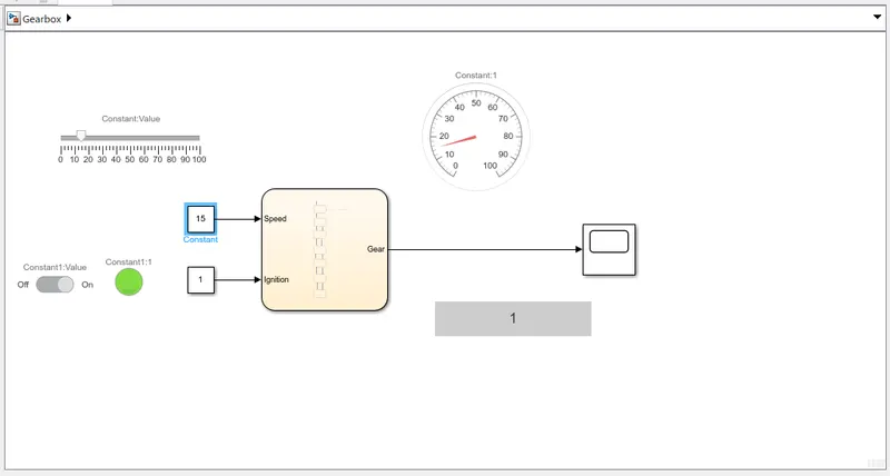
- First simulation is given for 100 sec and input speed 15 Km/hr.
-
Thereafter the second state is Gear2. which is implemented for the speed if the speed is greater than 15 Km/hr it will engage Gear2. If lesser than 15 Km/hr it will engage Gear1. Similarly, Gear3, Gear4, and Gear5 states were implemented with their respective speeds at that point of time.
- Then simulation is for 100 sec and speed 25 Km/hr.
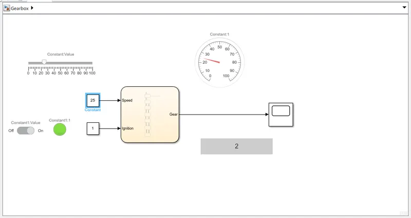
- Next simulation is for 100 sec and speed 40 Km/hr.
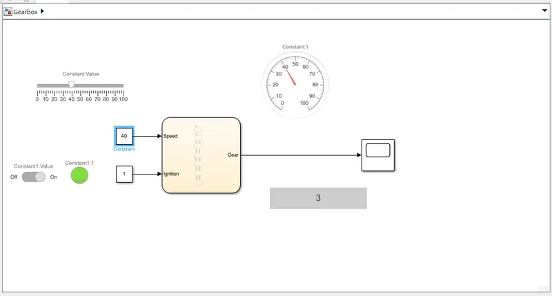
- Further simulation is for 100 sec and speed 60 Km/hr.
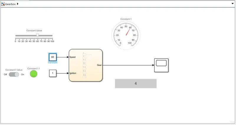
- Last simulation is for 100 sec and speed 70 Km/hr.
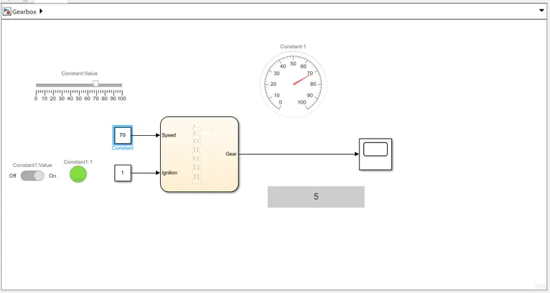
Output :
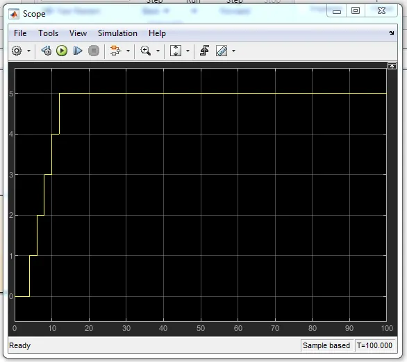
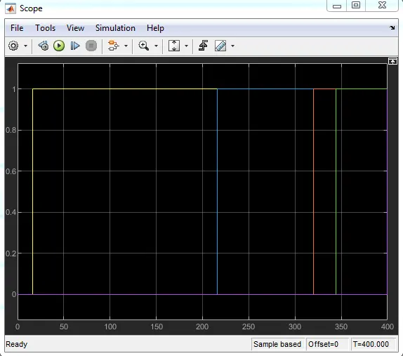
- Ouput in the scope is showing shifting of gear with respective given speed