Week 4-1D Element Creation Challenge
AIM:
Create 1D elements on the following component with the given cross-section and DOF.
Specification:
a. Rod element:- Translational DOF should be Constrained with RBE2 link
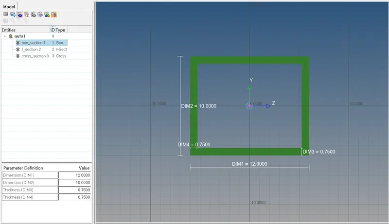
Cross-Section: BOX- Dimension a= 12 mm
dimension b=10 mm
Thickness t= 0.75 mm
b. Beam element:- All DOF should be constrained with RBE3 link
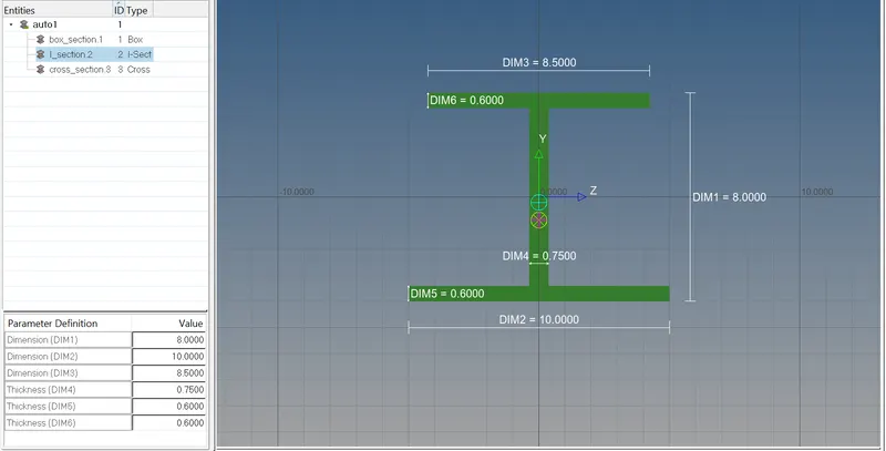
Cross-Section: I Section- Dimension a= 8 mm
Dimension b= 10 mm
Dimension c= 8.5 mm
Thickness t1= 0.75 mm
Thickness t2= .6 mm
Thickness t3= .6 mm
c. Bar element:- Constrain only x and y DOFs With RBE3 link
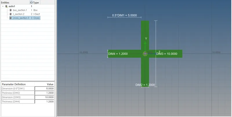
Cross-section: X section- Dimension DIM1= 5 mm
Thickness DIM2= 1.2 mm
Dimension DIM3= 10 mm
Thickness DIM4= 1.2mm
d. & e. Apply the mass of magnitude 10 with the RBE2 link
f. Join the two components with Spring elements.
Procedure:
1. Importing the geometry in the workspace and deleting the wireframe
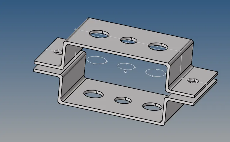
2. Creating the Mid surface for the given component:
Select the component and create a mid surface for bracket 1 top component by selecting the object.
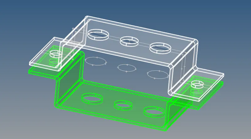
Select the component and create a mid surface for bracket 2 Bottom component by selecting the object.
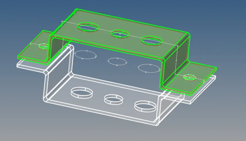
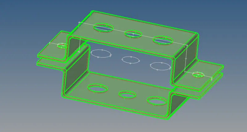
3. Meshing the component
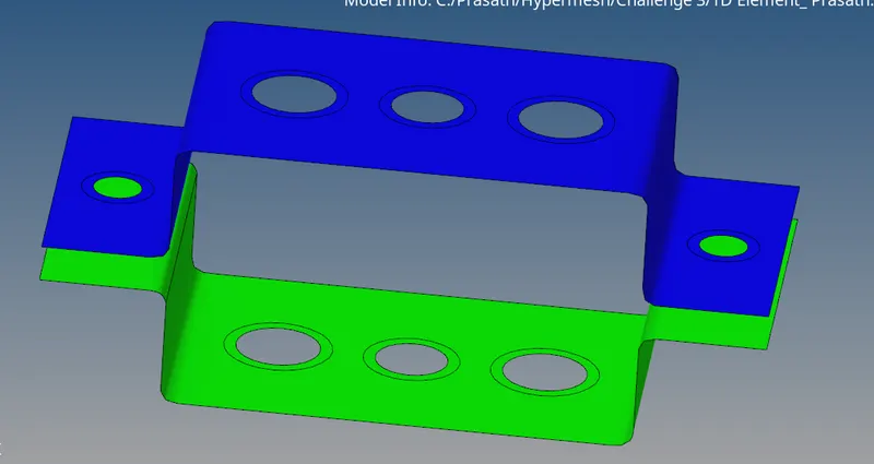
- TO mesh the given component, We need to create washer splits near the hole region for a smooth mesh, the washer split offset is 5mm.
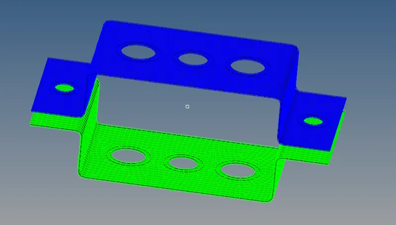
- generate the mesh with element size as 5mm with mixed element type.
4. Creat material:
steel as the material for the component
5. Creating Properties:
| Serial No | Property name | Card ID |
| 1 | Bracket 1 | PSHELL |
| 2 | Bracket 2 | PSHELL |
| 3 | Bar | PBAR |
| 4 | Rod | PROD |
| 5 | Beam | PBEAM |
| 6 | Mass | PMASS |
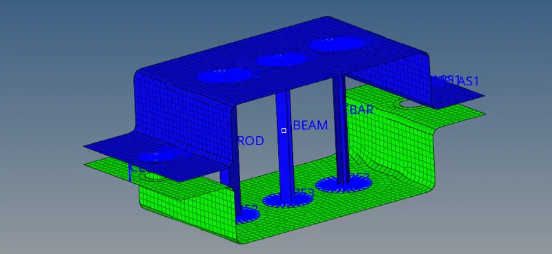
6. Create the 1D elements
To creat the 1D element we need to go the Hyper beam tool and select the representive Cross section for creating the 1D element and give the assigned dimension to the geometry as mentioned in the specification
7. Creating rigids at point a,b,c & d
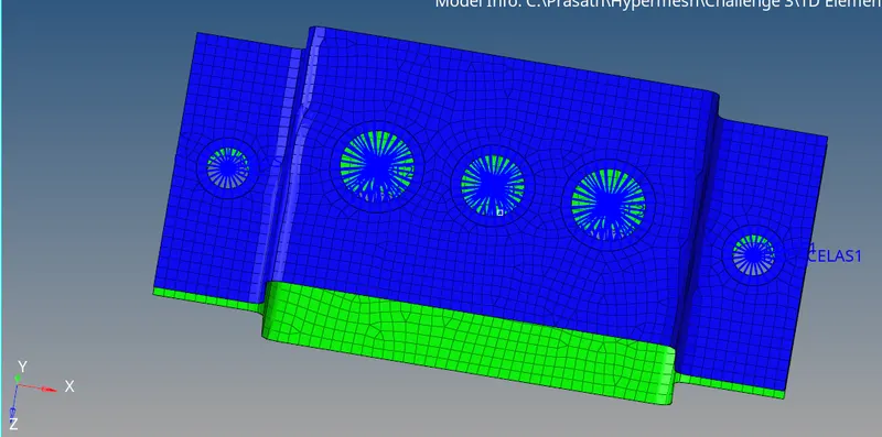
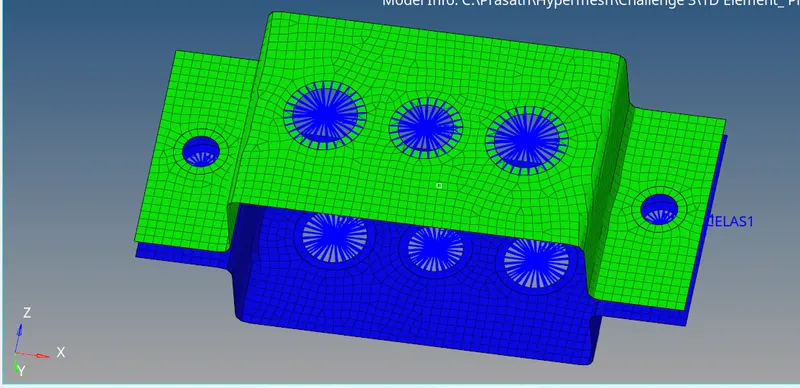
Creat the RBE2 and RBE3 at the respected holes and add mass with given DOF.
8. Creat the 1D element on the rigid:
creating the Rod, Bar , Beam 1D elements at the respective node points.
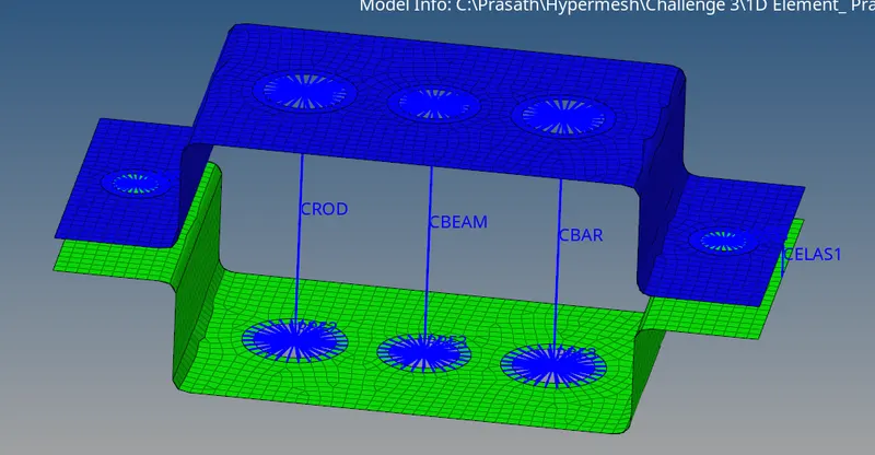
Update the Rod, Bar , Beam with property we assigned and added Mass of 10
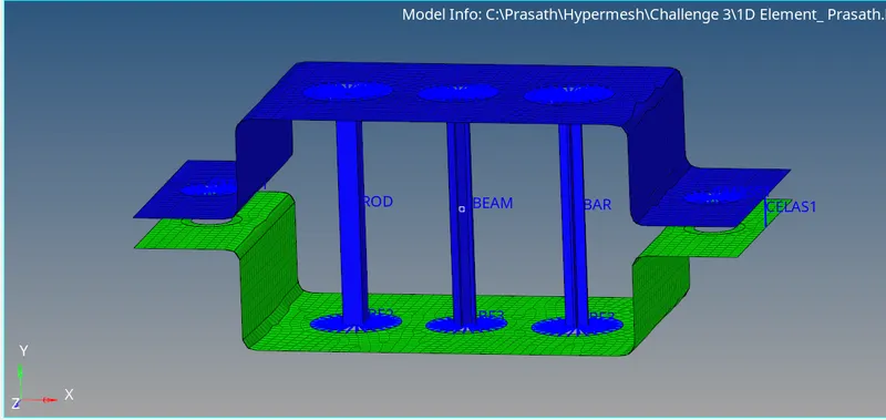
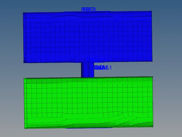
VIEWS:
Front view
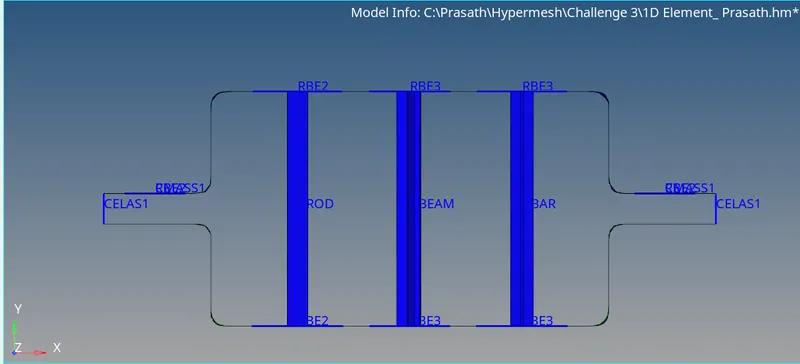
TOP view:
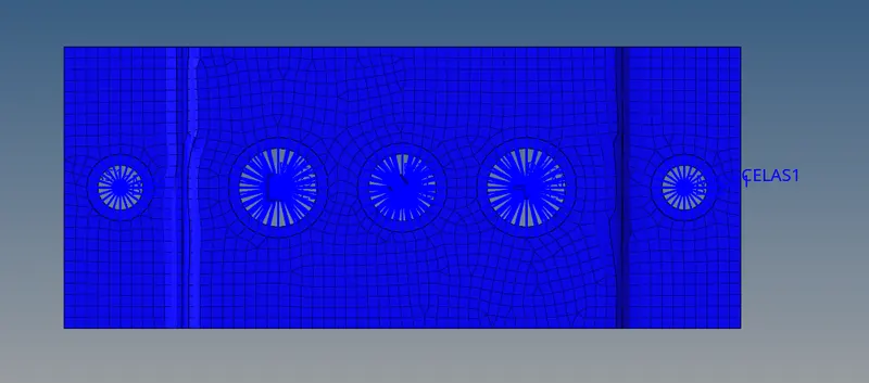
Bottom view:
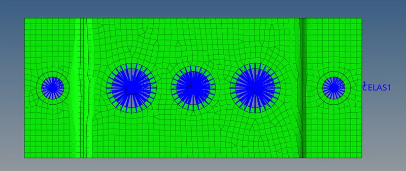
Side view:
Iso metric view:
Conclution:
• Extracted the mid-surface for the given component and Created a Mesh on the mid-surface
• Deployed suitable 1D Element ( RBE2, RBE3, ROD, BAR, BEAM , MASS, SPRING etc ) to the respective places.
• Assigned Cross-section and property to the 1D elements
• Created Solid representations of 1D Element.