To create 1D elements (Rod, Beam & x-section) and mesh the given component.
Mesh the Given component with the Size of 5 Units. Create 1D elements on the following component with given cross-section and DOF
- Rod element: - Translational DOF should be Constrained with RBE2 link
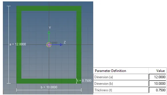
Cross-Section: BOX- Dimension a= 12 mm
dimension b=10 mm
Thickness t= 0.75 mm
- Beam element: - All DOF should be constrained with RBE3 link
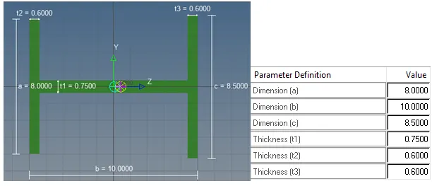
Cross-Section: I Section- Dimension a= 8 mm
Dimension b= 10 mm
Dimension c= 8.5 mm
Thickness t1= 0.75 mm
Thickness t2= .6 mm
Thickness t3= .6 mm
- Bar element: - Constrain only xand y DOFs With RBE3 link
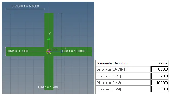
Cross-section: X section- Dimension DIM1= 5 mm
Thickness DIM2= 1.2 mm
Dimension DIM3= 10 mm
Thickness DIM4= 1.2mm
- & e. Apply the massof magnitude 10 with the RBE2 link
- Join the two components with Spring elements
Steps Taken:
Importing geometry:
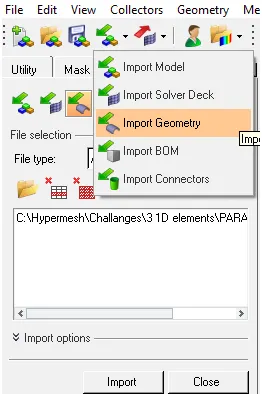
To import the Geometry we select ‘import geometry’ option from the tool bar then after browising the correct file and clicking on ‘import’, we will see our geometry in ‘Graphics Area’.
The imported geometry is a solid. A solid is a closed volume of surfaces that can take any shape. Solids are three-dimensional entities that can be used in automatic tetra and solid meshing. Its colour is determined by the component collector to which it belongs.
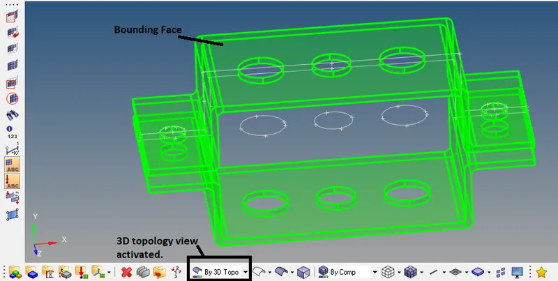
A bounding face is a surface that defines the outer boundary of a single solid. Bounding faces are shaded green by default.
Reparing CAD/ Geometry Cleanup:
To do the analysis it is important to import the CAD into the hypermesh to do the mesh. But sometimes the imported geomertry comes with topology errors. And often times we need to simpify the geometry to achieve a better mesh.
Click on ‘auto clean up’ that will make the edges coloured according to their topology status. To know what the colours mean, click on the ‘visualization’ option.
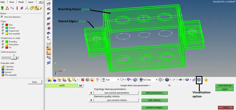
Since the edges are coloured green, the edges are shared edges. A shared edge is an edge that is owned, or shared, by two adjacent surfaces. When the edge between two surfaces is a shared edge (this is what you typically want to have), there is no gap or overlap between the two surfaces - they are geometrically continuous. The automesher always places seed nodes along the length of a shared edge and will produce a continuous mesh without any gaps along that edge. The automesher will not construct any individual elements that cross over a shared edge.
Red colour depicts free edges- they show where we might have missing connectivity or gaps. A close loop free edge shows a hole or a missing surface.
Yellow colour depicts non-manifold- they show edges where more than two surfaces share an edge. Which might be a T-connection or a duplicate surface.
Blue colour depicts Suppressed edges. Edges which are suppressed on purpose for some reason.
Since we don’t have any missing connectivity, gaps or duplicate surfaces, we will move to next step.
Generating Mid-surfaces:
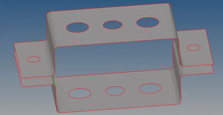
Mid surface is often used when we want to model in 2D such as sheet metal. And it can save a lot of time compare to a full 3D model. To generate the mid surface, go to the mid-surface option in ‘Geom’ page.
The make sure ‘auto mid surface’ and ‘closed solid’ are selected and then click on the model surface. Then click extract.

In the model tree can see a new component ‘Middle Surface’ is created the mid surface.
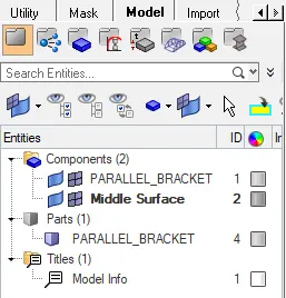
Turn off the geometry visualization of the model to see the mid surface.
Generating mesh for the midsurface:
Go to the 2D page and select the auto mesh option.

Select element seize as 5 and mesh type as mixed. Select all the surface and click mesh.

Checking Quality of the mesh:
Go to the tools page and click on ‘check elements’.

Usually the main matrix for mesh quality is skewiness and jacobian. If we click on skew and jacobian we will get following result.

We can check the Quality index by going to 2D-> Quality index. Which in this case is 46.08. Lesser the quality index better the mesh.

Refining Topology to achieve Quality mesh:
Go to Geom -> Point edit
Go to Geom -> Surface edit and trim the surface at the corners.

Putting split line in the middle of the circle:
Press f4
Press and hold the mouse over the circle. When the circle highlights, then place 3 nodes. Click on get centre. Finally press return to accept the changes and to go back to the previous menu.
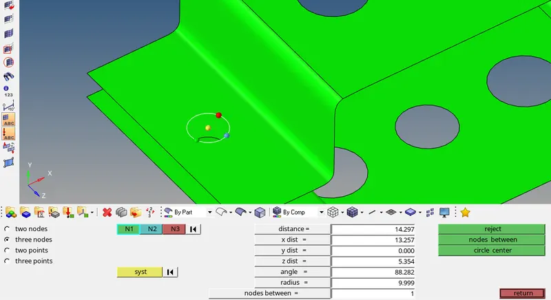
Go to Geom -> Surface edit -> trim with surf/plane
Now select 2 nodes and select base node as the circle centre.
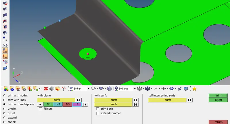
select trim.
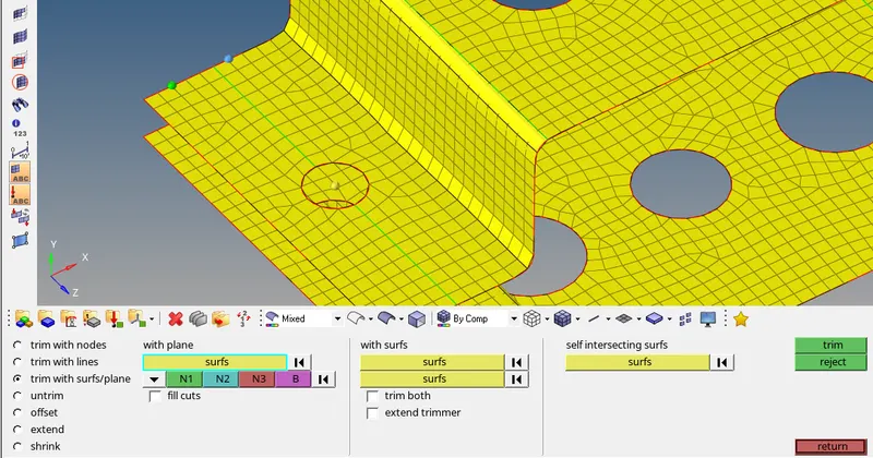
Go to Geom -> Quick edit –> split surf-line
Following this, divide the surface in parts.
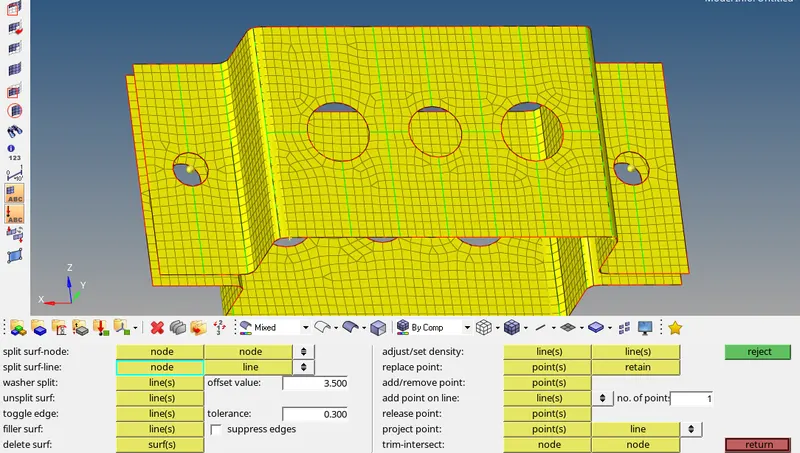
Go to 2D -> automesh

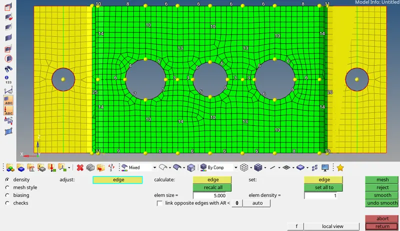
Final mesh with Quality index:
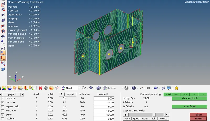
We can see the Quality index has improved.
Creating 1D element cross-section area (Box-section, I-section, Cross section):
Go to 1D then select Hyperbeam.

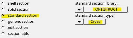
Go to ‘standard section’ and click the drop down to select the required sections.
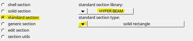
Below are the sections used in this exercise.

To get the ‘cross’ or 'x' section select ‘OPTISTRUCT’ library then select the required section.
- Box section
- I-section
- Cross-section
Creating 1D Beam element:
Go to 1D-> bars

Then select the property, element type and orientation of the beam. Then select node A and B.

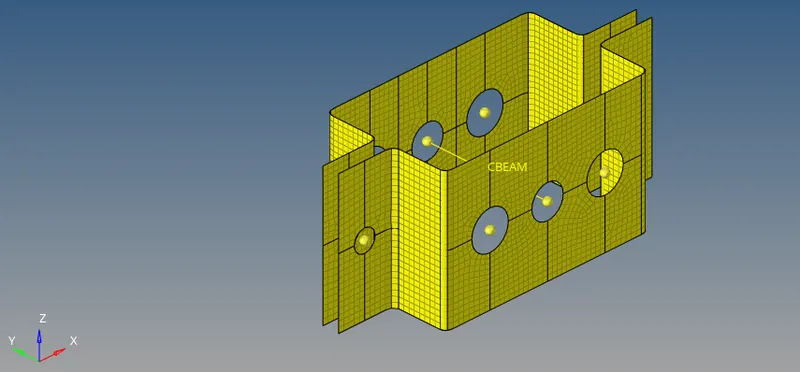
Similarly we can create 1D Bar and Rod elements.
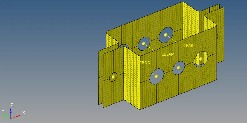
To check if the 1D elemets are created as per requirement, click on the following:
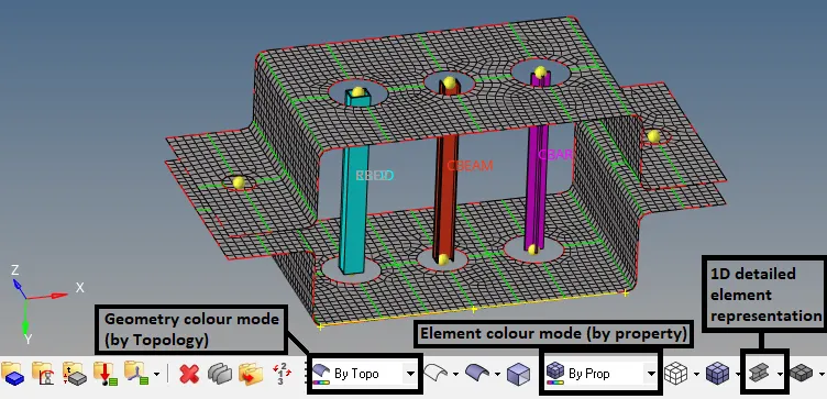
Applying Constraints:
- For Rod element with box cross-section, translational DOF should be Constrained with RBE2 link.
Go to 1D -> rigids

Here dof 1,2,3 means translation along x, y, z axis respectively. dof 4,5,6 means rotaion along x, y, z axis respectively.
If the ‘dof’ is checked then the dof is constraint or the movement is restricted. If ‘dof’ is unchecked then the element is free to move in that direction.
Now, select the node and the loops (after selecting create ‘multiple nodes’ in the drop down). And click on create.
Do this for the reverse side also.
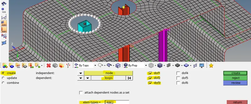
- For beam element with I-section, all DOF should be constrained with RBE3 link.
Go to 1D -> rbe3

Check all the dofs, select on the node and also select the loop. Click on ‘create’.
Do the same on the reverse side.
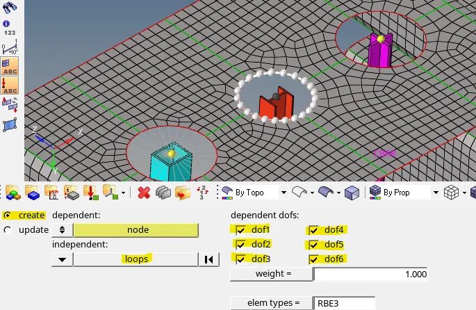
- For bar element with x-section we need to constrain only x and y DOFs with RBE3 link.
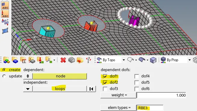
Applying the mass of magnitude 10 with the RBE2 link.
Apply the RBR2 link with all constraints, as done in previous step.
To place mass, click on the ‘masses’ on 1D page.

Then select the mass magnitude, element type and node. Lastly cilck on create.

Join the two components with Spring elements.
Go to 1D -> springs
Then select dof, property, element type and both the nodes.

Final Output:
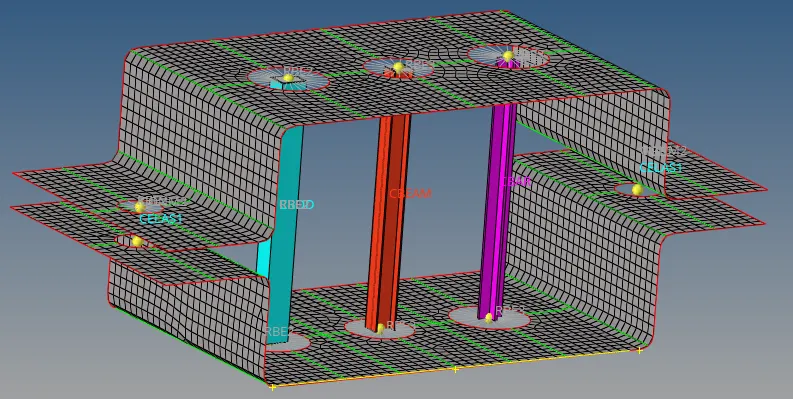
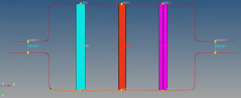
The Hypermesh model files (.hm) is attached below.