Week 4-1D Element Creation Challenge
Task
Mesh the Given component with the Size of 5 Units. Create 1D elements on the following component with given cross-section and DOF
a. Rod element:- Translational DOF should be Constrained with RBE2 link
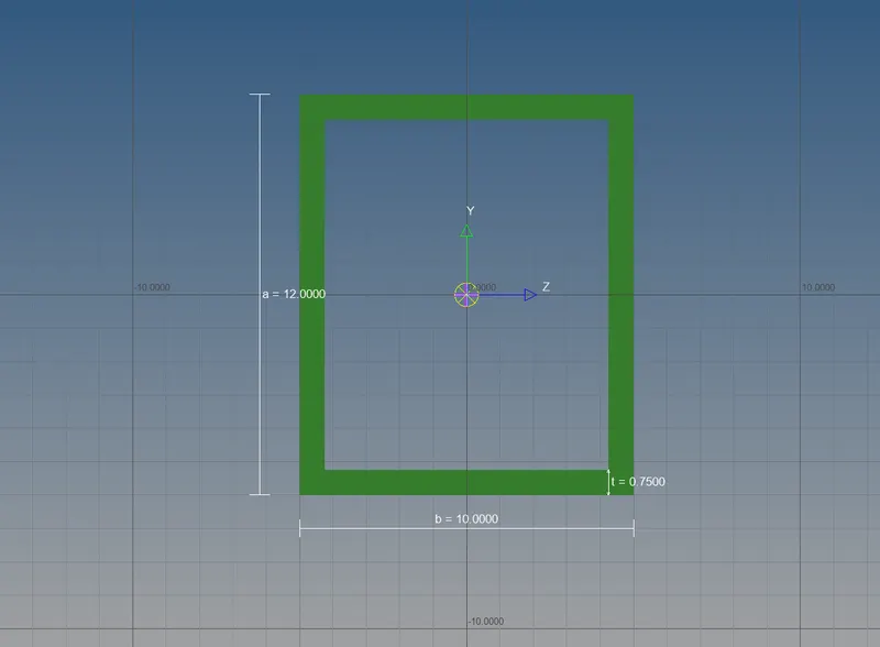
Cross-Section: BOX- Dimension a= 12 mm
dimension b=10 mm
Thickness t= 0.75 mm
b. Beam element:- All DOF should be constrained with RBE3 link
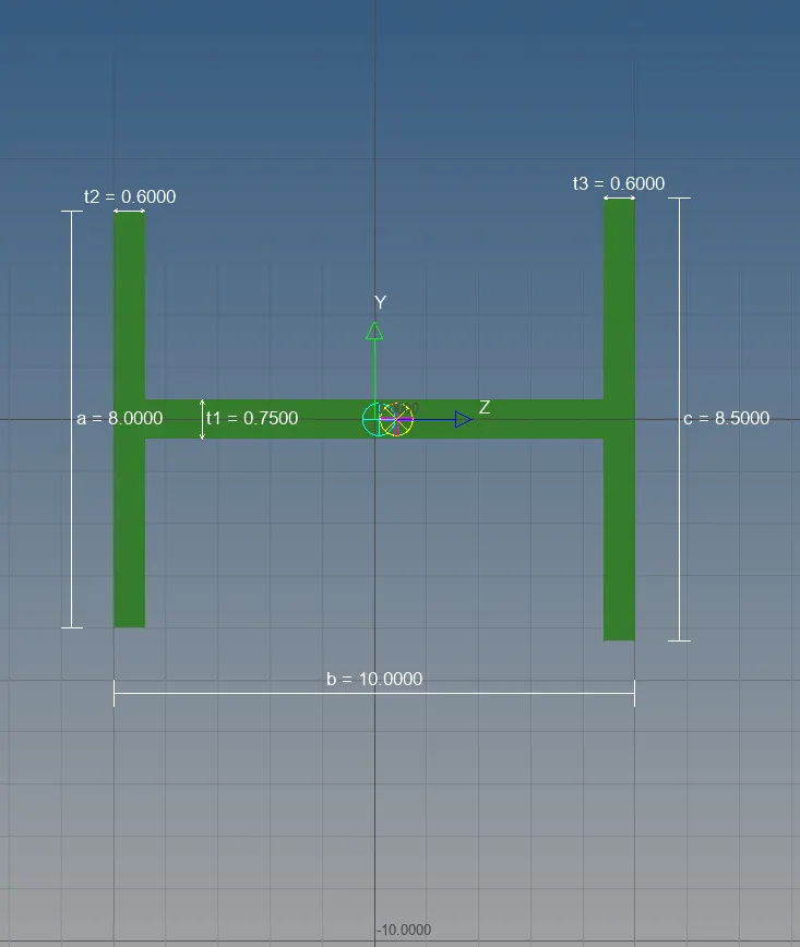
Cross-Section: I Section- Dimension a= 8 mm
Dimension b= 10 mm
Dimension c= 8.5 mm
Thickness t1= 0.75 mm
Thickness t2= .6 mm
Thickness t3= .6 mm
c. Bar element:- Constrain only x and y DOFs With RBE3 link
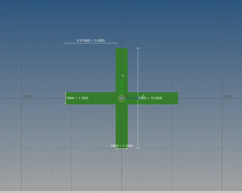
Cross-section: X section- Dimension DIM1= 5 mm
Thickness DIM2= 1.2 mm
Dimension DIM3= 10 mm
Thickness DIM4= 1.2mm
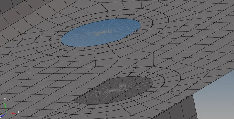
d. & e. Apply the mass of magnitude 10 with the RBE2 link
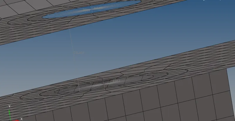
f. Join the two components with Spring elements.
---------------------------------------------------------------------------------------------------------------------------------------------------------------------------------------------------------------------
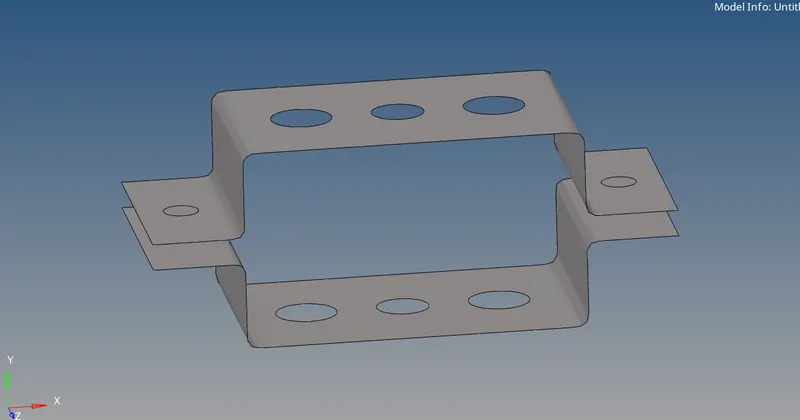
Creating mid surface:
Geom->Midsurface->Automidsurface->Select both the surfaces since they are of same property>Extract.
Assigning material to the component:
creating material
Create->material->name steel->card image MAT1
creating property
Create->property->Thickness t =3-> card image PSHELL ->material steel.
To assign this created property to the component, click on the component -> select the property, material will be automatically assigned to the component.
Let us consider both upper and lower bracket is made up of same material. i.e., steel.
Creating washer split:
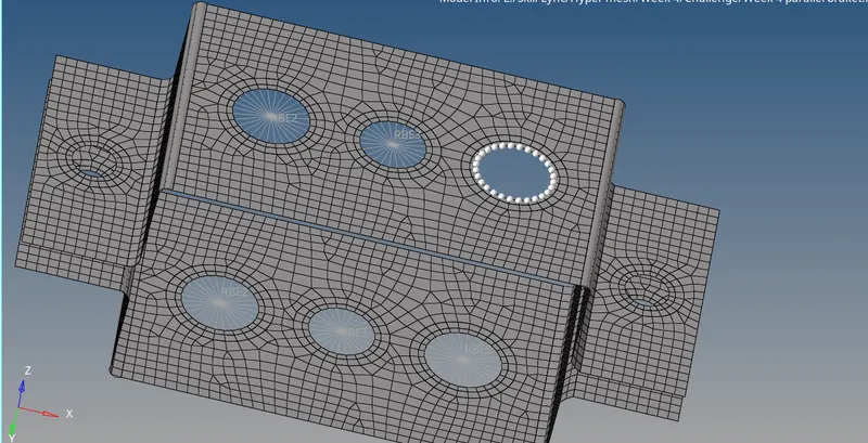
Geom> Quick edit> Washer splits with offset value of 7and 3.
Meshing
2D>automesh>select both the surface> Size 10->type mixed->mesh.
Creating 1D elements
RBE (Rigid body elements) are the most simple of 1D elements and simply connect two or more nodes together.
There are two types of RBE in htpermesh i.e., rbe2 and rbe3.
rbe2(rigid) one node serves as independent node and other(s) the dependent node(s). The dependent node is simply follow the motion of the independent node in the degrees of freedom that have been linked. rbe2 elements rigidly link nodes together. These elements are useful to simply represent Bolts or to tietogether two dissimilar meshes. One word of caution though is that rbe2 elements , as they rigidly link nodes together, can induce a stiffness to the model that may not be desired.
These elements will never bend, rotate, move.
rbe3 elements, serve to distribute loads without inducing unwanted stiffness. It is not a element to be used to model a connection, but rather an element to indice a motion a motion in a node as a function of weight average of other nodes.
These elements will move, bend,rotate.
Create rbe2 and rbe3 links. Which will have 1 independent node and cluster of elements.
rbe2 will have all of its trsnslation DOF's constrained i.e., dof1,dof2,dof3 checked.
1D> rigid>create>node (calculate node)->node (multiple node) and choose by path.
rbe3 for beam element will have all of its DOF's constrained i.e, both translation and rotation dof's.
rbe3 for bar element will have x and y DOF's constrained i.e., dof1, dof2, dof4, dof5 checked.
To assign different cross sections for the rod, beam and bar elements which will be created later, we first need do create box, I and X cross sections of required dimenssions.
Tool> hyperbeam>standard section library (hyper beam)-> standard section type (thinwalled box for rod element) create.
ones create is pressed we will be taken to hyperbeam section. Here we can create additional types of cross sections
for I section
Create> standard section> hypermesh> standard I section.
for X section
Create> standard section> optistruct> cross.
Go back to hyper mesh.
Before creating any element we need to assign the properties to the cross section which we just created.
For rod element
create> properties> card image PROD-> material steel -> in beam section choose the BOX cross section.
For beam element
create > properties > card image PBEAM-> material steel -> in beam section choose the I cross section.
For bar element
create > properties > card image PBAR-> material steel -> in beam section choose the X cross section.
Now,
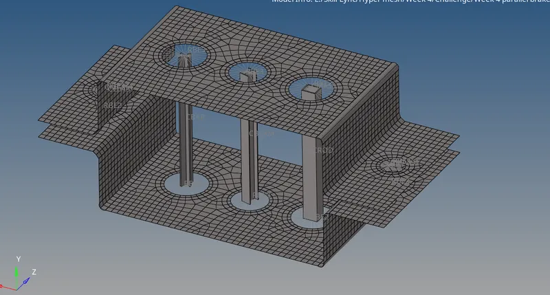
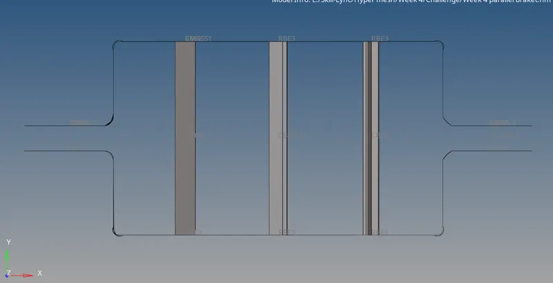
1D> rods > select two rbe2 independent nodes> assign property for rod element -> element type CROD.
1D> bars> select rbe3 independent nodes> assign property for beam element -> element type CBEAM.
1D> bars> select rbe3 independent nodes> assign property for bar element -> element type CBAR.
d & e
Apply the mass of magnitude 10 with the RBE2 link
First we need to create create rbe2 link. Next 1D> masses > select nodes on which load neads to be applied->element type CMASS1-> property bracket.
f
Join the two components with Spring elements.
1D > Springs>element type CELASI