Week - 4
AIM : To implement state flow logic control for automatic washing machine and automobile gear transmission system.
OBJECTIVE :
1. To create a simulink stateflow model of a fully automatic washing machine.
2.To create a simulink stateflow model to change the gear of car based in the speed of car.
PART I : AUTOMATIC WASHING MACHINE
Introduction :
A washing machine is a home appliance used to wash laundry. An automatic washing machine switches between different phase and does all the preocess starting from filling the water till drying the clothes.
The controller starts and stops many different processes including pumps and valves to fill and empty the drum with water, heating, and rotating at different speeds, with different combinations of settings for different fabrics.
Model Requirements:
If the power supply is available, the system gets activated
If the Water supply is not available, stop the process & indicate through LED
Soaking time should be 200s followed by Washing time of 100s.
Then rinsing happens for next 20s & dryer runs for 50s
After all the processes have completed turn on the finished LED
Simulink Model:
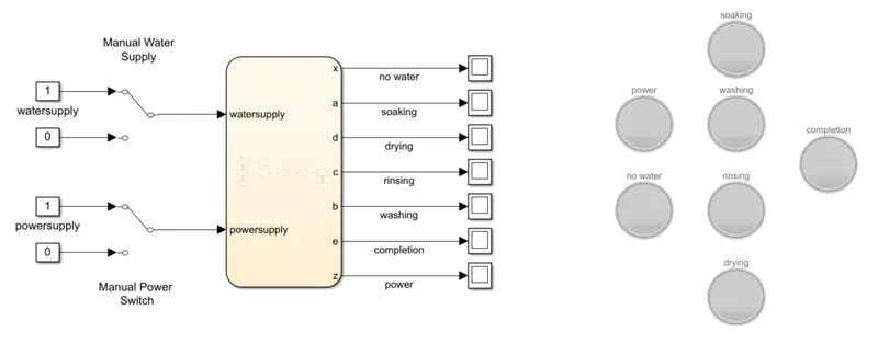
Blocks Used :
Constant : Output the constant specified by the 'Constant value' parameter.
Manuaal Switch : Output toggles between two inputs by double-clicking on the block.
Display : To display the current gear.
Chart : To create the stateflow logic.
Lamp : To indicate when the state(gear) is active.
Explaination :
As seen we have used two manual switches ,one for power supply and another for water supply.Value 1 is the ON state and value 0 is the OFF state.These two variables are the inputs for the stateflow chart.The stateflow logic will be explained further.
We are getting intotal 7 outputs from the state flow chart.One for the power supply ON OFF state.Other four are to check the state of the washing machine viz.soaking washing rinsing and drying respectively.Fifth output is for checking the completion of all processes.And the Final one is a warning signal if the water supply is ON or OFF.
All these outputs are connected to individual displays.And finally there are seven lamps for each of the mentioned outputs as well.
Stateflow Logic Model :
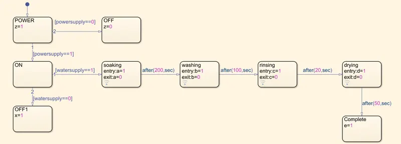
Explaination :
As we can see the first thing we are doing is checking the power supply.If the powersupply is not present then the system wont be activated.In reality the machine wont run only if the power is not present but for our programming sake we are adding this condition.
The next thing we are checking if the water supply is present.We need to first fill up the washing machine so that the clothes can soak in water.So if the watersupply is not present then the system will terminate.If the watersupply is ON the soaking process is activated and the clothes will soak for 200 seconds before moving on to the washing process.The clothes are washed for a period of 100 seconds then they are rinsed out.The water is drained out in the next 20 seconds.Our machine now is at drying statethe clothes are dried and the process continues for 50 seconds.
Finally the process is completed and the outputs from each of the state are given out from the chart.
Results :
1.We only run the code for 10 seconds to check whether the program runs if the power supply is OFF.
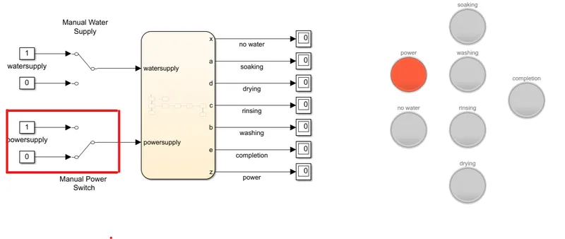
We can see that the power indicator turned RED.This indicates that the power is OFF and no processes are carried out.
2.Next we turn ON the powersupply but we still keep the watersupply OFF.
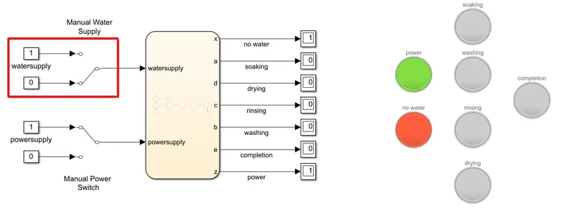
The green power lamp indicates that the power supply ids ON but the system is not working yet because our watersupply is OFF.We get a warning RED light of No water.
3.Now we turn ON both the watersupply and powersupply.The program itself takes some time to process the model ,apart from that we can know that the soaking will be carried on for the next 200 seconds.
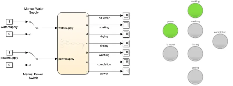
Running our program for 200 seconds shows that the soaking state is enabled.Soaking display shows value 1 and soaking lamp turns ON.
4.After this state the next state of washing is enabled.This process is carried out for the next 100 seconds.
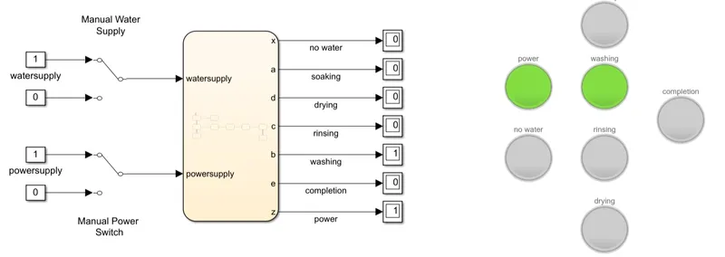
Running our program for 300 seconds shows that the washing state is enabled.Washing display shows value 1 and washing lamp turns ON.
5.After this state the next state of rinsing is enabled.This process is carried out for the next 20 seconds.
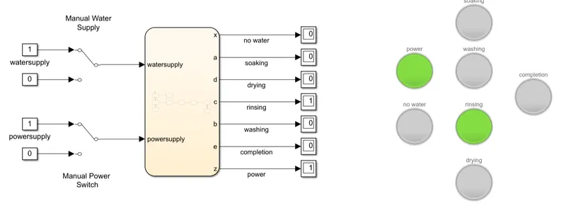
Running our program for 320 seconds shows that the washing state is enabled.Rinsing display shows value 1 and rinsing lamp turns ON.
6.After this state the next state of drying is enabled.This process is carried out for the next 50 seconds.
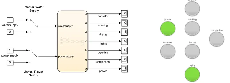
Running our program for 370 seconds shows that the washing state is enabled.Drying display shows value 1 and drying lamp turns ON.
7.Finally after waiting for 50 seconds drying will be completed and the last state will be activated.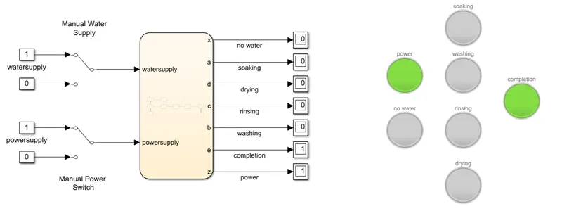
There are no further processes hence we can run the entire code for 400 seconds and see the completion lamp ON as well as completion display .
PART II: AUTOMATIC GEAR SHIFTER
Introduction :
An automatic transmission is multi-speed transmission used in automobiles that does not require any driver input to change gears under normal driving conditions.There are various types of transmission system but he basic principles is almost the same.
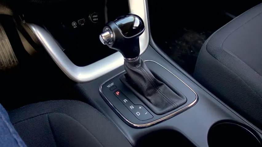
When we accelerate or decelerate the vehicles in drive mode, the speed of the car changes.There are sensors which detect the speed of the vehicle and based on the speed ,the system changes the gear of the system without user input.
Model Requirements:
| Speed Range(kmph) | Gear |
| 0 - 15 | 1 |
| 16 - 25 | 2 |
| 26 - 40 | 3 |
| 41 - 60 | 4 |
| Above 60 | 5 |
Simulink Model:
Blocks Used :
Constant : Output the constant specified by the 'Constant value' parameter.
Slider Gain : Move the slider to modify the scalar gain.
Scope : To display the output of speed vs gear change.
Display : To display the current gear.
Chart : To create the stateflow logic.
Circular Guage : We use at as rev counter.
Lamp : To indicate when the state(gear) is active.
Explaination :
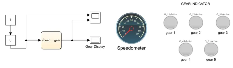
We use a slider to input our speed condition by setting the lower limit as 0 and upper limit as 100.This speed input is passed as the input to the stateflow chart.We will see the state flow logic ahead.When the logic is completed the system determines in which gear the car should be.Whatever the gear is selected it is given as the output.This gear is displayed in the display box.To see the changes in the input and output we use a scope block.
We have used a circular guage and used it as a speedmeter for better visualization of input speed.Further more we use 5 individual lamps to see which gear is engaged.The lamp is set to turn green when the particular gear is active.
Stateflow Logic Model :
Explaination :
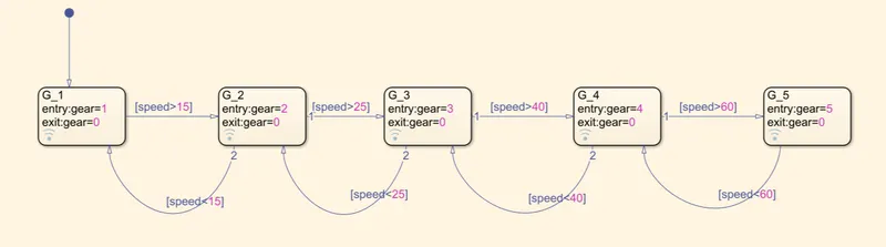
Speed is the input coming in the chart.Gear is the output.
Acceleration criteria:Speed is inputed to the G_1 state block and checked for the condition whether the speed>15,if false then the gear=1 is given as the output.If true then the state changes to G_2.Similarly the condition is checked if speed>25,if false then gear=2 is given as output.If true then the state changes to G_3.Input speed is checked if speed>40,if false gear=3 is given as output and if true the state changes to G_4.Again Input speed is checked if speed>60,if false gear=4 is given as output and if true the state changes to G_5 and gear=5 is given as output.
Deceleration criteria: The way we saw for acceleration the same follows for deceleration.Assuming we are already in 5th gear and the speed decrease below 60 then the state changes to G_4.If the speed changes and decreases below 40 then state G_3 is active.When speed comes below 25kmph then gear=2 is outputted and state G_2 is active.Finally if the speed falls down below 15kmph then first gear is selected.
We can see that each state has a exit value of 0.This is done because we want the lamp to switch off when the state is changed else the lamp will continue to lighutp once it si lit.
Results :
1.Graph for the gear change vs the speed input.
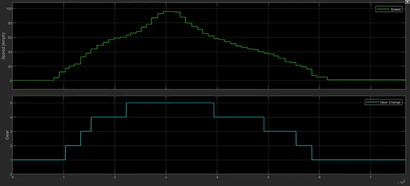
We randomly changed the speed between 0 kmph and 100 kmph to simply see the gear changes happening.
2.When the speed is between 0 and 15 kmph
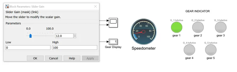
We can see that when the speed is 12kmph ,gear 1 is engaged.
3.When the speed is between 16 and 25 kmph
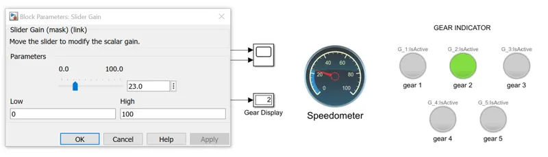
We can see that when the speed is 23 kmph ,gear 2 is engaged.
4.When the speed is between 25 and 40 kmph
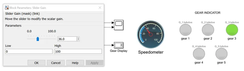
We can see that when the speed is 36 kmph ,gear 3 is engaged.
5.When the speed is between 40 and 60 kmph
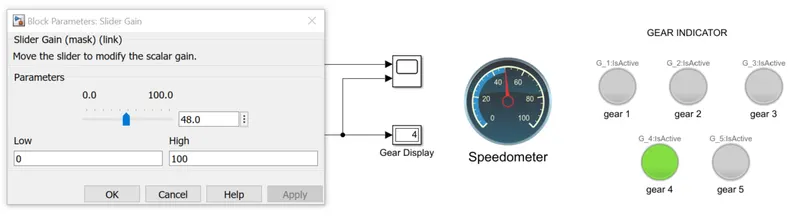
We can see that when the speed is 48 kmph ,gear 4 is engaged.
5.When the speed is above 60 kmph
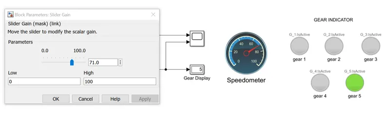
We can see that when the speed is above 60 kmph,gear 5 is engaged.
CONCLUSION :
We have successfully created a washing machine model which carries out all the processes and signals when the process is completed.Also the system only runs when the power supply is switched on and if the water supply is not present we get a warning.
We were able to created a simulink model of automatic gear shifting system.
REFERENCE :
YOUTUBE:
1.Getting started with stateflow
https://www.youtube.com/watch?v=XpQ2osUE4v4
2.Basic simulink stateflow tutorial
https://www.youtube.com/watch?v=wRNbvW9tTZQ
3.Control logic made easy with stateflow