Week -2
AIM :
To create and study Simulink model of a Doorbell and a Thermistor controlled Fan.
OBJECTIVE :
1.To simulate a situation where the circuit is closed for 2 seconds and we need to observe the plunger movement which would be attached to the solenoid.
2.To simulate a thermistor model to sense the temperature of a heater & turn on or turn off the fan as per required conditions.
PART I : DOORBELL SIMULATION
Theory :
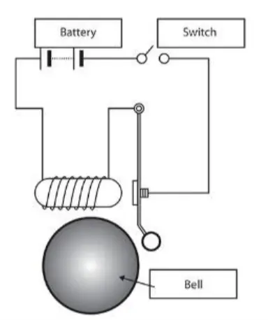
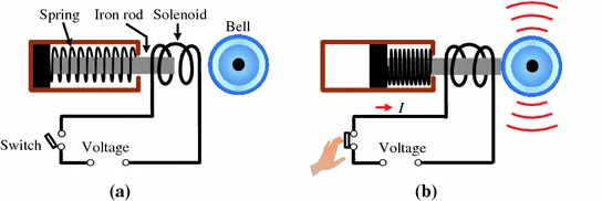
A chime doorbell uses a specialized sort of electromagnet called a solenoid. A solenoid is just an electromagnet where the coiled wire surrounds a metal plunger. The plunger contains magnetically conductive metal, so it can be moved backward or forward by the electromagnetic field.When the circuit is closed,magnetic field is created and this pulnger then moves to hit the gong creating the sound.
Model Requirement :
Create a situation where the switch is closed for 2 seconds and then released.
Observe the physical movement of the plunger.
Simulink Model:
Blocks used :
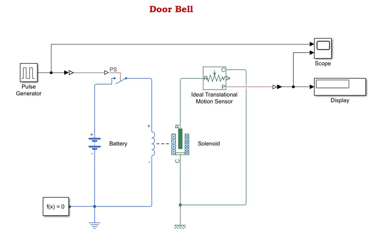
1.Pulse Generator. Generate signal as per the requirement.
2.Battery. To supply electrical energy.
3.Simulink to Ps Converter. Convert simulink signal to Physical signal
4.PS toSimulink Converter. Convert physical signal to Simulink signal.
5.Solver Configuration. Defines solver settings to use for simulation.
6.Solenoid. This block implements the electrical and mechanical characteristics of a solenoid.
7.Ideal Translational Motion Sensor. To monitor the plunger displacement.
8.Scope. To see the pulse wave and the corresponding displacement of plunger wrt time.
9.Display.This block will show the final displacement of the solenoid attached plunger.
10.Refernce. Electrical and Mechanical translation reference blocks are used.
Model Explaination.
Starting from the pulse generator we create a pulse wave having of amplitude 1, 4 sec timeperiod and a pulse width of 50%(2 sec).This is connected to a switch through a simulink ps converter.The switch is set to close the circuit when the signal goes above 0.5.So our circuit would be close for 2 seconds of the 4 seconds timeperiod.
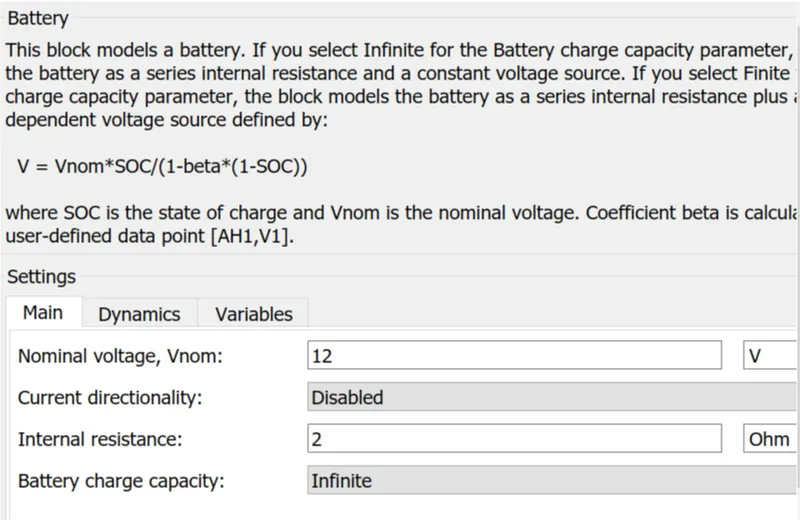
We insert a Solenoid and complete the circuit by connecting a battery(12V).The remaining R and C ports are still disconnect at this point.We know that R moves wrt C when energy is supplied.We have to assume that this R port is connected to a plunger in reality which in return will ring the gong/bell.So to observe that movement we connect a ideal translational motion sensor between R and C.The port P of this sensor shows the displacment so we connect this port to a display and a scope.For better visualization we also connect the starting pulse generator to the scope as well.
In order to simulate the module we attach a solver configuration to the circuit and to finish off the circuit we provide the electrical and translation motion refernces.
Results :
Case I:
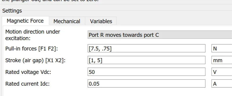
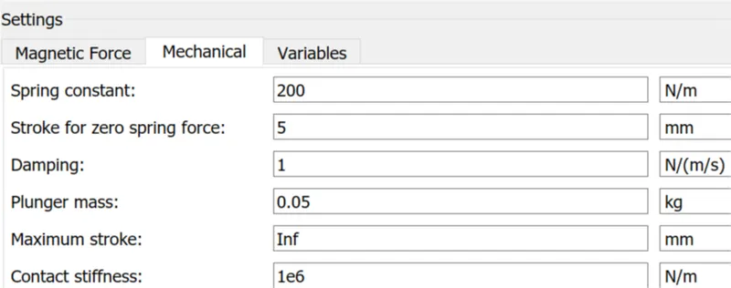
In case I we kept the battery and the solenoid magnetic as well as mechanical parameters as default.Following are the results obtained when we run our simulation for 20 seconds.
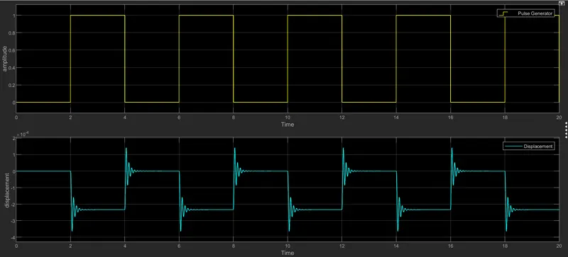
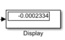
We can see the input signal is given for 2 seconds from a time period of 4 seconds. We can observe the displacement of plunger as well.We are getting the displacement but we can see that there is ripple effect.We need to smooth down these these vibrations.
Also we can see from the parameter block that the gap is of 5mm yet we are gettting very less displacement.
Case II:
Our solenoid is rated for 50V and in our default settings we provided only 12V.Now we change our battery settings to 30V.
And in order to lower the vibrations we need to lower the spring constant and increase the damping coefficient.
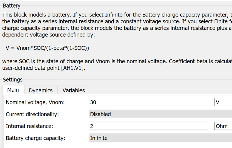
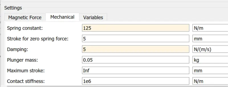
Applying the above changes and we get the following result.
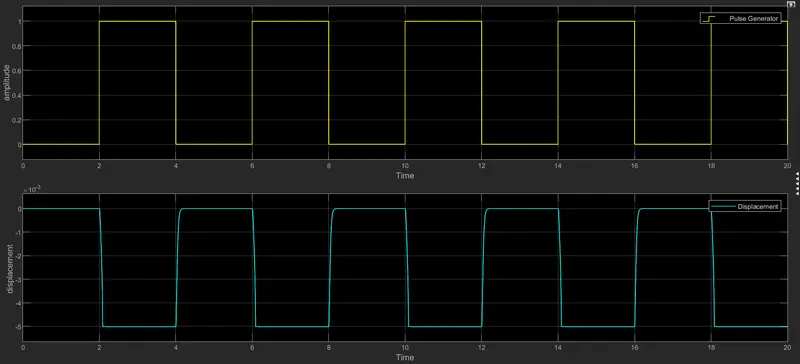
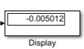
We can see that we are getting a displacement of 5 mm and also the plunger returns to its equilibrium position when signal is removed.Also the vibrations are smoothend out.
PART II :TEMPERATURE CONTROLLED FAN USING THERMISTOR
Theory :
A thermistor is a resistance thermometer, or a resistor whose resistance is dependent on temperature. The term is a combination of “thermal” and “resistor”.
Reference Figure
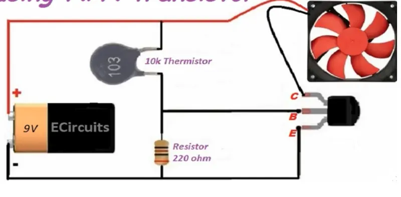
We have to make a circuit which uses a thermistor and the fan needs to be operating only when the temperature reaches a certain point.An automatic circuit can be made if the fan cooling is used to cool the thermistor.This way when the thermistor heats up its resistance would decrease this would allow the current flow to fan an then fan will start.This fan will run until the thermistor is cooled down to specified temperature.
Model Requirement :
Temperature source: 20 °C from 0 to 10 seconds, 27 °C from 10 to 30 seconds, 23 °C from 30 to 50 seconds
Fan conditions: ON if the temperature above 25 °C, OFF otherwise.
Simulink Model :
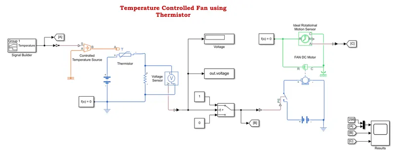
Blocks Used :
1.Signal Builder. To create a siganl wave.
2.Goto.To send output from one part to another.
3.From.To recieve signal/output sent from another part.
4.Controlled Temperature Source. Maintain controlled temperature difference regardless of the heat flow rate.
5.Battery. To supply electrical energy.
6.Simulink to Ps Converter. Convert simulink signal to Physical signal
7.PS toSimulink Converter. Convert physical signal to Simulink signal.
8.Solver Configuration. Defines solver settings to use for simulation.
9.Scope. To see the pulse wave and the corresponding displacement of plunger wrt time.
10.Display.This block will show the voltage around the refernce resistor.
11.Refernce. Electrical and Mechanical Rotational reference blocks are used.
12.Thermistor. This represents an NTC thermistor whose resistance decrease with increase in temperature.
13.Resistor. A reference resistor is used to measure the volatage around this resistor.
14.Voltage sensor. To measure voltage across the reference resistor in the circuit.
15.Switch.Closes the circut when input is above certain threshold value.
16.Switch case. Pass through input 1 when input 2 satisfies the selected criterion; otherwise, pass through input 3.
17.Constant.Contains a fixed value.
18.Mux. Merges signals.
19.DC Motor. This block represents the electrical and torque characteristics of a DC motor.
20.Ideal Rotational Motion Sensor. This block measures angular velocity or angle in a mechanical rotational network.
Model Explaination.
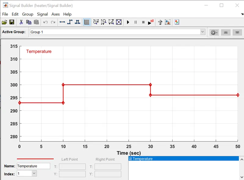
As per our requirement we need 20 °C from 0 to 10 seconds, 27 °C from 10 to 30 seconds, 23 °C from 30 to 50 seconds.We convert the temperature to kelvin and modify the signal builder accordingly as shown
We provide this signal to the variable temperature control souce which then passes this temperature signals to the thermistor.The themistor also has its resistance but we also attach a refernce resistor of 1 ohm in series with the thermistor.we can measure either the current flow or temperature flow around this resistor which we will be needing for the switch case condition.
We run the simulation with this much model build and pass the voltage output to the workspace.
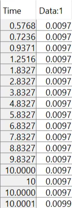
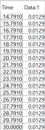
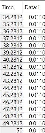
As we can see when the temperature is 293K the voltage around the resistor is 0.0097V,at 300K is 0.0129V and at 296K is 0.0110V. This can be set as the threshold value for the switch case.i.e when the voltage is above 0.0110V then the unit signal is passed and if not then the 0 value is passed.
This signal is passed to a switch which closes the circuit when the signal is 1 and opens the circuit when the signal is 0.There is no mechanical fan block present in simulink so we use a dc motor which resembles the fan motor.To see if the fan works we use a ideal rotational motion sensor to observe the fan displacement.
Finally we send the temperature signals, switch case signal and the rotational motion sensor signal to the scope to observe the results.For sending and recieving signals we use from and goto block.
Results:
Graph 1:
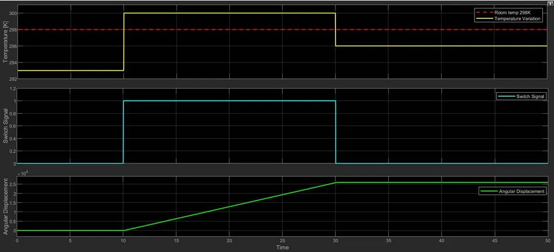
From 0 to 10 s the temperature is 293K .From 10 to 30s it is 300K and for the last 20 seconds it is 296K. For reference a line of 298K is also added.
Graph 2:
We can see that when the temperature is below 298K i.e from 10s to 30s we get a unit signal and for the rest of time we have no signal or 0.
Graph 3:
From 0 to 10 seconds the fan is off as seen because the temperature is below 298K.When temperature rises above 298K we can see the fan rotates till 30s.When the temperature falls for the next 20s the fan stops rotating.
ERRORS FACED :
1.In our heater model we have two separate physical networks ; one on the thermistor side and other on the fan(dc motor) side.We need to connect a separate solver for both of them.I connected only one solver for the entire system hence the error.

The error was easily solved by using two seperate solvers for both seperate systems.
2.This error occured in the simulink to PS converter block.
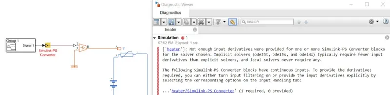
This error was rectified by using input filtering and providing input derivative in the Simulink PS block properties.
CONCLUSION :
1.We can see that the plunger moves and the bell rings for every 2 seconds then stops; the loop continues till the model runs.
2.We can also see that the fan rotates when the temperature rises above 298K (25 C).
REFERENCE :
Youtube:
Thermistor controlled fan
https://www.youtube.com/watch?v=9opuvLXAetI
Mathwork
Inbuilt Simulink Model For better understanding
https://in.mathworks.com/help/physmod/sps/ug/thermistor-controlled-fan.html
Doorbell working
https://home.howstuffworks.com/home-improvement/repair/doorbell3.htm