Week 4.1: Project Steady state simulation of flow over a throttle body
OBJECTIVE:
We will be performing a stead-state simulation over a throttle body in an elbow and document our observations with velocity and pressure contours.
GEOMETRY:
The following geometry is used for simulation:
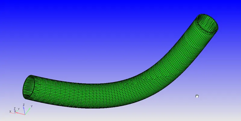
The geometry has some thickness to it so we will be removing the outer shell and the edges which creates the open edges:
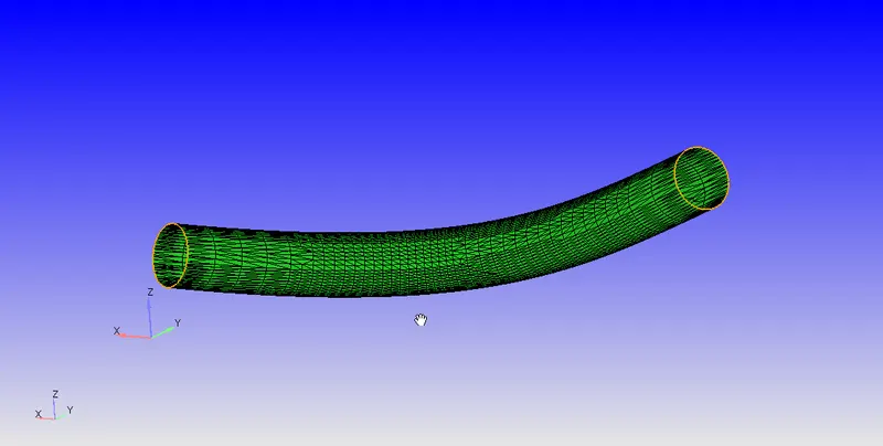
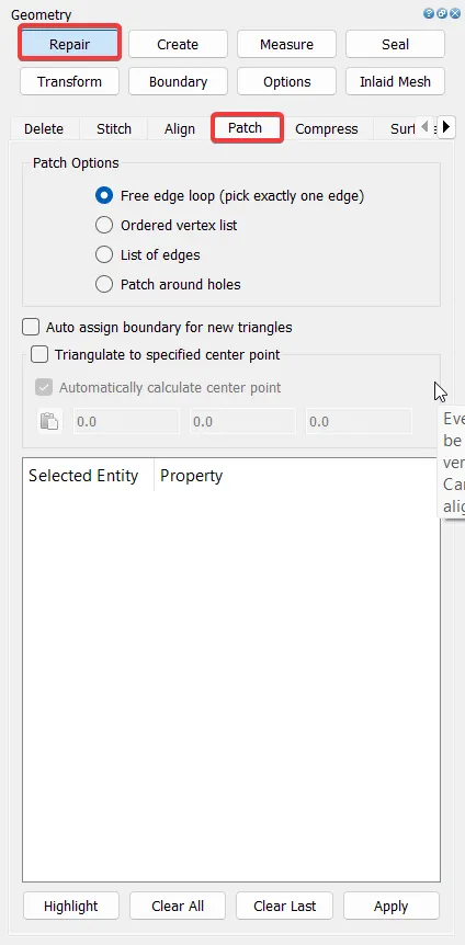
We then use the patch tool to patch these open edges:
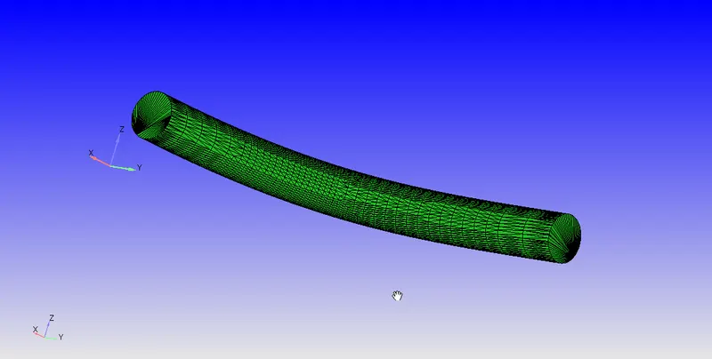
Patched Geometry:
BOUNDARY FLAGGING:
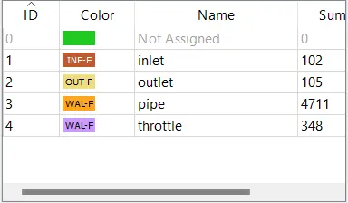
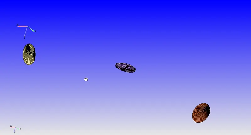
Inlet, outlet and Throttle:
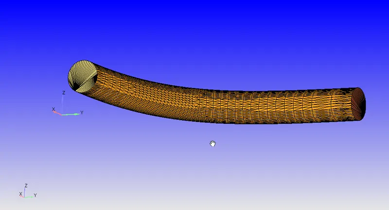
Pipe Wall:
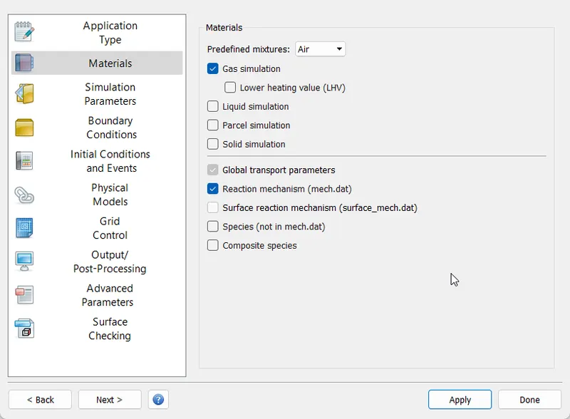
CASE SETUP:
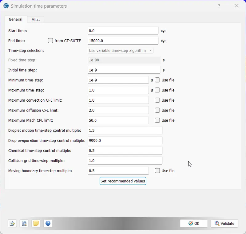
Simulation Parameters:
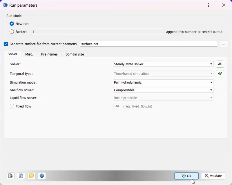
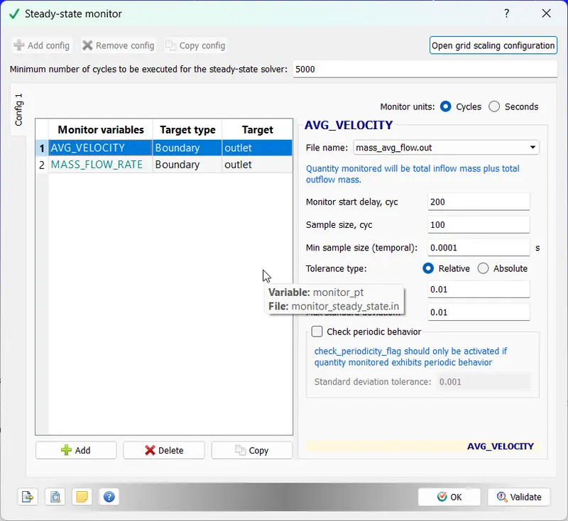
We are using steady-state pressure based solver:
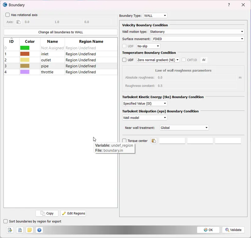
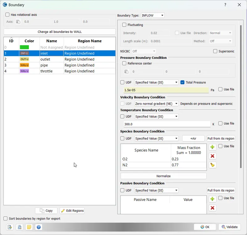
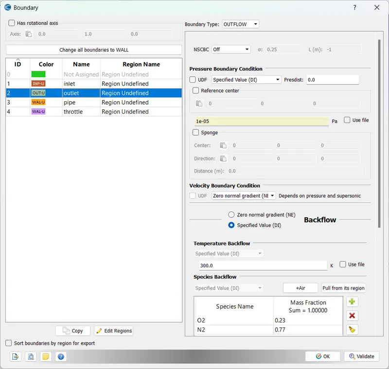
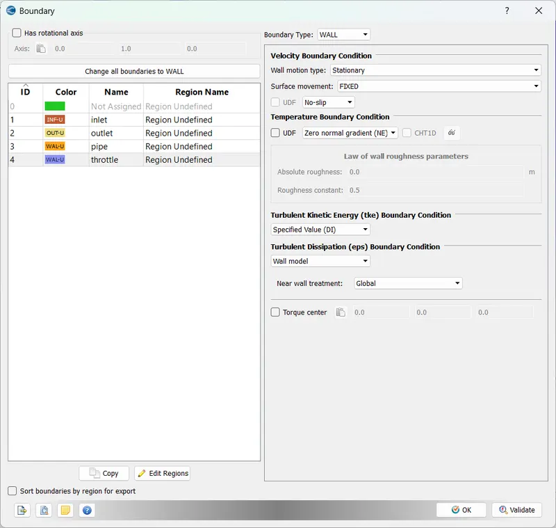
Boundary Conditions:
MESHING:
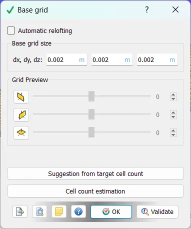
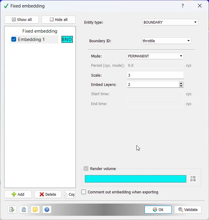
We use fixed embedding to improvise the mesh near the throttle:
RESULTS:
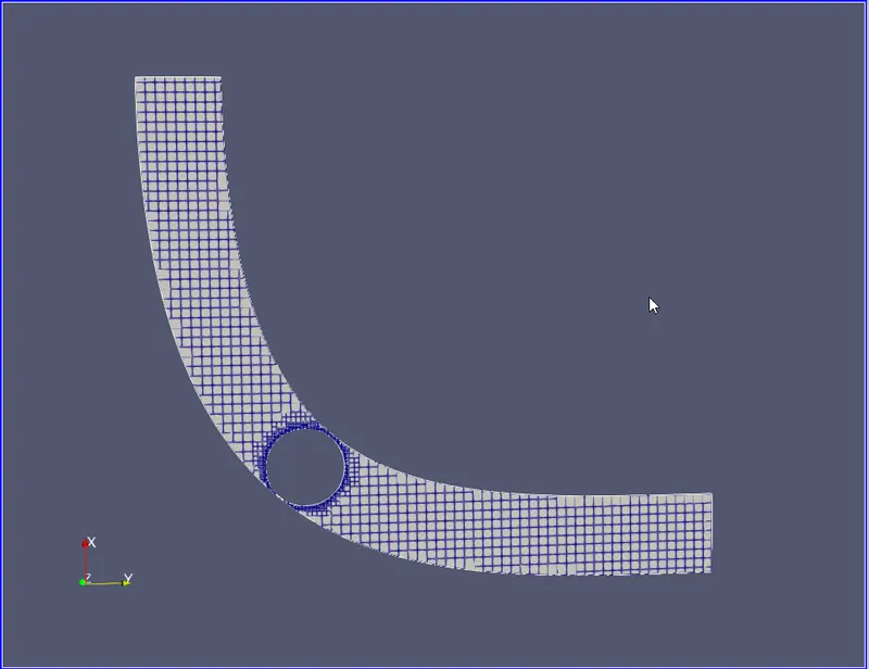
MESH:
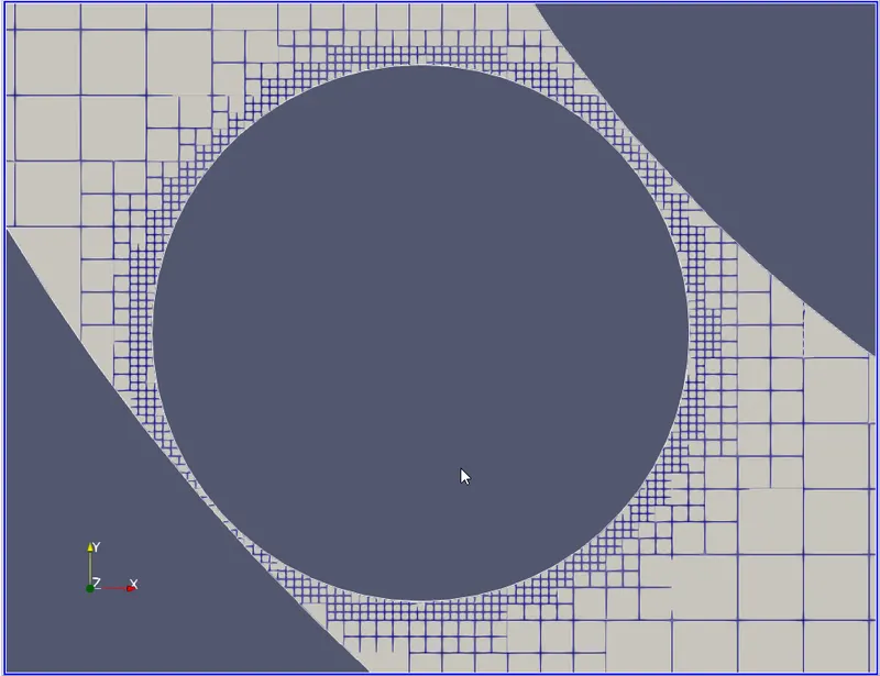
Throttle Close Up:
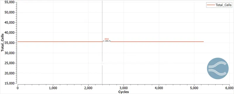
CELL COUNT:
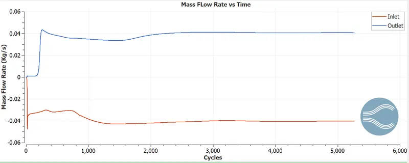
MASS FLOW RATE:
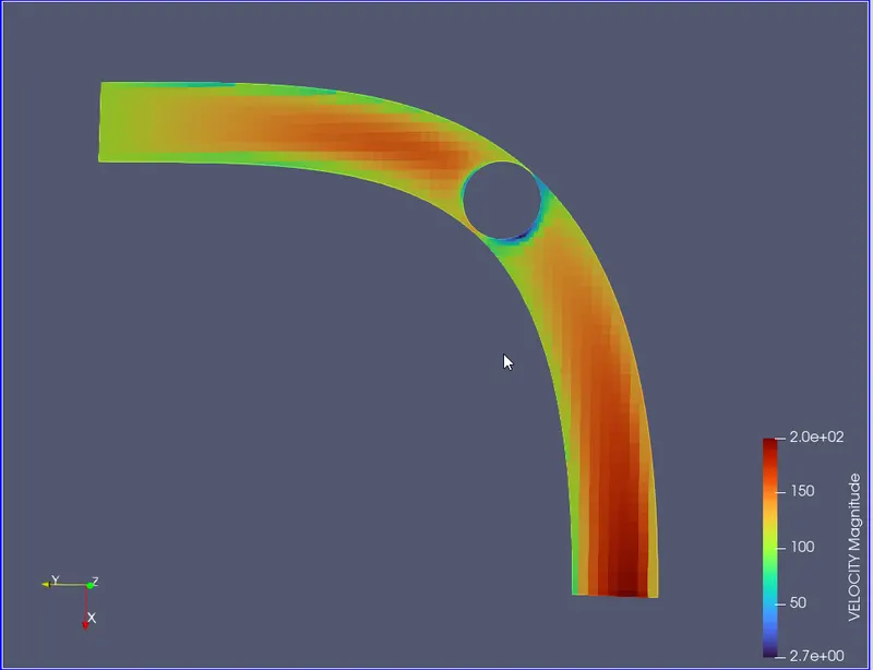
VELOCITY CONTOUR:
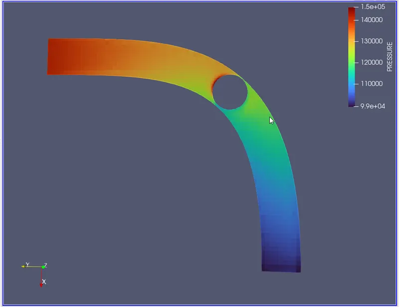
PRESSURE CONTOUR:
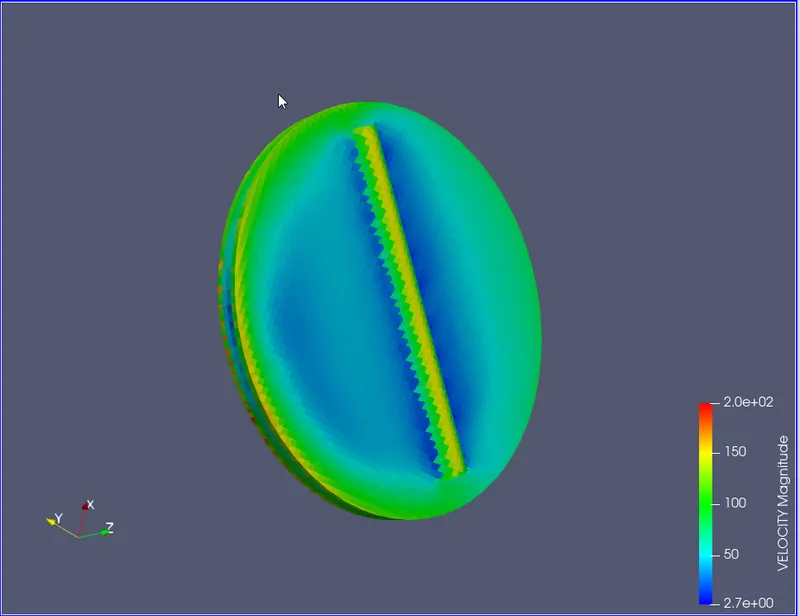
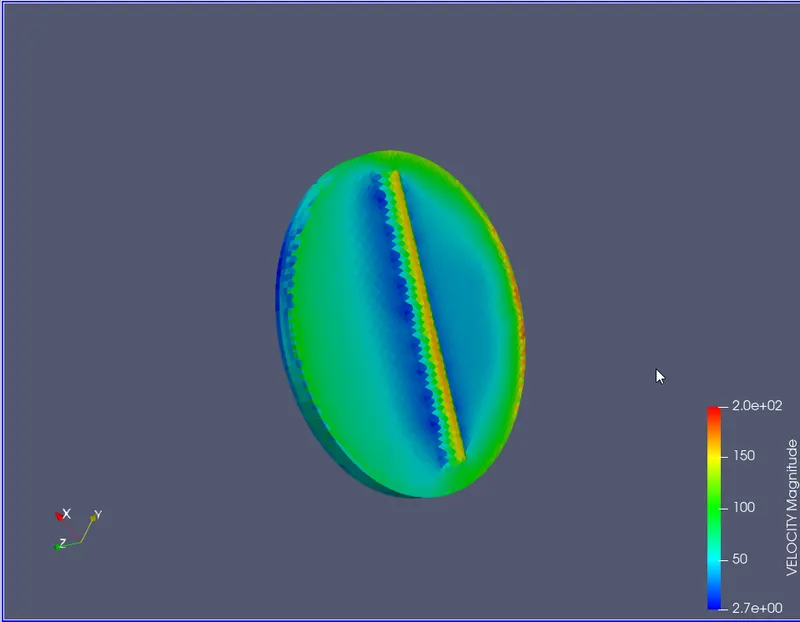
VELOCITY CONTOUR (THROTTLE):
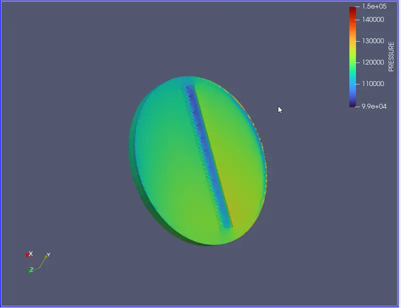
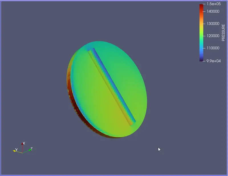
PRESSURE CONTOUR (THROTTLE):
CONCLUSION:
- As the flow encounters the throttle, it moves around the throttle which causes a decrease in mass flow rate as depicted in the chart. The inlet mass flow rate increases while the outlet mass flows rate remains stagnant.
- The throttle clearly divides the elbow into a region of low pressure and high pressure as seen from the contours on the throttle as well as the pressure contours on the complete body.