Verification of Weld Joints using Ansys
INTRODUCTION
In this work, a bracket model joined using welds was used to check the variation in the maximum directional deformation, equivalent strain, and stress, when the material of the weld nugget was changed according to the following three cases.
Case 1: In this case, the material of the plates and welds was stainless steel.
Case 2: In this case, the material of the weld nuggets was aluminum alloy (high strength, wrought). The material of the plates and ribs was stainless steel.
Case 3: In this case, the material of weld nuggets was bronze and the material of ribs was copper.
OBJECTIVE
- To assign the material to the parts, according to the case.
- To assign the contacts.
- To mesh the model.
- To apply the boundary condition.
- To collect the results and interpret.
PROCEDURE
The simulation seems to be static non-linear, therefore, it had to solve using the Static Structural module of Ansys. The bracket model is shown in the figure below. Next, the material had to define before proceeding further. Using Engineering data, all the required materials viz. structural steel, high strength wrought aluminum, copper, and cast bronze were imported.
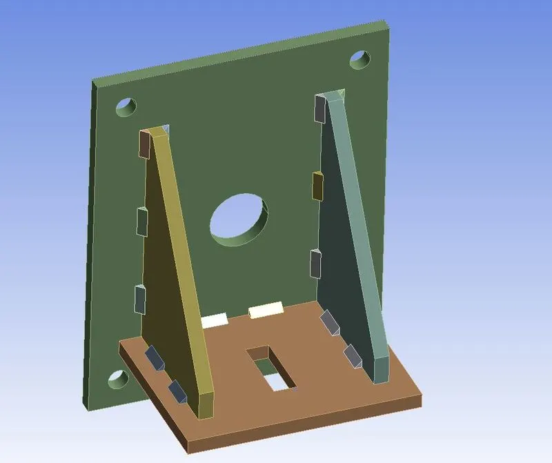
Figure 1: Bracket model in Ansys GUI.
The Mesh section of the Static Structural module was opened. In that, for the first case, the material of all the parts in the model was changed to structural steel.
Further, the Ansys already detected the contact regions, and therefore default bonded contact was created. The automatically created contact cards were kept as it is, for the faces of the weld nuggets and their neighboring faces, while for the faces of plates in contact, their contact behavior was changed to friction with a coefficient of friction of 0.2.
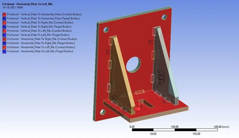
Figure 2: Frictional contact set between the plates.
After contact, the model had to mesh. For meshing, the element size for plats was set to 7 mm, and for ribs, it was set to 10 mm.
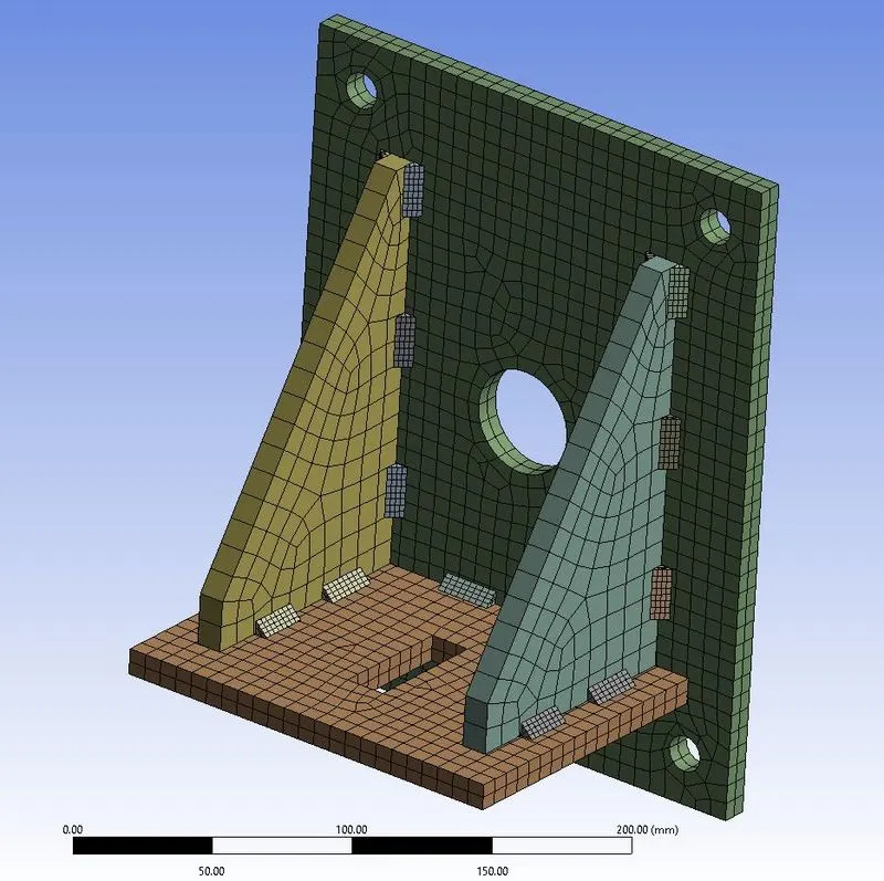
Figure 3: Meshing of the model.
One plate in the model has five circular holes in it. In boundary conditions, that plate was fixed, as shown in the figure below.
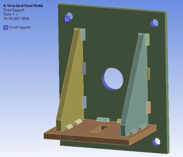
Figure 4: One plate is fixed with holes.
To the other horizontal plate, a force of 15000 N was applied on the rectangular hole, in the vertically downward direction, as shown in the figure below.
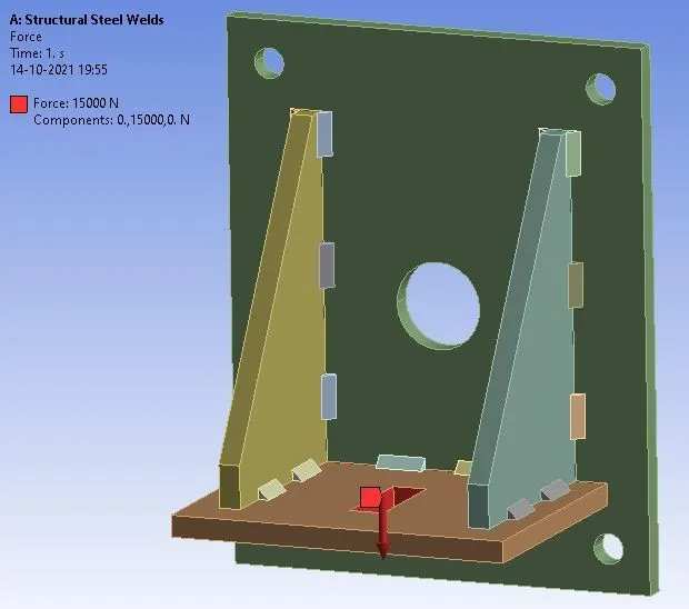
Figure 5: A vertically downward force of 15000 N on the other plate.
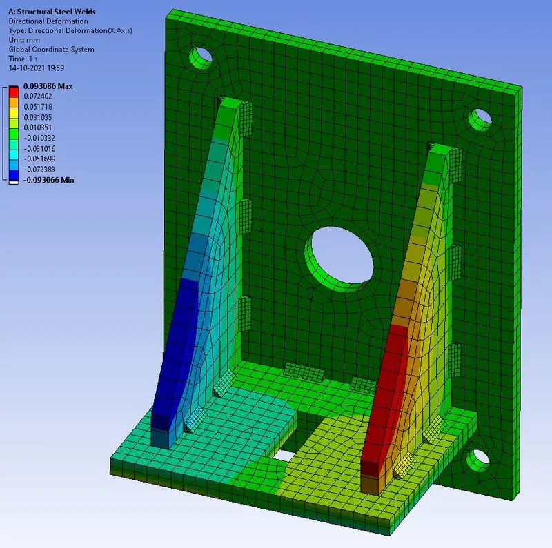
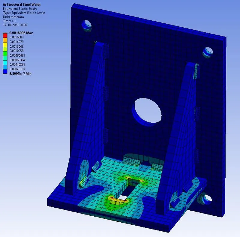
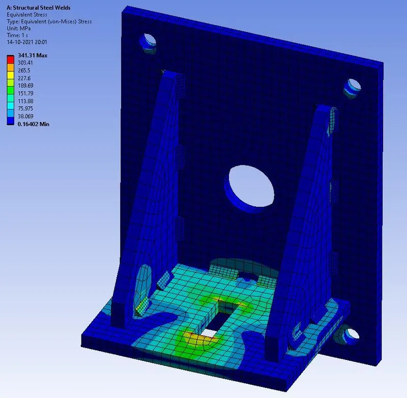
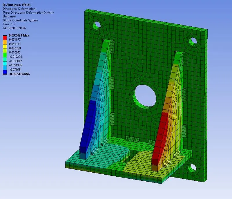
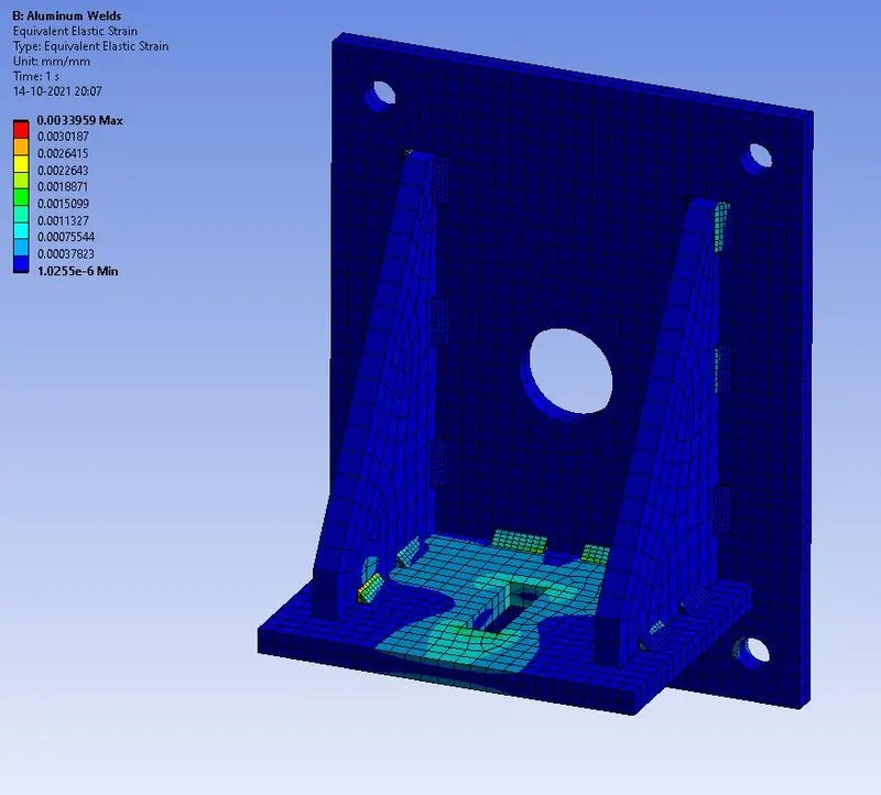
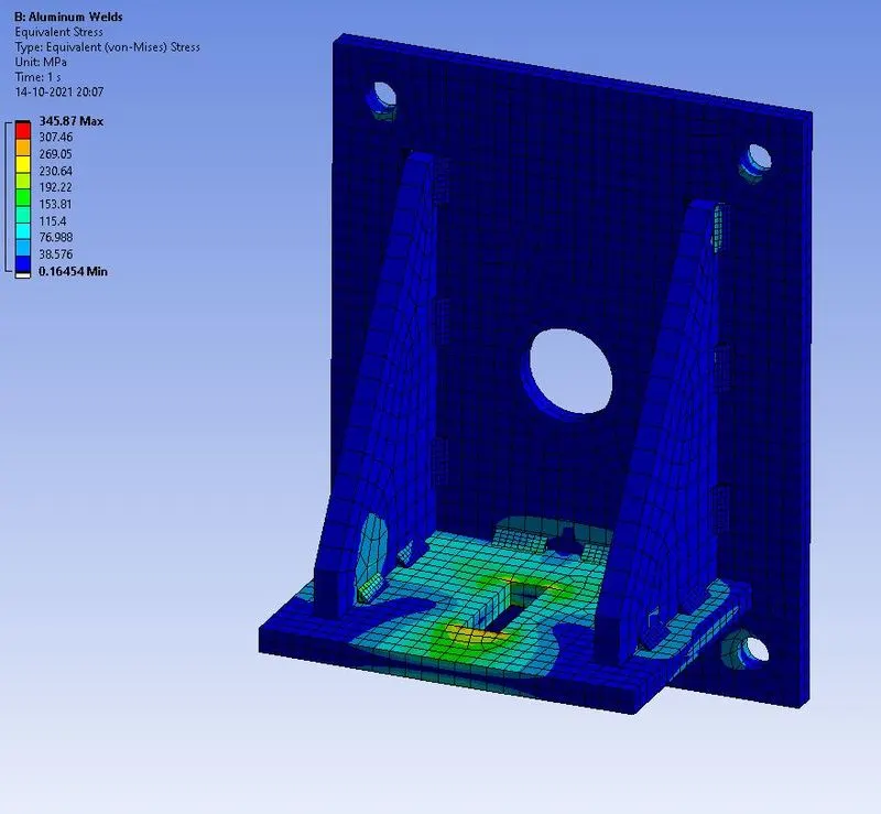
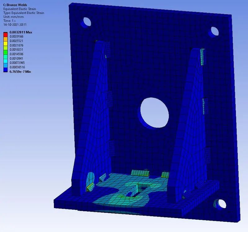
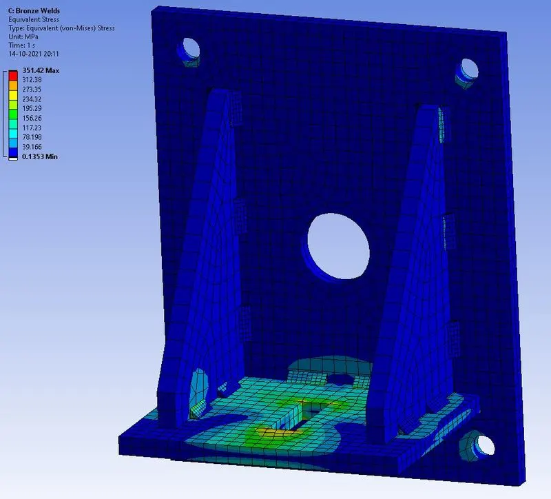
In the solution, the results for directional deformation, equivalent strain, and equivalent stress were requested. The results of each case are shown in the figures below.
 |
 |
 |
|
Directional Deformation |
Equivalent Strain |
Equivalent Stress |
|
Figure 6: Results for case 1, when the material of all the parts was structural steel. |
||
 |
 |
 |
|
Directional Deformation |
Equivalent Strain |
Equivalent Stress |
|
Figure 7: Results for case 2, when the material of the weld nuggets was aluminum, and the material of all the plates was structural steel. |
||
 |
 |
 |
|
Directional Deformation |
Equivalent Strain |
Equivalent Stress |
|
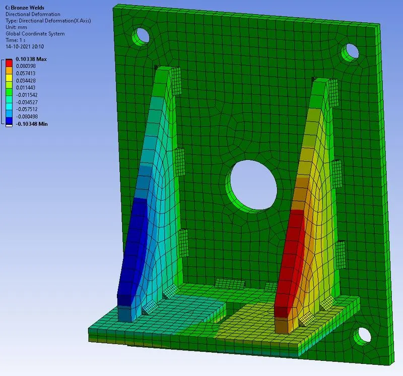
Figure 8: Results for case 3, when the material of the weld nuggets was bronze, the material of the ribs was copper, and the material of the horizontal and vertical plates was structural steel. |
||
In the third case, the maximum deformation occurred at the right rib of 0.10338 MPa, which is comparably very high to the other two cases. The least elastic strain in the three cases can be observed in the first case, followed by the third case. In the first case, the maximum elastic strain of 0.0018 mm/mm occurred, and that too at the rectangular hole region. In the other two cases, the maximum elastic strain occurred at the weld nuggets. Also, the least maximum, equivalent stress was also occurred in the first case, followed by the second case. This shows that the weld nugget with structural steel material is the better option to consider.