Verification of Weld Joints
AIM:
- To perform Static Structural analysis on weld using different materials and obtain the results.
OBJECTIVES OF THE PROJECT:
- To define material for the weld.
- To define contact faces for the weld.
- To define fixed support and apply force on the plate.
- To perform mesh on the plate, ribs and the welds.
- To define face sizing for fine meshing on the ribs.
- To evaluate the maximum stress, strain and deformation.
PROCEDURE:
- Case 1 -
- OPEN > WORKBENCH > NEW PROJECT > STATIC STRUCTURAL.
- This will define static structural project.
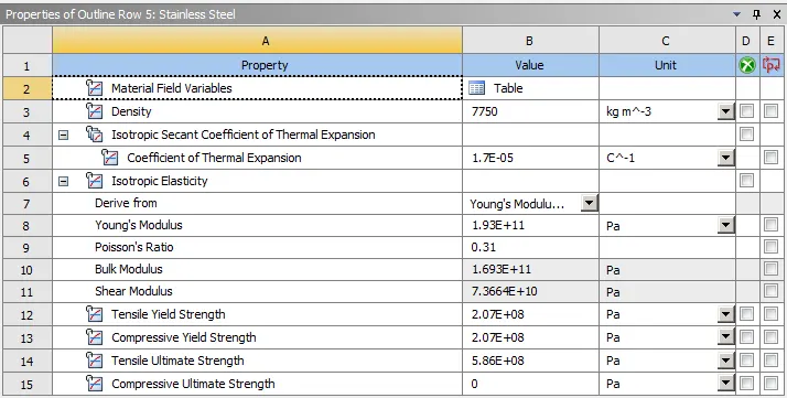
- Now, go to ENGINEERING DATA > EDIT > ADD > STAINLESS STEEL.
- Go to GEOMETRY > IMPORT > BROWSE > WELDING.STP.
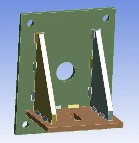
- This will import the welding geometry.
- Then, DOUBLE CLICK ON MODEL. This will open the mechanical module.
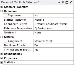
- Assign material as Stainless steel to all the components.
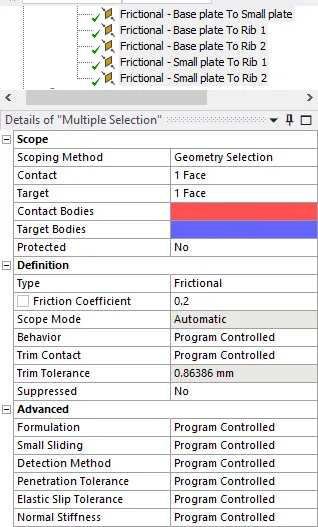
- Go to CONNECTIONS > CONTACTS > PLATE AND RIBS > TYPE > FRICTIONAL > FRICTION COEFFICIENT = 0.2.
- Now, go to MESH > ELEMENT SIZE = DEFAULT.
- MESH > INSERT > SIZING > ELEMENT SIZE = 7MM > SCOPE > RIBS > GENERATE MESH.
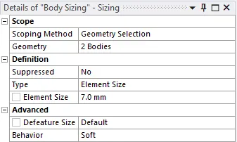
- This will create mesh on the geometry according to the element size.
- Now, go to STATIC STRUCTURAL > ANALYSIS SETTINGS > LARGE DEFLECTION = ON.
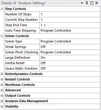
- Then, STATIC STRUCTURAL > INSERT > FIXED SUPPORT > SCOPE > ALL THE HOLES ON THE BASE PLATE.
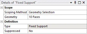
- Then, INSERT > FORCE > TYPE = COMPONENTS > Y = 15000N > SCOPE > THE SLOT FACES ON THE SMALL PLATE.
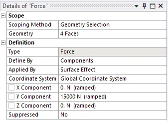
- Go to SOLUTION > INSERT > STRESS > STRAIN > DIRECTIONAL DEFORMATION.
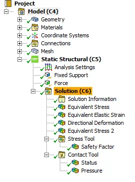
- Go to SOLUTION > SOLVE.
- Case 2 –
- For the second case, we have to assign Aluminium alloy as material for the weld and Stainless steel for the plate and ribs.
- NEW > STATIC STRUCTURAL > ALUMINIUM ALLOY.
- Now, go to ENGINEERING DATA > EDIT > ADD > STAINLESS STEEL and ALUMINIUM ALLOY.
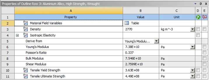
- Share the geometry from case 1.
- This will import the welding geometry.
- Then, DOUBLE CLICK ON MODEL. This will open the mechanical module.
- Assign material as Stainless steel to the plate and rib components and assign Aluminium alloy to the welds.
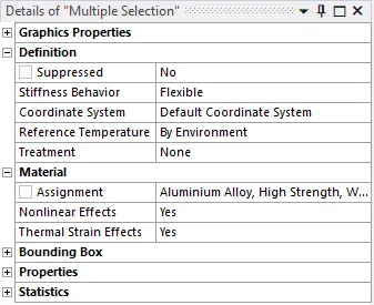
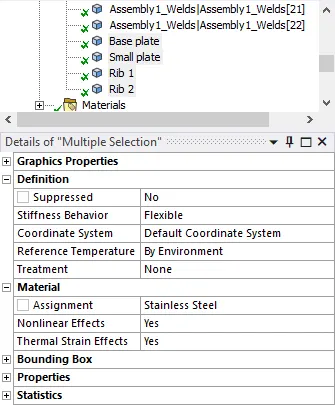
- Then repeats the steps as in case 1 and solve the model for Aluminium alloy.
- Case 3:
- For the third case, we have to assign Bronze as material for the weld and Stainless steel to the plates and Copper to the ribs.
- NEW > STATIC STRUCTURAL > BRONZE.
- Now, go to ENGINEERING DATA > EDIT > ADD > STAINLESS STEEL, BRONZE and COPPER ALLOY.
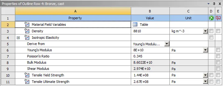
- Share the geometry from case 2.
- This will import the welding geometry.
- Then, DOUBLE CLICK ON MODEL. This will open the mechanical module.
- Assign material as Stainless steel to the plates and copper alloy to ribs and Bronze to the welds.
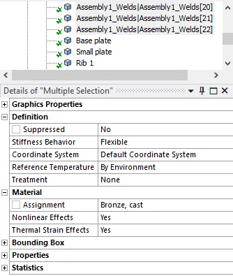
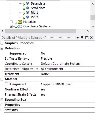
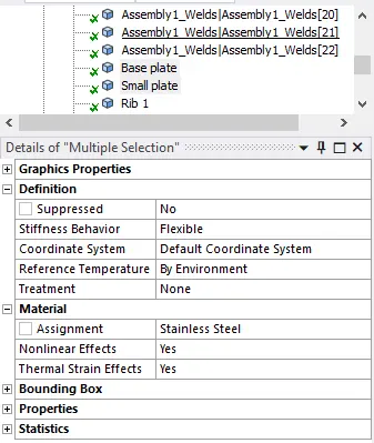
- Then repeats the steps as in case 1 and solve the model for Aluminium alloy.
RESULTS:
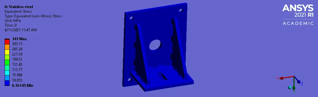
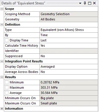
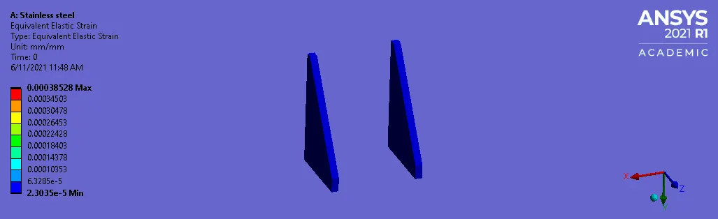
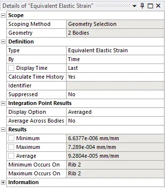
- Case 1 -
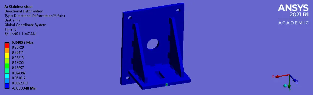
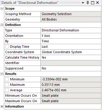
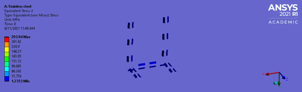
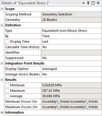
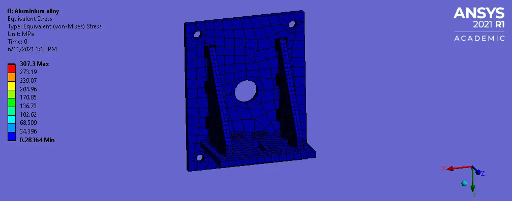
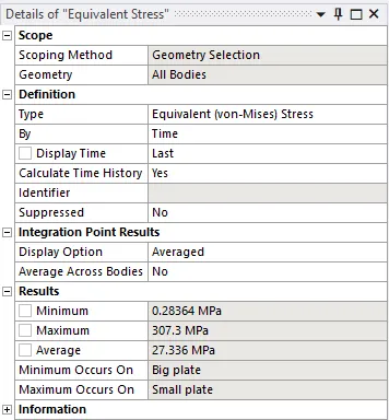
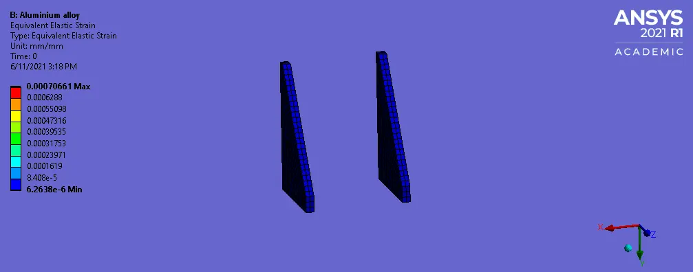
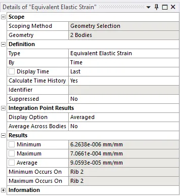
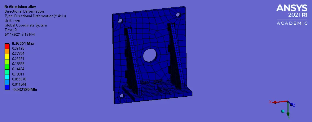
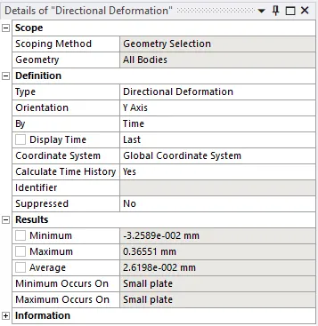
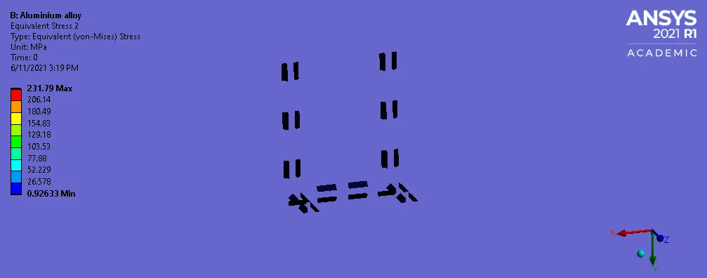
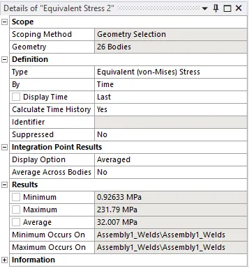
- Case 2 -
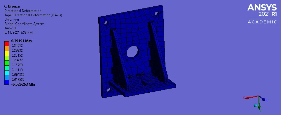
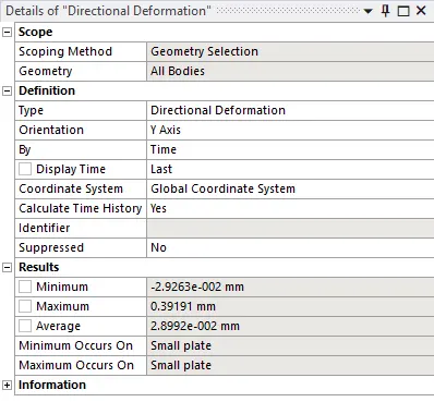
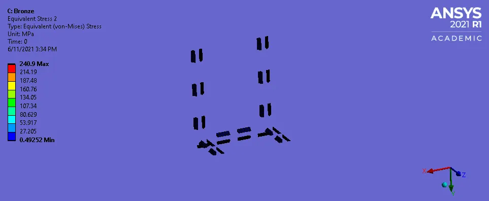
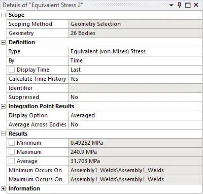
- Case 3 -
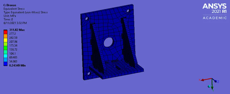
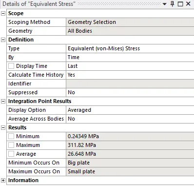
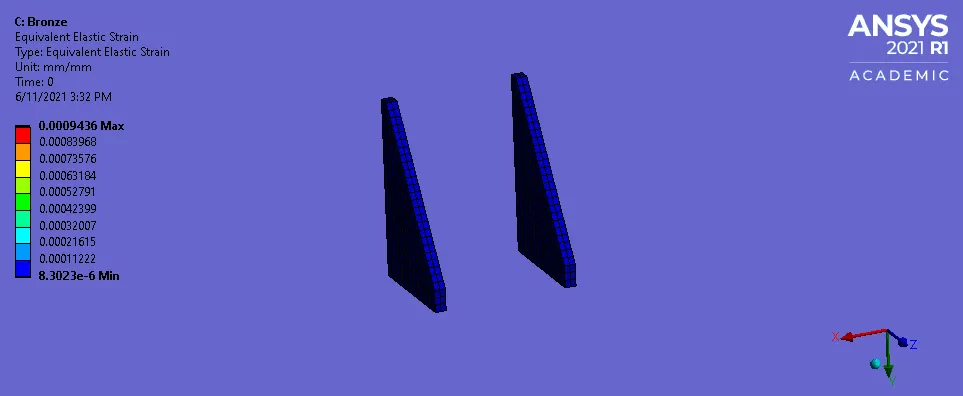
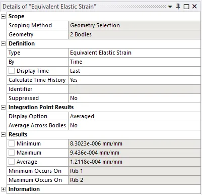
COMPARISON TABLE:
| Stress (Mpa) | Strain (mm/mm) | Deformation (mm) | Weld stress (Mpa) | |
| Case 1 | 303.31 | 7.2289E-4 | 0.31513 | 287.42 |
| Case 2 | 307.3 | 7.0661E-4 | 0.36551 | 231.7 |
| Case 3 | 311.81 | 9.436E-4 | 0.39191 | 240.9 |
- For case 1:Stainless steel, the stress in the weld is maximum.
- For case 2:Aluminium alloy, high strength, the weld stress is leeass as compared to the case 1. The material being strong, reduces the stress.
- For case 3:Bronze, the stress is slightly more than the aluminium alloy but less than the Stainless steel.
- Hence, for better strength Aluminium alloy with high tensile and yield strength provides good results.
LEARNING OUTCOMES:
- To insert material.
- To insert fixed support.
- To apply force.
- To insert face sizing in meshing.
- To request for the Safety factor.
CONCLUSION:
- Hence, by performing this project we conclude that the simulation on the weld material is performed using different materials in ANSYS.