Week 3 Verification of Weld Joints
Objective:
Simulation of three different types of welding using three different weld materials. To study effects of different types of weldments on the component and compare strengths of different types of welds.Type of weldments used determines the strength of the joint and would affect the amount of load that can be put on the component. Study of various weldments helps to determine the limit of loading that can be put on a joint and also helps to pick the load that will best satisfy the requirement of loading.
Factor of safety: While designing any Engineering product or component, safety is of utmost importance. To ensure the safety of those items, each component is designed to bear more loads than its actual operating loads. The ratio of this strength to operating laods of any material is called factor of safety of that material component.
A factor of safety of 1 represents that the stress is at the allowable limit. A factor of safety of less than 1 represents likely failure. A factor of safety of greater than 1 represents how much the stress is within the allowable limit.
Analysis of welment design
Step 1: Geometry Creation
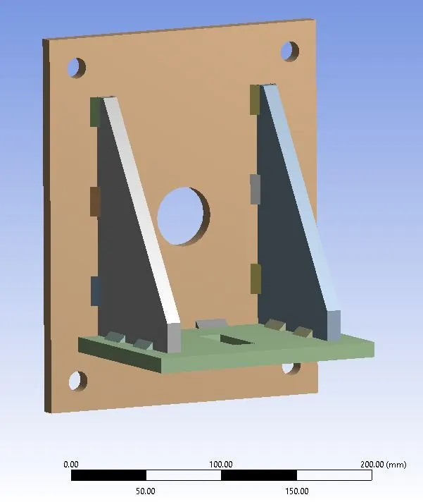
The geometry was imported from the model of bending assembly provided.
Step 2: Material Selection
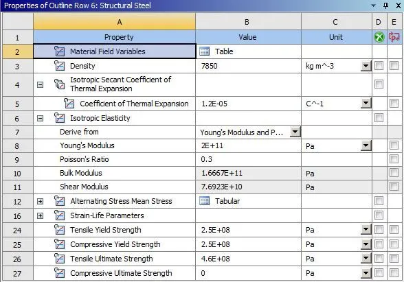
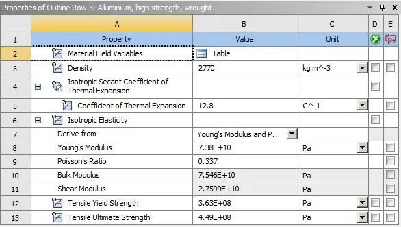
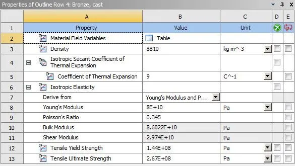
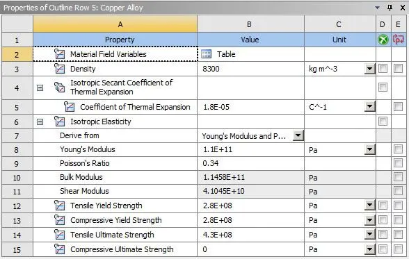
There were a total of 4 materials considered for the sheet metal in this analysis as per the problem statement. The materials used were Stainless steel, wrought aluminium, Bronze and copper. Properties for the materials are,
Step 3: Meshing
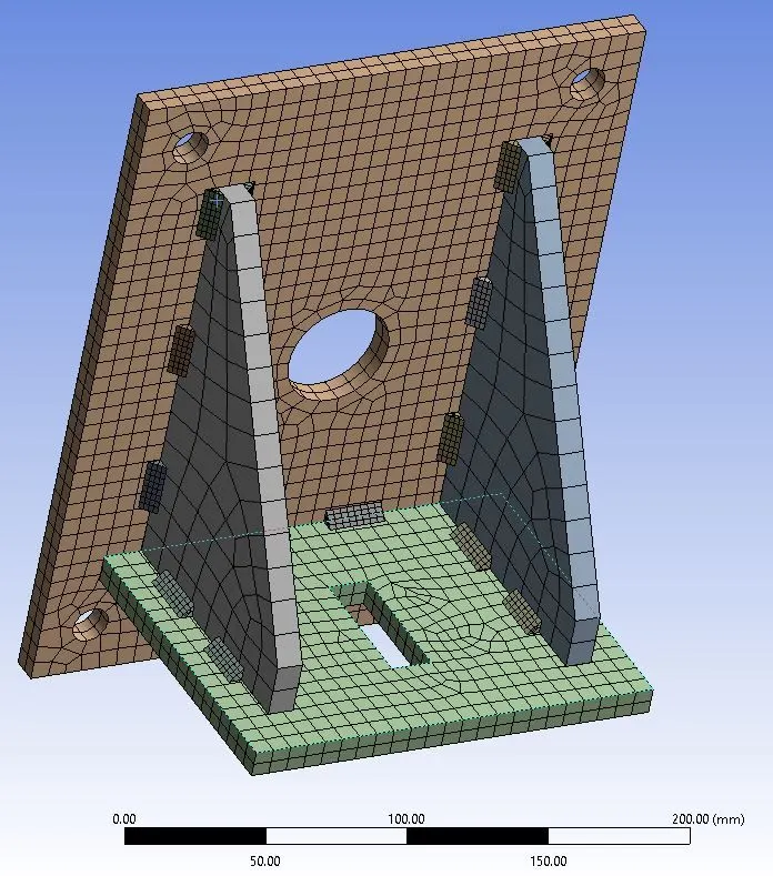
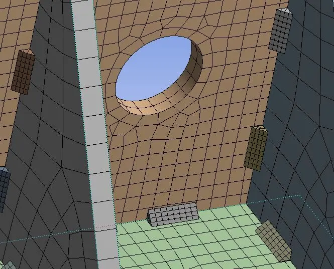
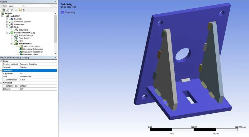
Meshing of plates attached is done considering an element size of 7 mm. Other components are meshed with an automesh since max deformation shall be observed in the plates alone and the weldments are welded with sufficiently fine mesh to calculate streeses acting on them accurately.
Step 4: Processing
Processing the model involves creation of connections, Joints, Bouindary conditions, Loads etc.
1. Creation of Connections:
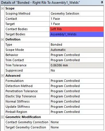
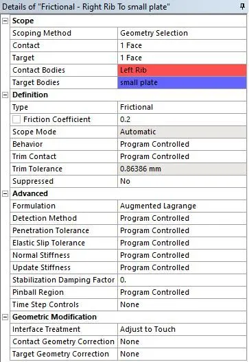
The connections already created by default are kept as is and renamed based on definition. The connections that are not connected by weldments are changed from bonded connection to friction connections with friction coefficient of 0.2. The contacts that are connected by friction connection are i) Ribs to plate connection ii) Plate to plate connection.
The properties of various contacts are,
2. Analysis settings:
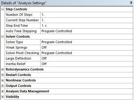
Since this analysis is a simple one, there is no need to employ multiple time steps and special solvers. The settings used in analysis setup are,
3. Application of loads:
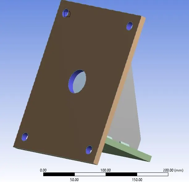
Only one load is applied on the component i.e 15000N load on the base plate of the component as shown below,
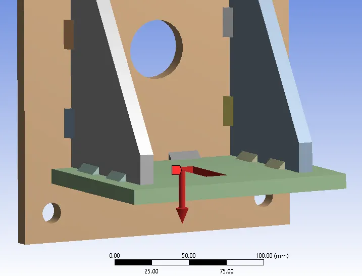
The other, vertical plate is fixed against movement in any direction at the screwhole location,
Step 5: Results and Post-Processing
The problem requires study of directional deformation of set up in Y axis as well as equivalent strain observed by the setup through the loading. We will study these parametrs on a case to case basis.
Case 1. Stainless Steel: In this case, the material of the plates must also be the same. Use Stainless steel for both weldments and plates. No need to add flux to the weldments.
Directional Deformation:
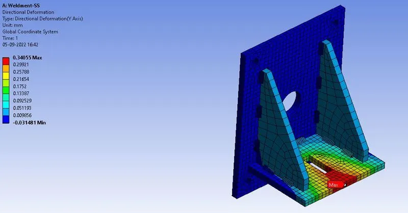
It is observed that maximum deformation occurs on the baseplate of the bracket in an area that is not resinforced with ribs. Due to this lack of strength, the baseplate will deform in that area first befor transferring the load to the ribs.
Equivalent strain:
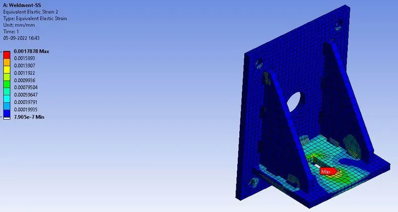
Similar to the deformation contour, the max. strain seems to be occuring in the baseplate of the bracket. The area surrounding cavity in the base plate seems to have the maximum strain since load is applied at the inner surface area of the cavity. The strain can be seen being transferred to the ribs along the weldments and the base of the ribs is seen to be strained.
Equivalent stress in weldments:
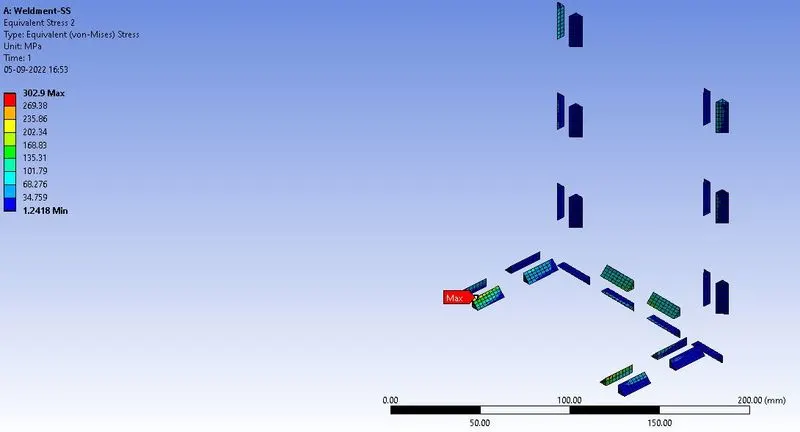
The above figure shows the distribution of stresses in the SS weldments of the bracket. In line with observations from directional deformation and strain contours, it is observed that the weldment experiencing maximum stress is the weldment at the front of the rib in tip of the baseplate. Max stress observed on the weldment is 302.9 MPa
Case 2. Aluminium Alloy:The material to be chosen for this case is Aluminium alloy(high strength, wrought). [Plate material to be used is stainless steel]
Directional deformation:
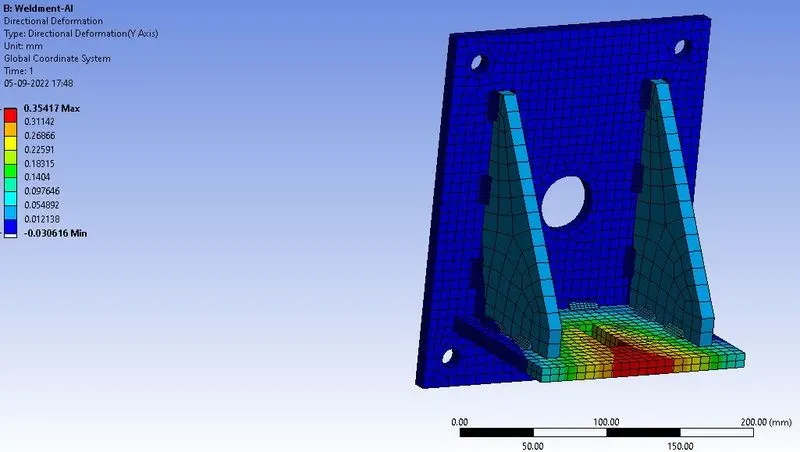
It is observed that maximum deformation occurs on the baseplate of the bracket in an area that is not resinforced with ribs. Due to this lack of strength, the baseplate will deform in that area first befor transferring the load to the ribs. Compared to SS weldments, the deformation is not significantly different as the different is of only 0.01 mm.
Equivalent strain:
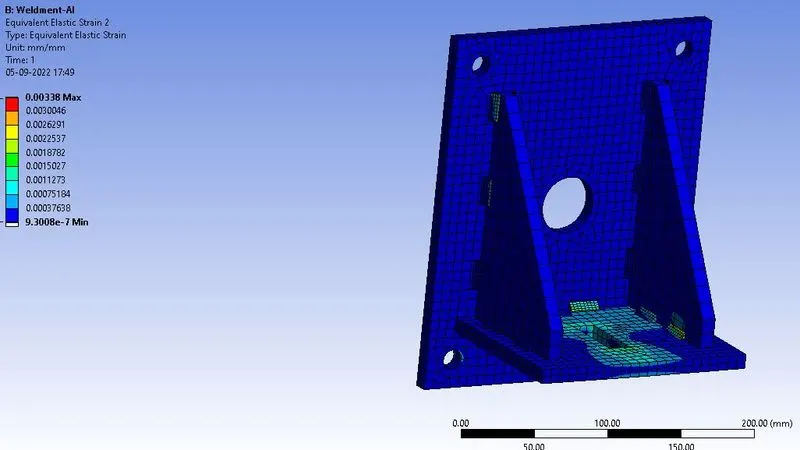
Similar to the deformation contour, the max. strain seems to be occuring in the baseplate of the bracket. The area surrounding cavity in the base plate seems to have the maximum strain since load is applied at the inner surface area of the cavity. The strain can be seen being transferred to the ribs along the weldments and the base of the ribs is seen to be strained. It was observed that max strain infact occurs in a weldment at the front of the rib in tip of the baseplate.
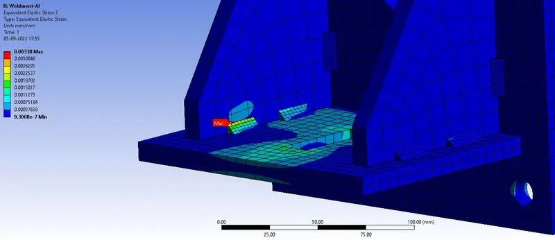
Equivalent stress in weldments:
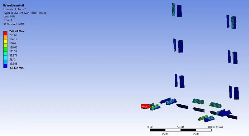
The above figure shows the distribution of stresses in the SS weldments of the bracket. In line with observations from directional deformation and strain contours, it is observed that the weldment experiencing maximum stress is the weldment at the front of the rib in tip of the baseplate. Max stress observed on the weldment is 249.24 MPa. Compared to SS weldments, this value is more than 50 MPa smaller.
Case 3. Bronze: In order to simulate "Brazing", you should be using bronze as the weld material. Assign Stainless Steel to both plates and Copper to the "Ribs".
Directional deformation:
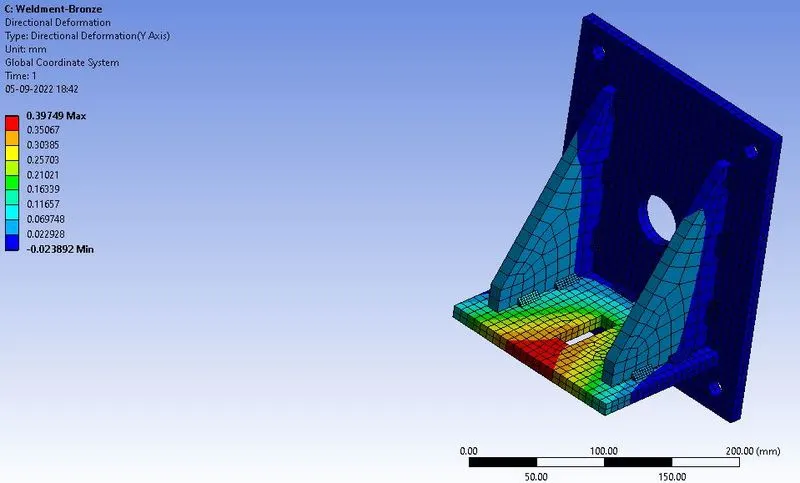
It is observed that maximum deformation occurs on the baseplate of the bracket in an area that is not resinforced with ribs. Due to this lack of strength, the baseplate will deform in that area first befor transferring the load to the ribs. Compared to SS weldments, the deformation is not significantly different as the different is of only 0.05 mm.
Equivalent strain:
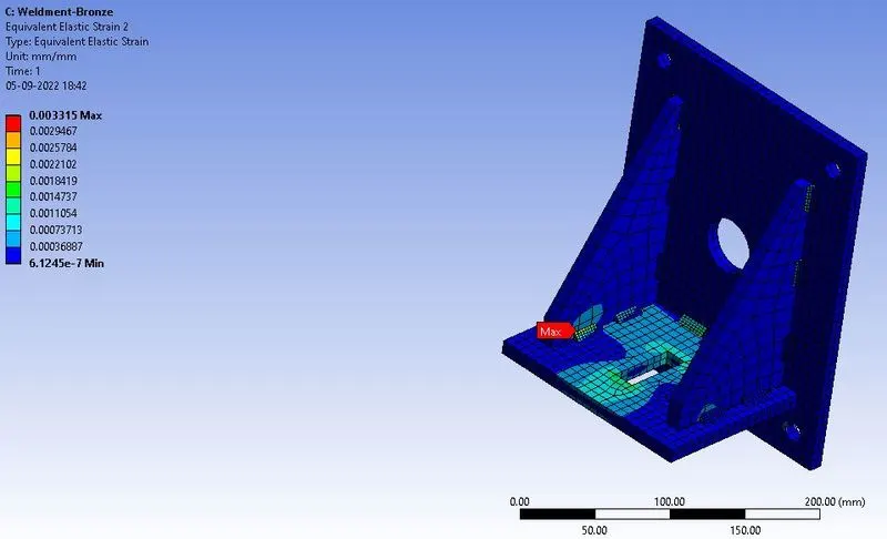
It was observed that max strain infact occurs in a weldment at the front of the rib in tip of the baseplate. This follows the same trend as of aluminium weldments and the values are remarkable similar with the values changing after 5th significant digit.
Equivalent stress in weldments:
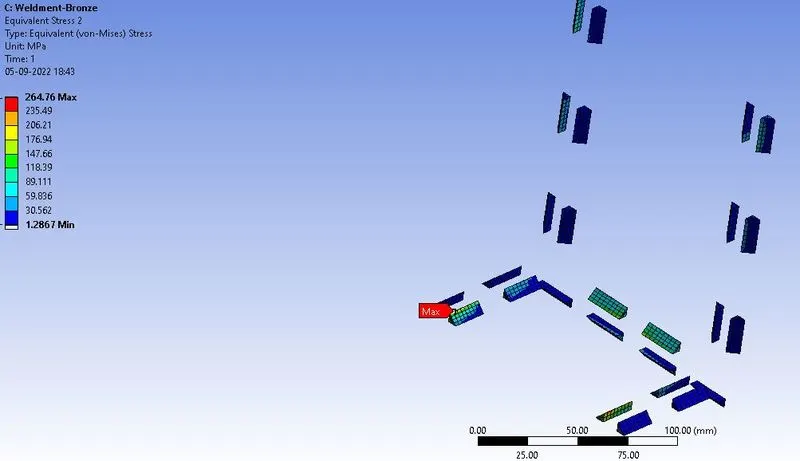
The above figure shows the distribution of stresses in the SS weldments of the bracket. In line with observations from directional deformation and strain contours, it is observed that the weldment experiencing maximum stress is the weldment at the front of the rib in tip of the baseplate. Max stress observed on the weldment is 264.76 MPa. Compared to SS weldments, this value is less by almost 40 MPa.
Conclusion:
| Results | Case-1 | Case-2 | Case-3 |
| Deformation (mm) | 0.3405 | 0.3542 | 0.3975 |
| Strain | 0.0017878 | 0.00338 | 0.003315 |
| Stress at weld joints (Mpa) | 302.9 | 249.24 | 264.76 |
Based on the results, following conclusions can be made,
- Since deformation is similar in all three cases, use of weldment does not affect deformation in plates.
- Max. strain was observed in the case of steel weldments. It should be noted that max strain in case-2 & 3 occurs in weldments whereas in steel weldments, it occurs on baseplate.
- Max strain other than weldments in case-2&3 occurs at the same place as that in case-1. The value of strain is also comparable.
- Studying stresses in weld joints, it was observed that max stress occurs in cae of aluminium weldments.