Week 3 Sheet metal Bending challenge
Case 1
AIM :
To perform sheet metal bending for 3 different materials ( Aluminium alloy 1199 , Copper alloy NL and Magnesium alloy NL ) and compare the equivalent elastic stress , elastic strain and total deformation in Y direction.
PROCEDURE :
1. Geometry :
- The model was imported on space claim .
- The individual parts of the setup were renamed accordingly.
2. Model Setup :
2.1 Material Properties :
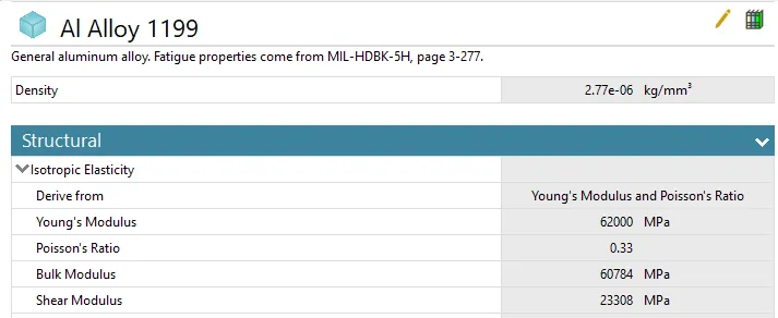
- Aluminium alloy 1199
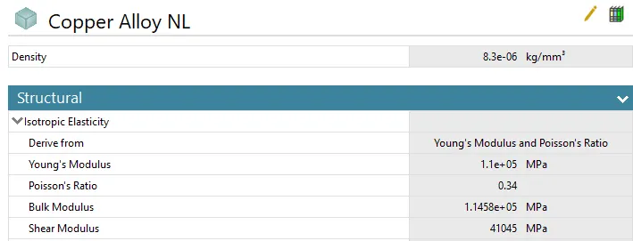
- Copper alloy NL
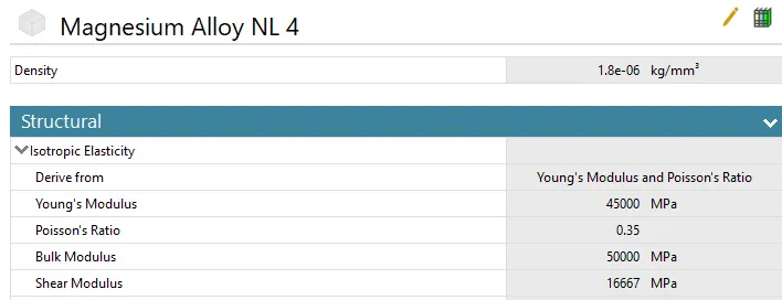
- Magnesium Alloy
2.2 Connections :
- Frictional connection of 0.1 was defined between punch to plate.
- Frictional connection of 0.1 was defined between punch to die.
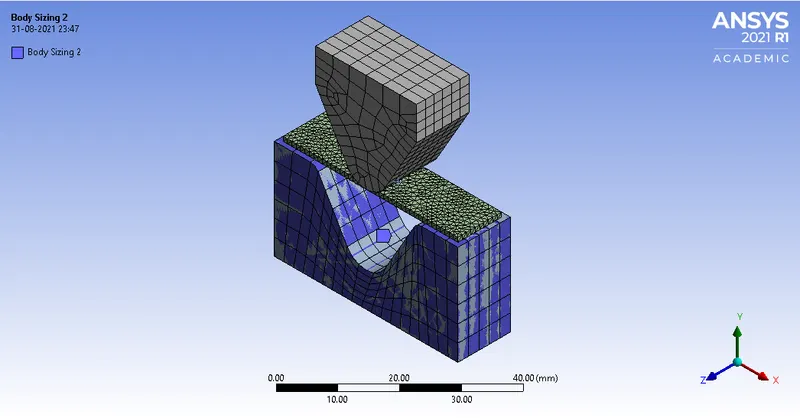
2.3 Mesh :
- Punch was defined with element size of 4 mm.
- Die was defined with element size of 4 mm.
- Plate was defined with element size of 1 mm.
- Face sizing of 1 mm was defined on faces in contact (10 faces) , tetrahedron mesh.
2.4 Analysis Settings :
- Normal Stiffness factor = 0.1
- Method is changed to Augmented Lagrange .
- Interface treatment : offset , ramped effect.
2.5 Boundary Conditions :
- Displacement of 13 mm was input on the punch in the downward direction (-Y direction ).
- 0 mm of displacement was provided on the sheet in Z direction to provide constraint to the sheet.
- Displacement of 3 mm was input on Die after the punch retracts.
RESULTS :
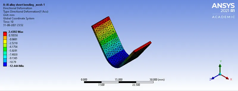
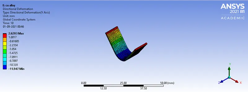
1. Total Deformation (in Y direction)
a) For Al alloy 1199
b) For Copper alloy
c) For Magnesium alloy
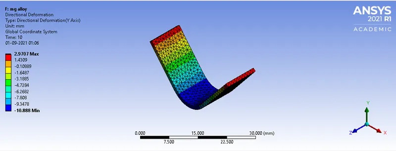
| Deformation (mm) | Al alloy 1199 | Copper alloy | Magnesium alloy |
| Maximum | 2.439 | 2.62 | 2.97 |
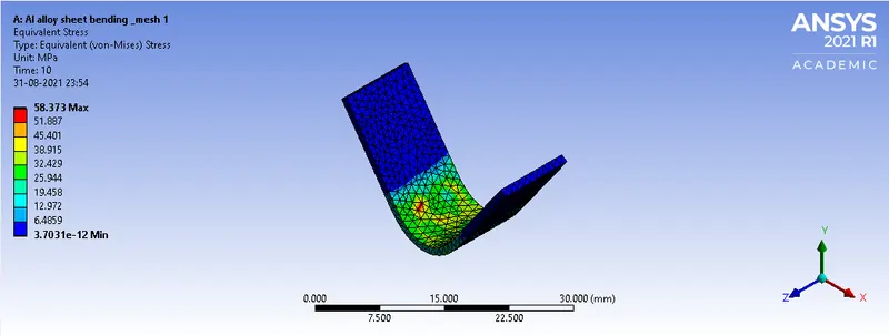
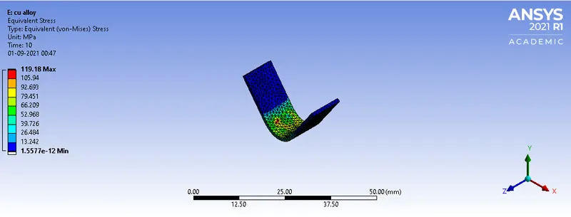
2. Equivalent Stress
a) For Al alloy 1199
b) For Copper alloy
c) For Magnesium Alloy
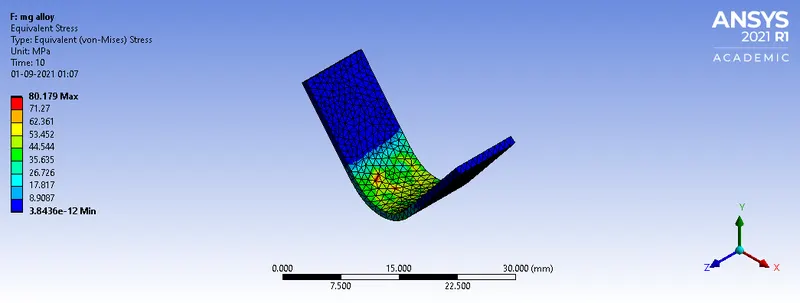
| Equivalent stress (M Pa) | Al alloy 1199 | Copper alloy | Magnesium alloy |
| Max Stress | 58.373 | 119.18 | 80.18 |
3. Equivalent strain
a) For Al alloy 1199
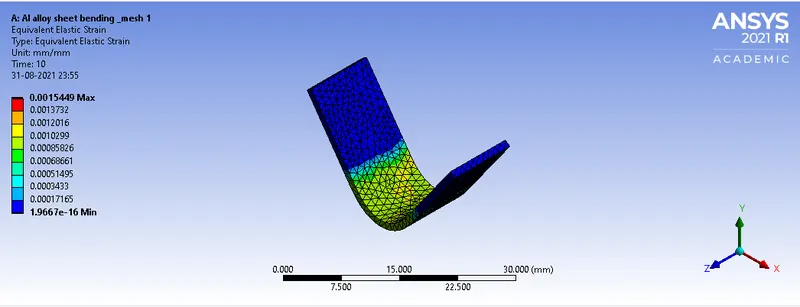
b) For Copper alloy
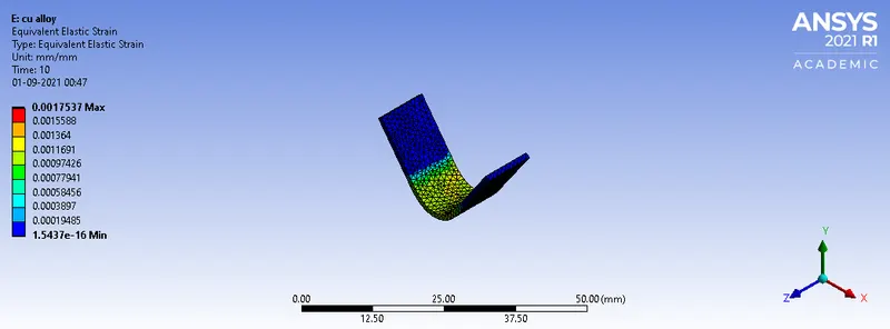
c) For Magnesium alloy
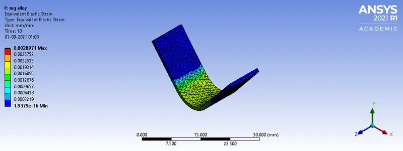
| Equivalent Strain (mm/mm)) | Al alloy 1199 | Copper alloy | Magnesium alloy |
| Max strain | 0.00155 | 0.00176 | 0.00289 |
CONCLUSION :
The max equivalent stress and the maximum equivalent strain is the lowest for Aluminium alloy case , hence this material shows better resistive property in the case of sheet metal bending , whereas Cu alloy and Mg Alloy shows the most equivalent stress and strain for the applied consitions hence it has the least resistance during the bending test.
CASE 2:
AIM :
To perform sheet metal bending for Aluminium alloy 1199 with 2 different values of coefficient of friction.
PROCEDURE :
1. Geometry :
- The model was imported on space claim .
- The individual parts of the setup were renamed accordingly.
2. Model Setup :
2.1 Material Properties :
- Aluminium alloy 1199
2.2 Connections :
- Frictional connection of 0.1 was defined for case 1 and 0.19 for case 2 between punch to plate.
- Frictional connection of 0.1 was defined for case 1 and 0.19 for case 2 between punch to die.
2.3 Mesh :
- Punch was defined with element size of 4 mm.
- Die was defined with element size of 4 mm.
- Plate was defined with element size of 1 mm.
- Face sizing of 1 mm was defined on faces in contact (10 faces) , tetrahedron mesh.
2.4 Analysis Settings :
- Normal Stiffness factor = 0.1
- Method is changed to Augmented Lagrange .
- Interface treatment : offset , ramped effect.
2.5 Boundary Conditions :
- Displacement of 13 mm was input on the punch in the downward direction (-Y direction ).
- 0 mm of displacement was provided on the sheet in Z direction to provide constraint to the sheet.
- Displacement of 3 mm was input on Die after the punch retracts.
RESULTS :
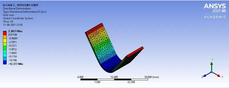
1. Total Deformation (in Y direction)
Case 1 :
Case 2:
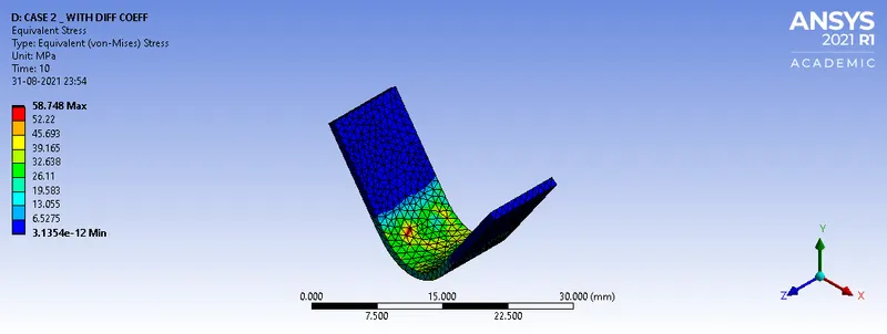
2. Equivalent stress :
Case 1 :
Case 2:
3. Equivalent Strain :
Case 1:
Case 2:
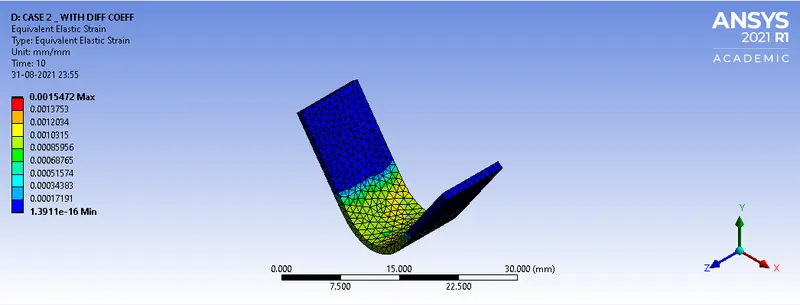
RESULT :
Results of the two comparison are tabulated below :
| Case | Directional Deformation (mm) | Equivalent Stress (MPa) | Equivalent Strain (mm/mm) |
| Case 1 | 2.439 | 58.37 | 0.00154 |
| Case 2 | 2.302 | 58.75 | 0.00155 |
CONCLUSION:
The directional deformation , equivalent stress and strain are higher in the case with greater value of friction coefficient .
CASE 3
AIM :
To perform sheet metal bending for Aluminium alloy 1199 with 2 different meshes (grid dependency test)
PROCEDURE :
1. Geometry :
- The model was imported on space claim .
- The individual parts of the setup were renamed accordingly.
2. Model Setup :
2.1 Material Properties :
- Aluminium alloy 1199
2.2 Connections :
- Frictional connection of 0.19 was defined between punch to plate.
- Frictional connection of 0.19 was defined between punch to die.
2.3 Mesh :
Case 1
- Punch was defined with element size of 4 mm.
- Die was defined with element size of 4 mm.
- Plate was defined with element size of 1 mm.
- Face sizing of 1 mm was defined on faces in contact (10 faces) , tetrahedron mesh.
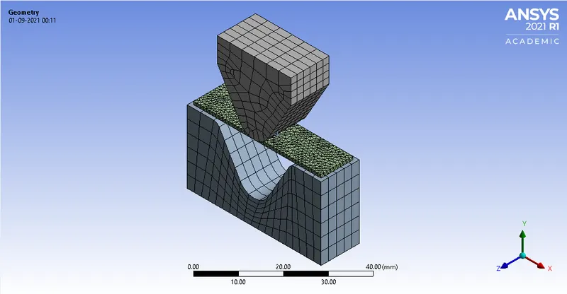
No of Nodes = 12648
No of Elements = 4943
Case 2
- Punch was defined with element size of 2 mm.
- Die was defined with element size of 2 mm.
- Plate was defined with element size of 1 mm.
- Face sizing of 1 mm was defined on faces in contact (10 faces) , tetrahedron mesh.
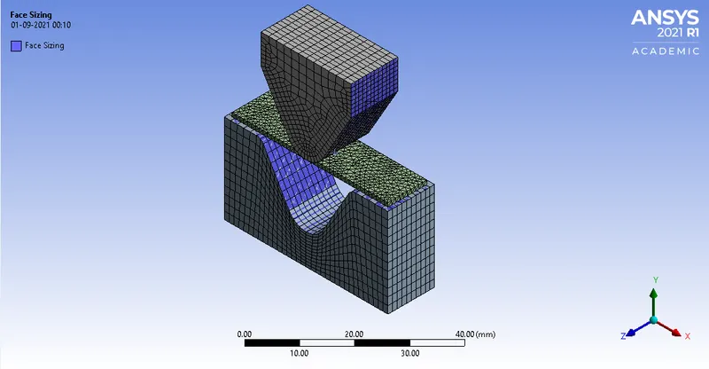
No of Nodes = 40994
No of elements = 11165
2.4 Analysis Settings :
- Normal Stiffness factor = 0.1
- Method is changed to Augmented Lagrange .
- Interface treatment : offset , ramped effect.
2.5 Boundary Conditions :
- Displacement of 13 mm was input on the punch in the downward direction (-Y direction ).
- 0 mm of displacement was provided on the sheet in Z direction to provide constraint to the sheet.
- Displacement of 3 mm was input on Die after the punch retracts.
RESULTS :
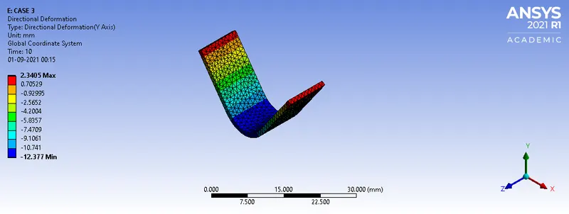
1. Total Deformation (in Y direction)
Case 1 :
Case 2 :
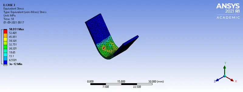
2. Equivalent Stress :
Case 1 :
Case 2 :
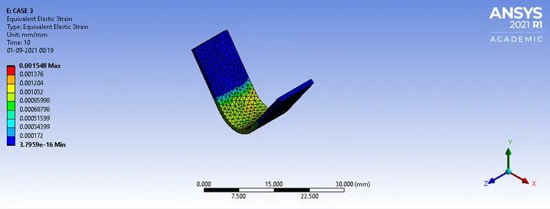
3. Equivalent Strain :
Case 1 :
Case 2 :
RESULT
Results of the two comparisions are tabulated below :
| Case | Directional deformation (mm) | Equivalent Stress (MPa) | Equivalent Strain (mm/mm) |
| Case 1 | 2.3021 | 58.748 | 0.00155 |
| Case 2 | 2.3405 | 58.951 | 0.00155 |
CONCLUSION :
The results of Case 2 are comparetively greater than that of Case 1 due to finer meshing of Case 2 , the results are relatively sharper . Increasing the mesh size furthur more will not lead to a change in the results obtained .