Week 2 Railwheel and Track
REPORT :
AIM:
To perform static structural simulation on rail-wheel and steel track model with diffrent bearing loads, and compare Total deformation,Equivalent stress and life under the diffrent loads.
PROCEDURE :
1.Geometry :
- The model was loaded on space claim and material was selected as structural steel.
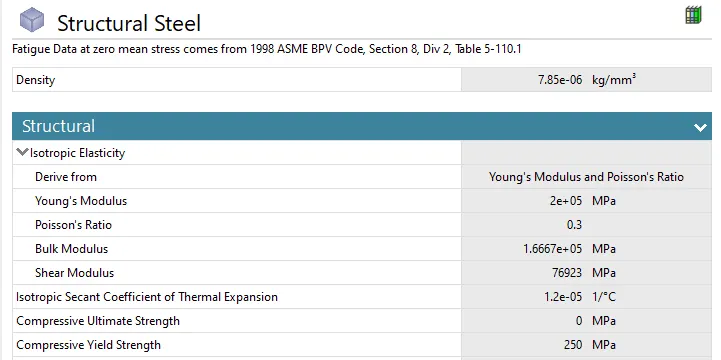
- Material properties:
2.Model Setup :
Connections & Joints:
- Frictional contact with coefficient of 0.3 was defined bewteen wheel and Rail track.
- Frictionless contact was defined between axle shaft and wheel.
- 'Translational' joint was deinfed for axle shaft.
- 'Fixed' joint was defined for rail track .
- 'Planar' joint was defined for rail wheel (so as the wheel stays on the same plane during motion)
Meshing :
- The default sizing was set as 50 mm .
- Face sizing of 35mm was defined between wheel rim and track ( as these part are in CONSTANT contact with each other).
- Mesh:
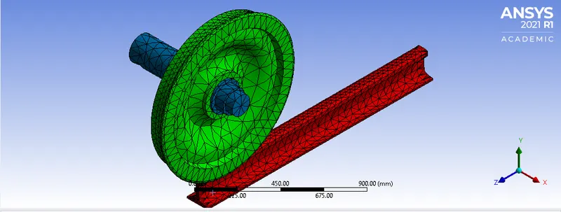
- No of elements : 6726
No of Nodes : 13304
Boundary Conditions :
- Bearing load of 100000 and 500000 N were applied saperately on rail wheel bearing in two diffrent models.
- Displacement of 500 mm was defined for axle shaft (in translational motion).
RESULT :
Note:
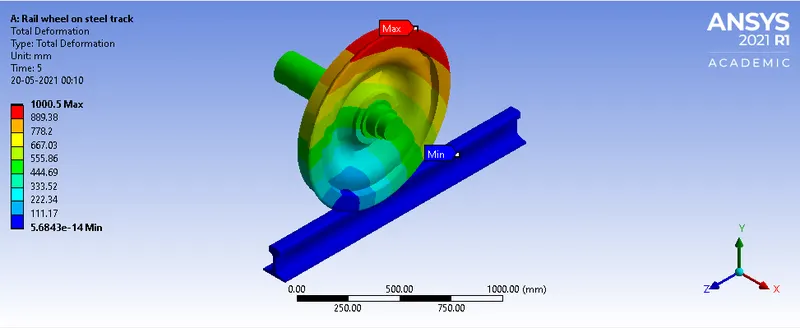
Case 1 : model with bearing load 100000 N
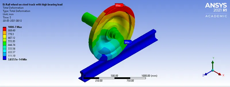
Case 2 : model with bearing load 500000 N
1.Total deformation:
| Deformation (mm) | |
| Case 1 | 1000.5 |
| Case 2 | 1000.7 |
case 1:
case 2:
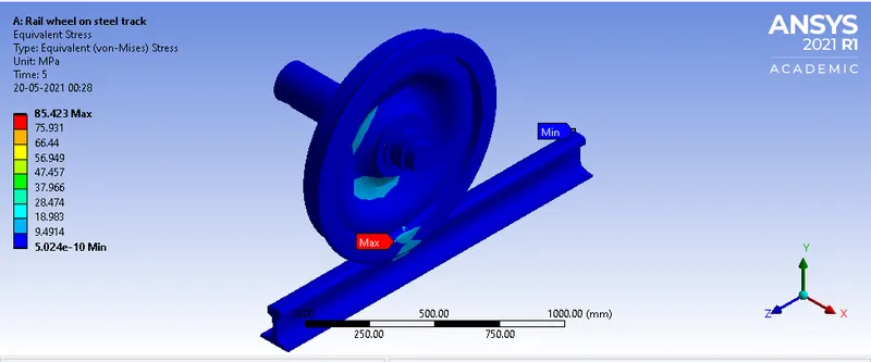
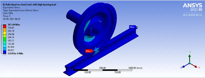
2.Equivalent stress :
| Maximum stress (MPa) | whole setup | rail wheel | steel track |
| Case 1 | 85.42 | 85.42 | 72.148 |
| Case 2 | 367.44 | 367.44 | 298.76 |
Case 1:
Case 2:
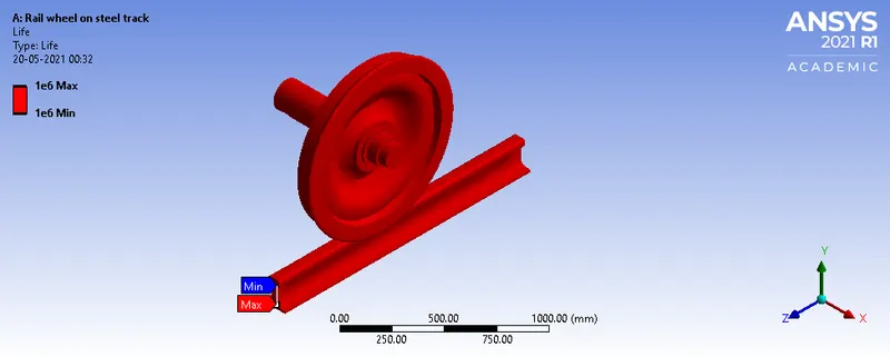
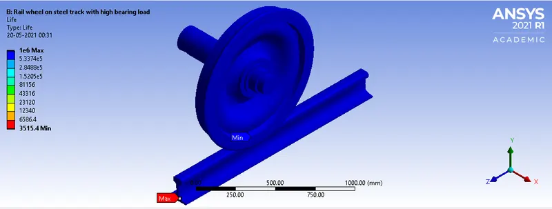
3.Fatigue Life:
| Fatigue life (no of cycles) | Maximum | Minimum |
| Case 1 | 1000000 | 1000000 |
| Case 2 | 1000000 | 3515.4 |
Case 1:
Case 2:
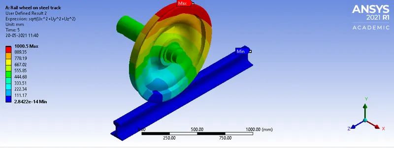
4.User defined result :
The maximum deformation in user defined result generated in the case 1 is same as the solution generated by the ANSYS workbench, however the minimum deformation differs.
Expression used : sqrt(Ux^2 + Uy^2 + Uz^2)
ANYSYS generated total deformation:
User generated result:
5. Fcator of Safety :
- Case 1: 2.92
Case 2: 0.68 - FOS for Case 2 is less than 1 , which exceeds the design parametre.
- Maximum stress permissible for this setup is <125 MPa.
- Bearing Load should not excede 100000 N so as for the longer life of the rail wheel and steel track.
CONCLUSION :
Since the applied bearing load in Case 2 is greater than Case 1, Case 2 depicts more amount of equivalent stress , strain and a shorter fatigue life, total deformation is same for both the cases. The bearing load on the Rail wheel should not excede 100000 N for better fatigue life of the Rail wheel and less wearing of steel track.