Week 1 Spur Gear Challenge
1. Equivalent stress, Deformation & Stress intensity For the 3 cases are tabulated in the table below:
| Cases |
Equivalent Stress (MPa) |
Total Deformation (mm) | Stress Intensity (MPa) |
| Case 1(Ductile Cast Iron) | 342.55 | 30 | 355.8 |
| Case 2(Cast Steel) | 335.58 | 30 | 351.93 |
| Case 3(Cast Bronze) | 342.12 | 30 | 363.82 |
______________________________________________________________________________
2.Report Generation:
Aim:
To simulate and compare the deformation, maximum stress and stress intensity on Bevel gear with the following 3 diffrent materials.
- Cast iron (ductile)
- Cast steel
- Cast Bronze
Setup & Procedure :
1.Engineering Data & Geometry setup:
- Three diffrent models were setup on Ansys workbench using the given geometry of Bevel Gear.
- Following are the 3 diffrent cases generated:
Case 1: Spur gear with Cast Iron as material
Case 2: Spur gear with Cast Steel as material
Case 3: Spur gear with Cast Bronze as material.
2. Model setup:
Defining Contacts & Joints :
- The contacts & joints between the body were defined as per the figure below :
Contact type - Frictionless
Formulation - Augmented Lagrang
Joint - 'Revolute' Joint on Both the gears , connection type was defined as "body to ground".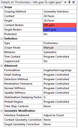
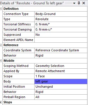
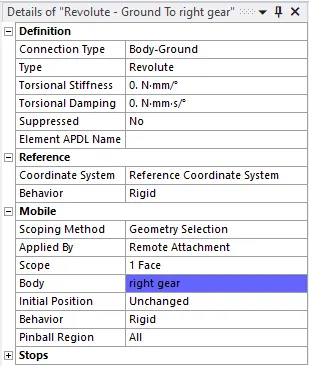
Fig 1 : Contacts Fig 2 : Joint on left gear Fig 3 : Joint on right gear
Mesh
- Element size was defined as "1 mm"
- Smoothing was set to low .
- Number of Elements : 3760
- Number of Nodes : 21206
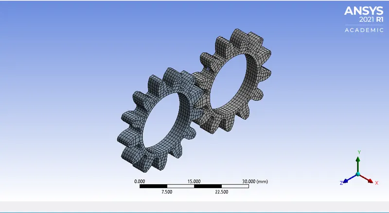
Fig 4 : Meshing on the gears
Boundary Conditions:
- The right gear was provided with a moment of 10 Nm acting on centre in Anti clockwise direction.
- The left gear was defined by rotation of 180 Degrees.
Result:
1. Deformation comparison :
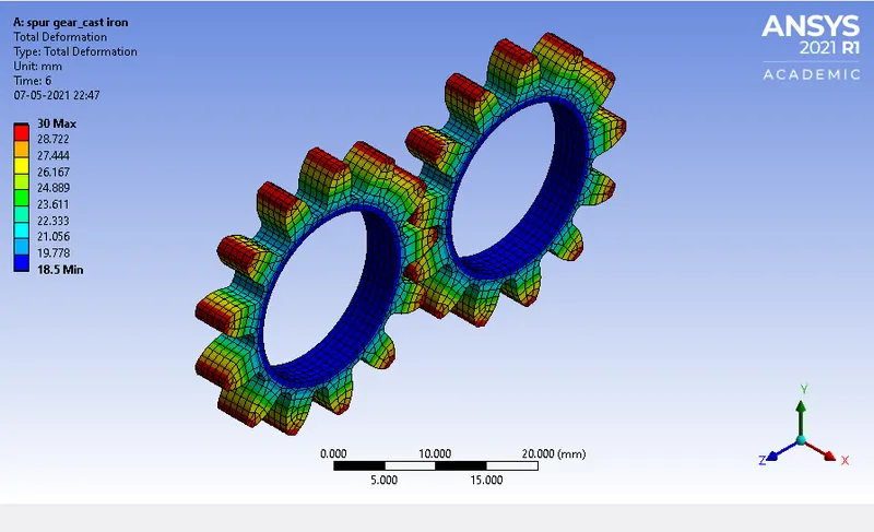
Fig : Spur gear with cast iron (Case 1)
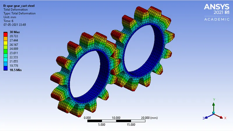
Fig : Spur gear with cast steel (Case 2)
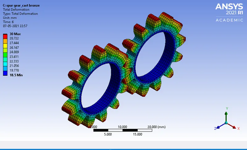
Fig : Spur gear with cast bronze (Case 3)
- Deformation in all the three cases are same.
2. Equivalent Stress Comparison :
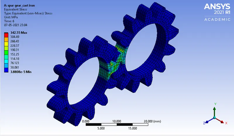
Fig : Spur gear with cast iron (Case 1)
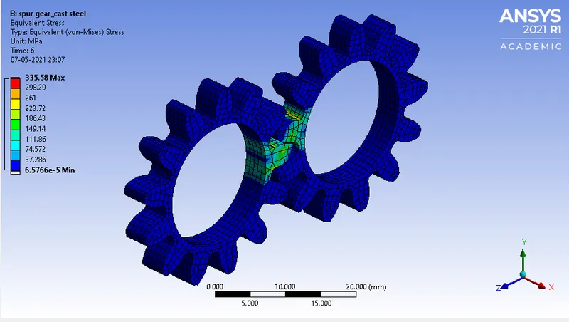
Fig : Spur gear with cast steel (Case 2)
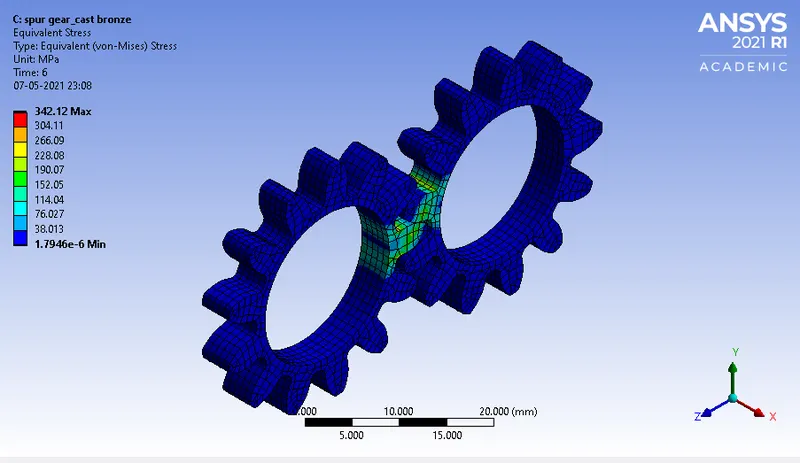
Fig : Spur gear with cast bronze (Case 3)
Factor of safety For each cases
| Maximum Equivalent Stress (MPa) | Maximum Yield Stress (MPa) | Factor of Safety | Stress Intensity (MPa) | |
| Case 1 | 342.55 | 79.8 | 0.233 | 355.8 |
| Case 2 | 335.58 | 349 | 1.04 | 351.93 |
| Case 3 | 342.12 | 144 | 0.42 | 363.82 |
3. Stress Intensity Comparison:
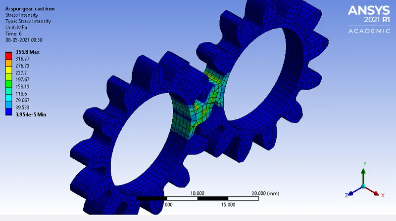
Fig : Spur gear with cast iron (Case 1)
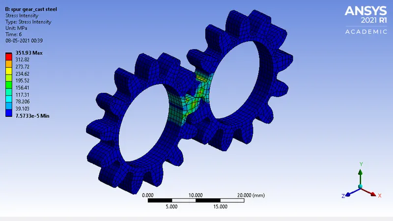
Spur gear with cast steel (Case 2)
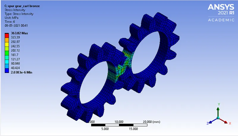
Spur gear with cast bronze (Case 3)
Key Points:
- For any body in motion and in contact with another body , the comparison of the cases for selection of the material for gear is done using Fatigue life cycle calculation or Damage analysis.In the present cases, life cycle table is not available for the given material.
- Hence the selection or preferences of the material is done using FOS calculation and stress intensity.
- For the given Three Cases, FOS is highest for Case 2, and stress intensity is lower for this case as compared to others.
- Hence Cast steel should be selected for designing Spur gear in the given problem statement.
Conclusion :
For the given problem statement , Cast steel was found to be a better material for manufacturing of spur gear.
______________________________________________________________________________
Note: The animations of Equivalent stress generation for all the three cases have been attached below .