Week 2 Bevel Gear Challenge
1. Grid Dependency test :
The material is divided into smaller number of elements and nodes , this structure is called mesh.The sizing of mesh defines how small or big the elements is going to be. More finer the mesh size, more accurate the results we get, but there is a limitation. The more finer we do the meshing , it takes more time for the processor to solve the simulation. After some interations on mesh size , the percentage of variation in results tends to zero.Hence we need to find an optimum size of mesh for each problem statement ,after which when we make the mesh more finer, it does not affects the result.This is called grid dependency test.
Report:
AIM :
To perform a grid dependency test on Bevel gear and fine the equivalent stress, equivalent strain and total displacement for 4,5 and 6 mm mesh size.
PROCEDURE :
1.Geometry :
- The geometry was exported on space claim as per the diagram given in the problem statement.
- The unwanted parts of the gear were removed on the same.
2.Model Setup :
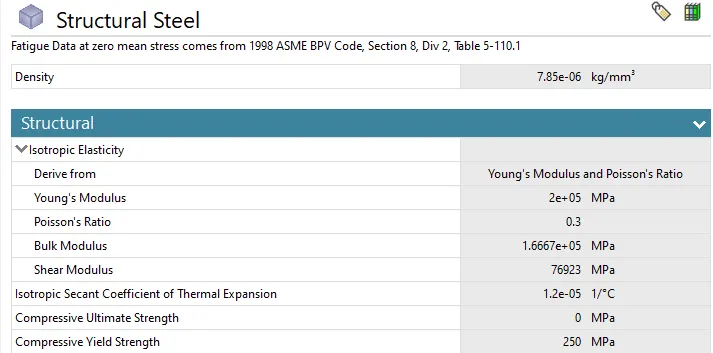
2.1 Material & Properties :
2.2 Connections :
- Frictional contact of coefficient : 0.2 was defined between the faces of the gears , behaviour was set to symmetric and formulation to Augemented Lagrange.
- Revolute Joint was defined for the both the gears
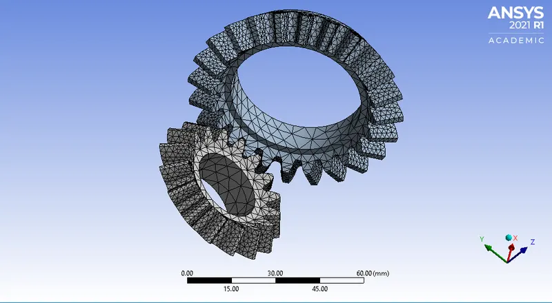
2.3 Mesh :
- Face sizing was introduced to all the faces of the gear in contact and was set to 1.75 mm, Behaviour was set to 'soft'.
- The element size was termed as 'parametric' , and was set to 4,5 and 6 mm values.
- No of Nodes: 24506
- No of elements : 13127
2.4 Analysis settings :
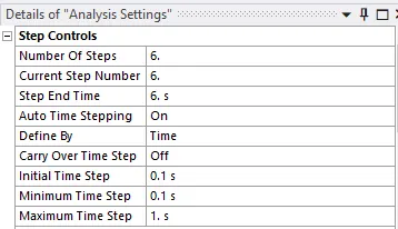
- Rotation of 20 degree was defined at each step for smaller gear (total revolution of 120 degree )
- Moment of 100 Nm was defined for the bigger gear .
2.5 Parametric setting :
- Input parametre was set as mesh sizing for 4,5 and 6 mm .
- Output parametre was set as Equivalent stress, equivalent strain, total displacement and fatigue life.
Results :
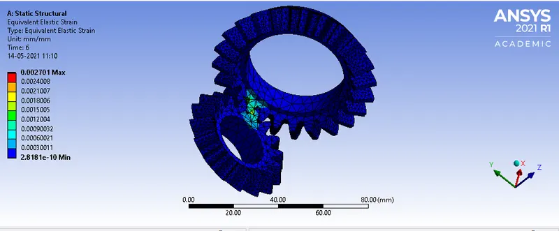
Equivalent elastic strain:
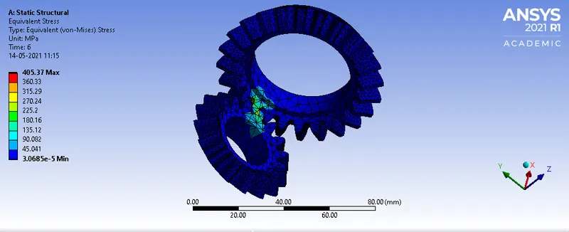
Equivalent stress:
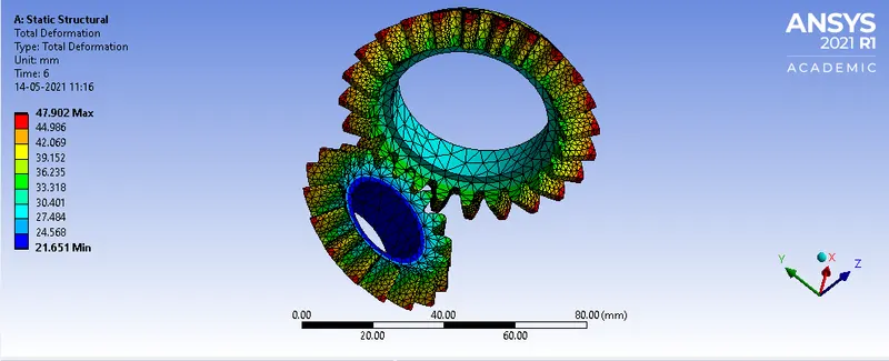
Total displacement :
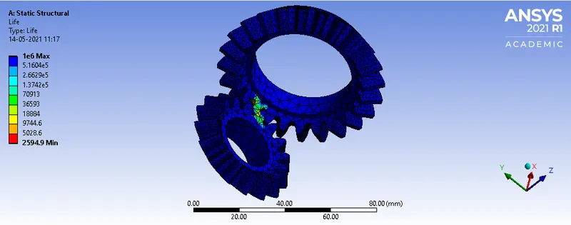
Fatigue Life :
Parametric comparison between 3 diffrent mesh sizes:
| Mesh Element Size [mm] | Equivalent Elastic Strain Maximum [mm mm^-1] | Equivalent Elastic Strain Average [mm mm^-1] | Equivalent Stress Maximum [MPa] | Equivalent Stress Average [MPa] | Total Deformation Maximum [mm] | Stress Intensity Maximum [MPa] | Life Minimum |
| 4 | 0.002700952 | 3.75E-05 | 405.3672061 | 6.304084448 | 47.90243455 | 445.4292598 | 2594.934014 |
| 5 | 0.002600543 | 3.83E-05 | 382.5376735 | 6.407700994 | 47.90249437 | 420.0580563 | 3104.117257 |
| 6 | 0.002560887 | 3.75E-05 | 379.2293929 | 6.278154766 | 47.9024349 | 411.7666112 | 3188.582913 |
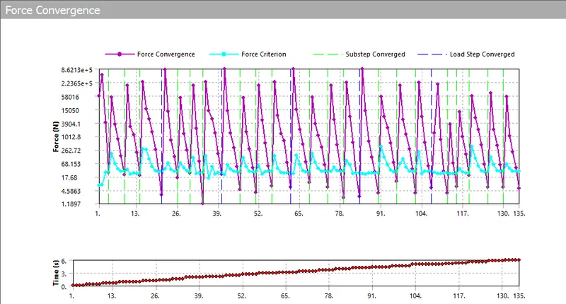
Force conversion chart for mesh size 4 mm:
Factor of safety :
- Factor of safety for the given model = yield stress/workign stress
= 250/405.37 = 0.617
- The value of factor of safety should be always greater than 1 and depending upon design parametres **
Conclusion :
Grid dependency was performed on the gear pair , and it is concluded that finer the mesh size, more accurate are the results upto a certain value of the mesh size , and percentage deviation between the results are less.