Week 3 Sheet metal Bending challenge
PROCEDURE:
- Drop Static Structural
- Rename it as per the material
- Right click on Geometry and click on import
- Import the Geometry
- Right click on Geometry and click on Update
- Right click on Model and select Edit
- Rename the Geometry name in Mechanical module
- Rename as Punch, Sheet and Die
- Select the sheet and assign the material as per the case
- Delete all the default contacts
- Right click and select Manaual contact region
- Select the faces of Punch and sheet that will be in contact and target and apply
- Again select Manual Contact region, this time select the faces of Sheet and die that will be in contact and target and apply
- Select both the contacts and Change type to frictional
- Change the Formulation to Augmented Lagrange and add Frictional Coeefficient as 0.1
- Select Normal Stiffness as Factor
- Give value of 0.1 to Normal Stiffness Factor
- Change Interface treatments to Add offset, Ramped effects
- After Meshing Click on Analysis settings
- Let steps be 10 steps
- Select the 10 steps using shift key, switch on the Large deflection
- Let solver type be direct
- In non linear section select the stablization as constant
- Change energy Dissipation Ratio to 0.1
- We may select the output Parameters after Applying Load.
Applying Load:
- For Punch - Select the top 3 faces of Punch, click on Static structural and apply Displacement
- Select Tabular for X.Y and Z axis.
- Give input for negative Y direction.
- For Sheet - Select the faces in Z direction and fix them. Right click on Static structural and apply Displacement and select tabular for Z direction
- For Die - Give input for last two steps in Y direction so that Die withdraws after punching.
Meshing:
- Right click and select sizing, select the solid filter and select Punch and Die and give 4mm value as size
- Similarly, insert sizing and select sheet. apply 1mm mesh
- Right click select the faces in contact and apply 1mm mesh
- Right click, select the Method as tetrahedron and select the sheet, then click apply
- Right click on mesh and click generate Mesh
Case 1:
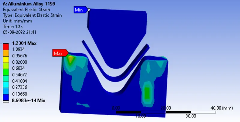
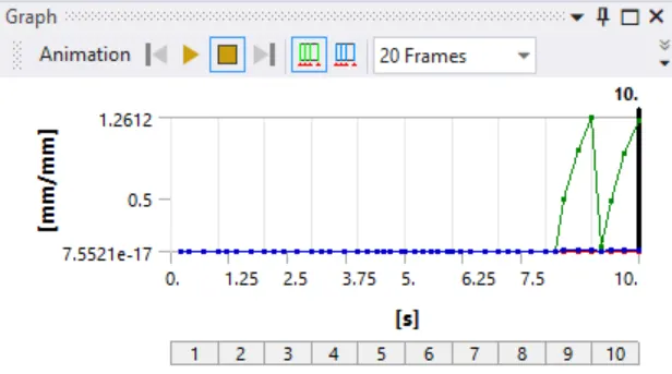
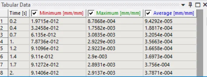
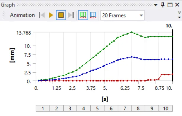
Objective - To Find out the Equivalent stress, Equivalent elastic strain, and Total Deformation in the Y direction and compare the results for the three materials. Aluminium Alloy 1199( mentioned in the course video), Copper Alloy NL, and Magnesium Alloy NL
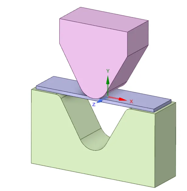
Material:
1. Alluminium Alloy 1199
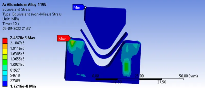
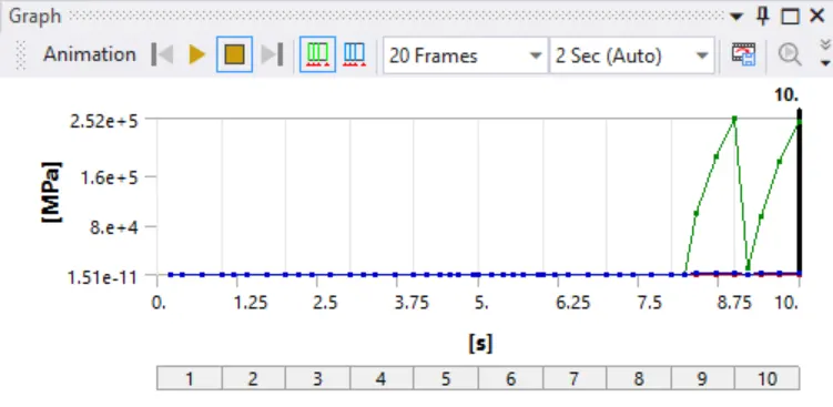
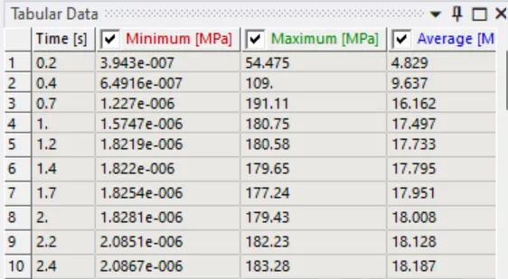
Equivalent Stress -
Equivalent Strain:
Total Deformation:

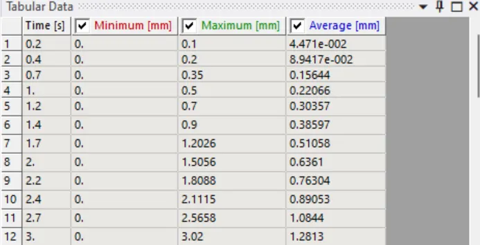
2. Copper Alloy NL
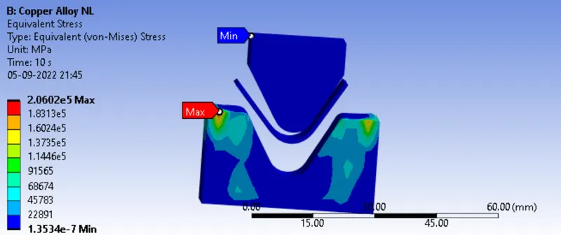
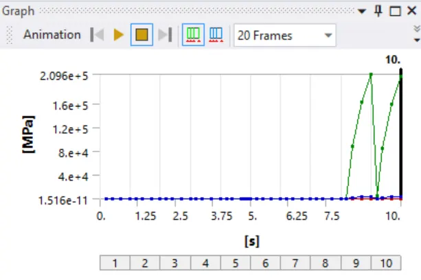
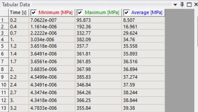
Equivalent Stress:
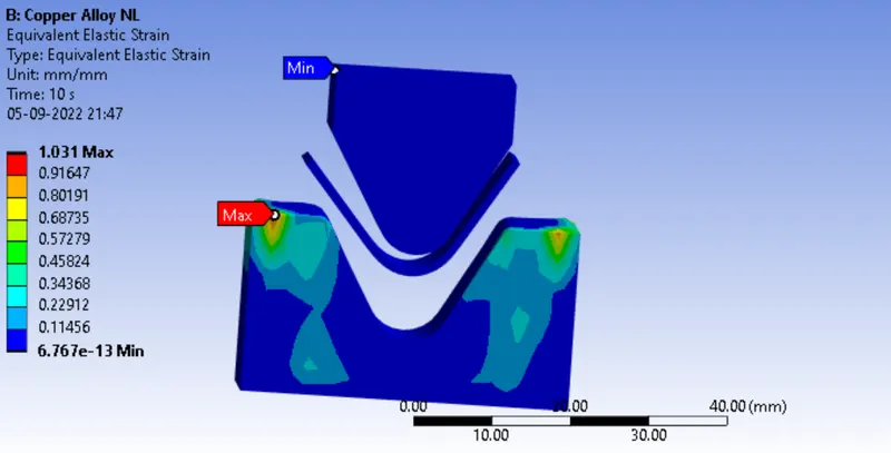
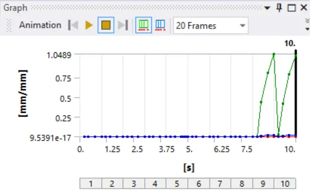
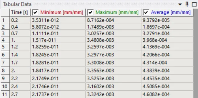
Equivalent Strain:
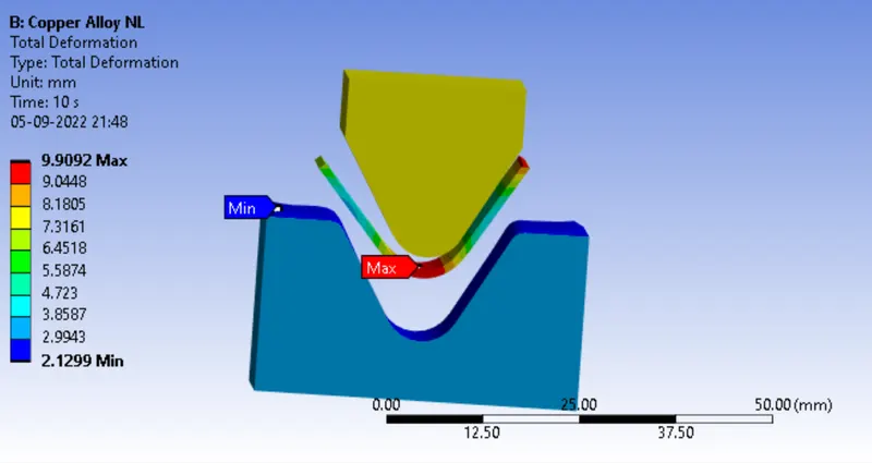
Total Deformation:
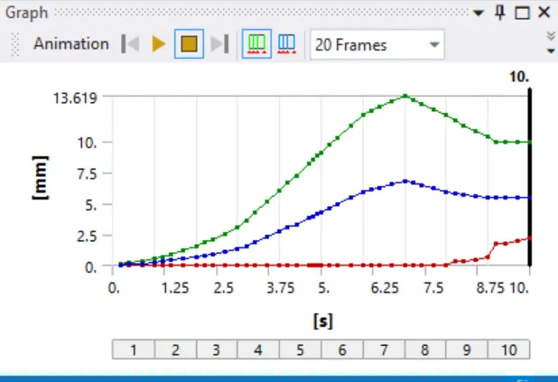
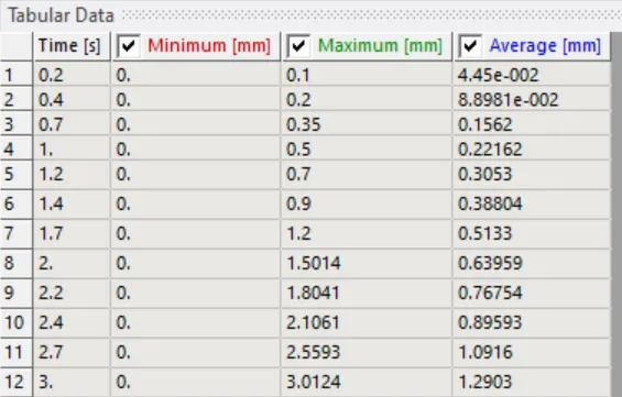
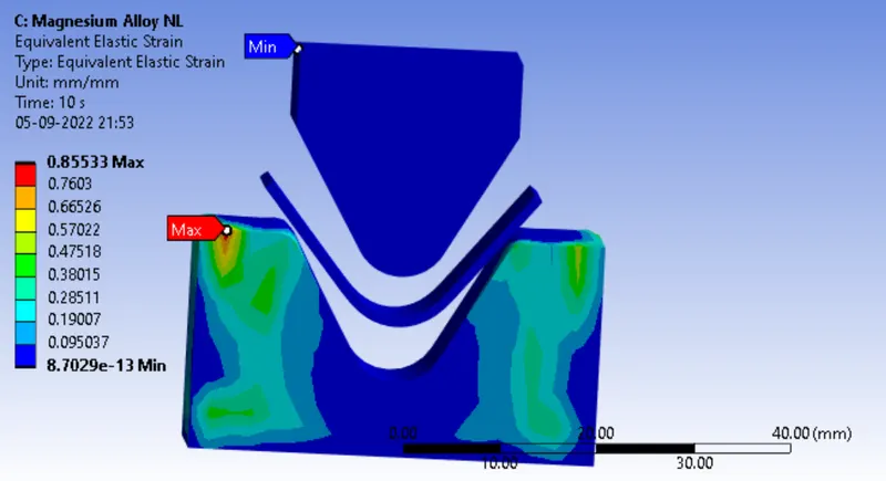
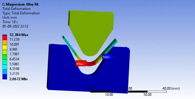
3. Magnesium Alloy NL:
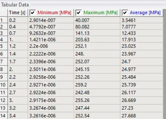
Equivalent Stress:
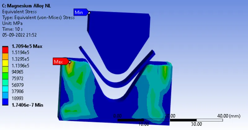
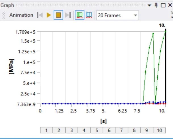
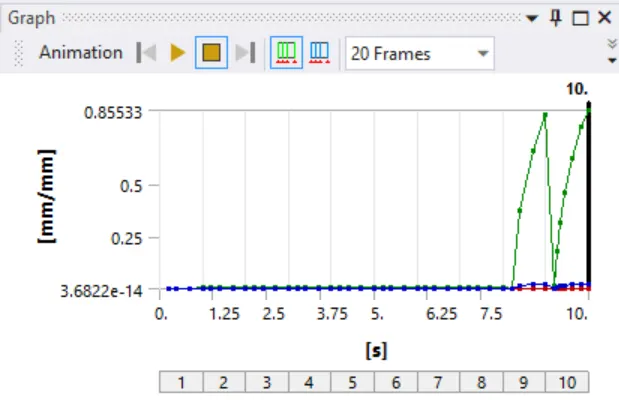
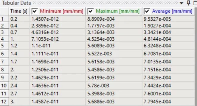
Equivalent Strain:
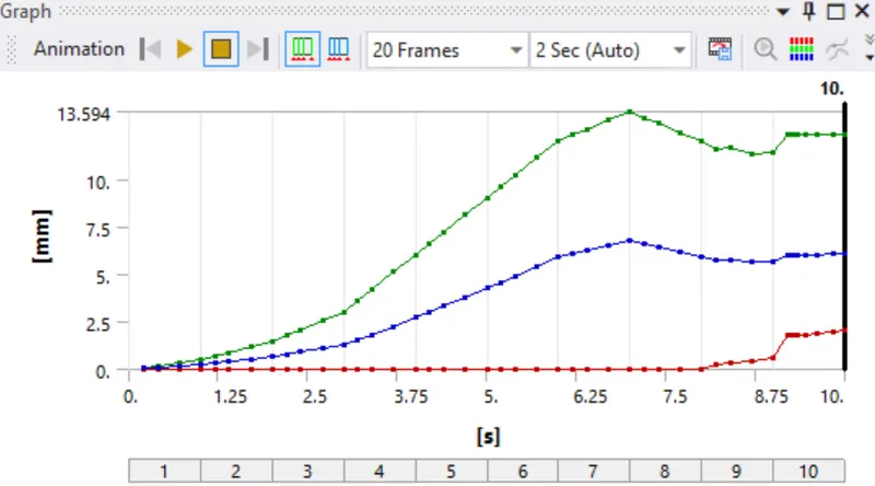
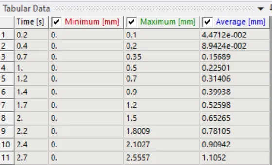
Total Deformation:
RESULT:
| S. No | Material | Euivalent Stress (MPa) | Equivalent Strain | Total Deformation (mm) |
| 1 | Alluminium Alloy 1199 | 2.4578e5 | 1.2301 | 12.492 |
| 2 | Copper Alloy | 2.0602e5 | 1.031 | 9.9092 |
| 3 | Magnesium Alloy | 1.7094e5 | 0.85533 | 12.384 |
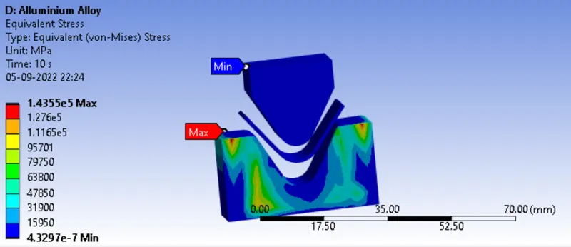
| 4 | Alluminium Alloy | 1.4355e5 | 0.71793 | 11.898 |
Conclusion:
- Alluminium Alloy 1199 has the highest stress, Strain and Total Deformation.
- Alluminium Alloy with Frictional coefficient 0.19 has lesser Stress, Strain and Total Defromation as compared to Alluminium Alloy 1199.
CASE 2:
Objective: With the material as Aluminium Alloy, change the friction coefficient to 0.19 and run the analysis as mentioned in Case 1. Compare the results with that in case 1.
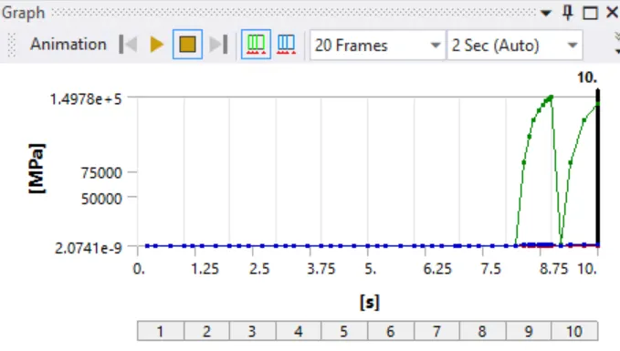
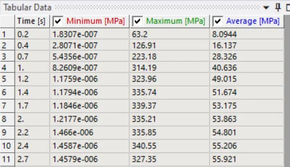
Equivalent Stress:
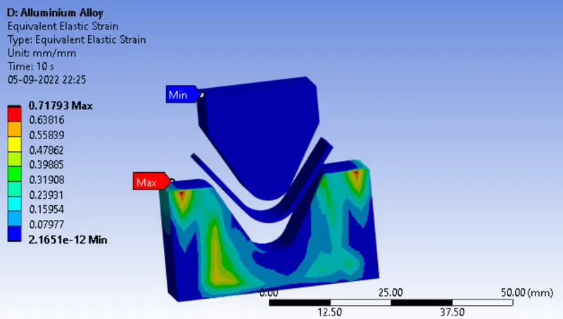
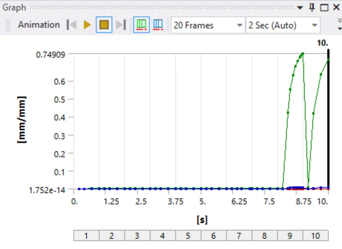
Equivalent Strain:
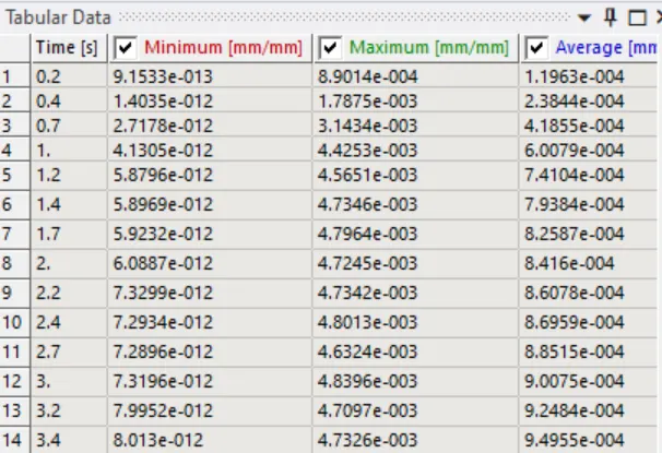
Total Deformation:
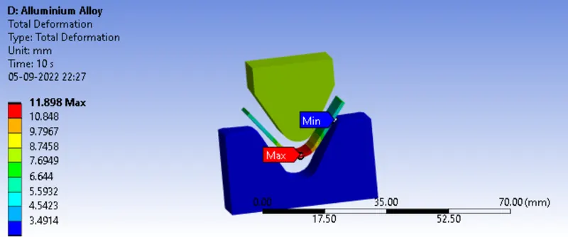
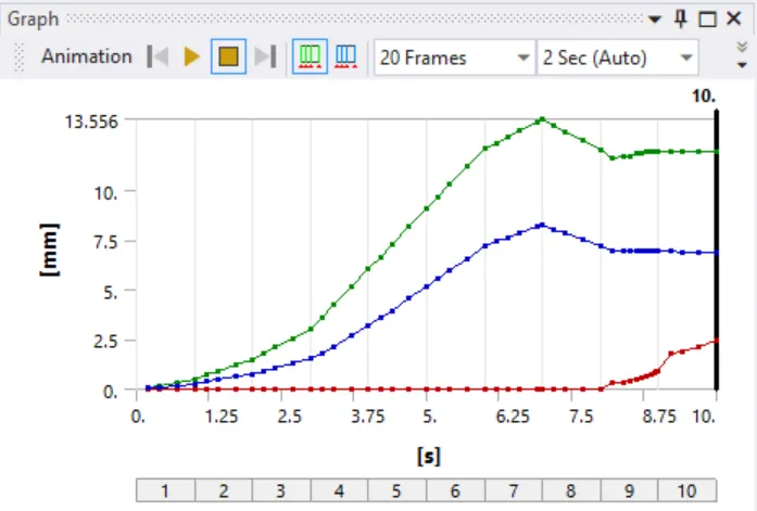
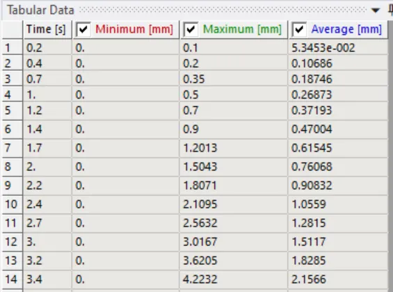
Conclusion: Alluminium Alloy with Frictional coefficient 0.19 has lesser Stress, Strain and Total Defromation as compared to Alluminium Alloy 1199.
CASE 3:
Objective: Refine the mesh on the plate such that it doesn't cross the academic limit. With Aluminium alloy as material, run the analysis as in Case 1 and compare the results.
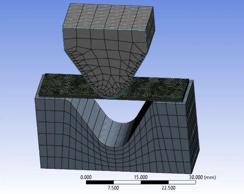
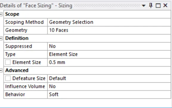
Procedure: Right click on Mesh and select sizing, select the solid filter and select Sheet. Now apply 0.5 mm sizing for finer mesh. Right click on mesh and select generate Mesh.
Conclusion : With mesh size of 0.5 Alluminium alloy has lesser stress as Compared to material Alluminium Alloy 1199.