Week 2 Railwheel and Track
Objective:
Case 1: Multiply the bearing load by 5 times and compare the results with the load of 100000 N (As done in week 2 video). Compare the Total Deformation, Equivalent stress, and the life under both the loads.
PROCEDURE:
- Open the static structural
- Import the geometry by right clicking on it
- Right click on model and edit it
- Select the default contacts and right click on it, select rename based on definition
- Flip the contacts
- Define the contacts between wheel and track and assign frictional coefficient of 0.3
- Define shaft and wheel to be frictional
- Click on connections and assign 3 Joints- Planar, Translational and Fixed
- Fixed Joint - For track , select both the sides of the track and click apply in scope
- Translational Joint - select the shaft and click on apply for scope section
- Select the side of wheel for Planar joint
Mesh:
- Use the Mesh of 50mm
- Select the Three faces that will be in contact and click insert and then select sizing and apply 35mm
Analysis Settings:
- Number of steps should be 5
- For 1st step Auto time stepping should be program controlled
- Solver type should be direct
- Switch on the large deflection
- Select yes for all the Parameters in Output Controls
- In Non Linear section Switch on the Force Convergence
- For 2nd to %th step - Auto stepping step should be on
- Define by time
- Carry over time step ON
- Minimum time step be 1e-3
- Maximum - 0.1
- Large Deflection ON
- Solver Type Direct
- Force Convergence - ON
LOAD :
- Define the Translational Joint load at X Displacement of 500mm
- Select the face of bearing and apply bearing Load in the negative y axis and apply load of -1e5N. Define by Components
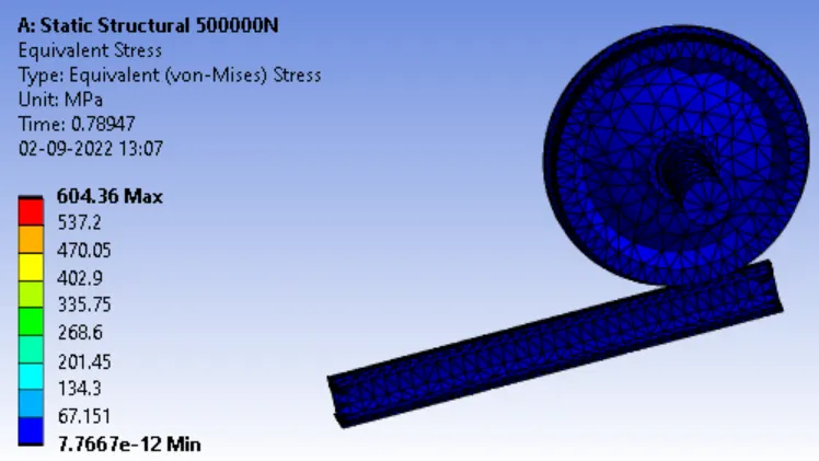
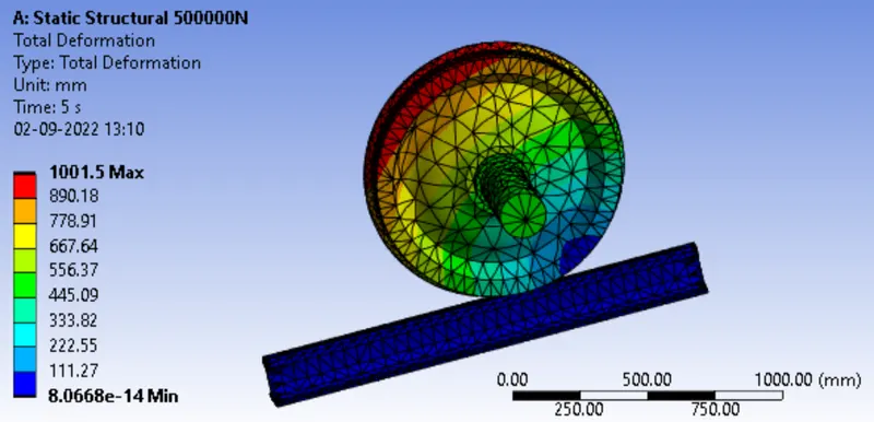
Load 500000N -
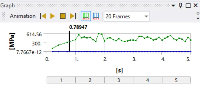
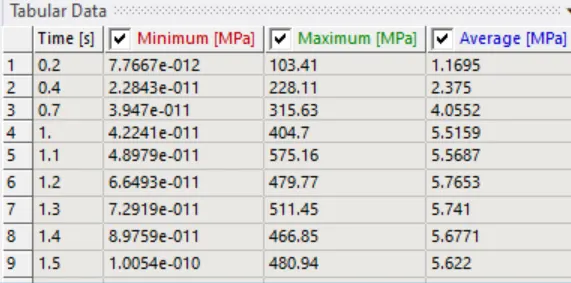
Equivalent Stress -
Total Deformation:
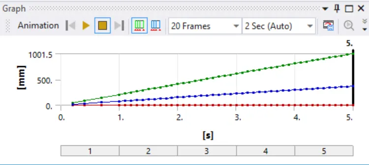
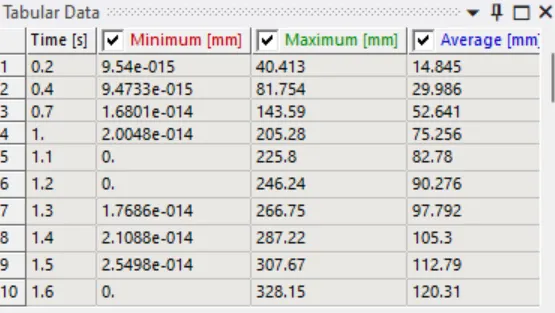
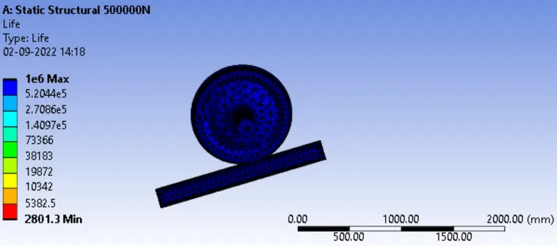
LIFE:
Load 100000N -
Equivalent Stress -
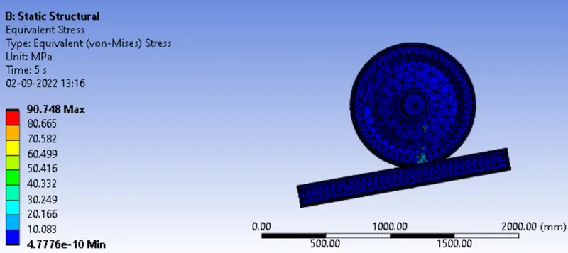
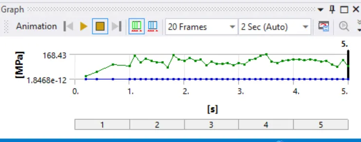
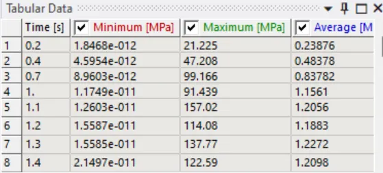
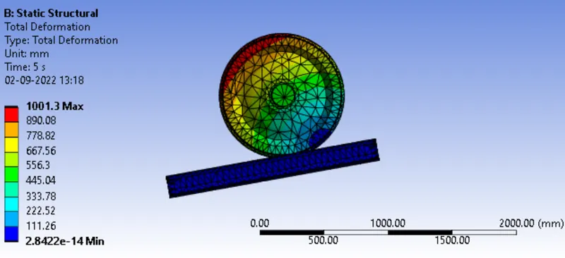
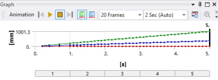
Total Deformation -
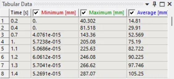
Life:
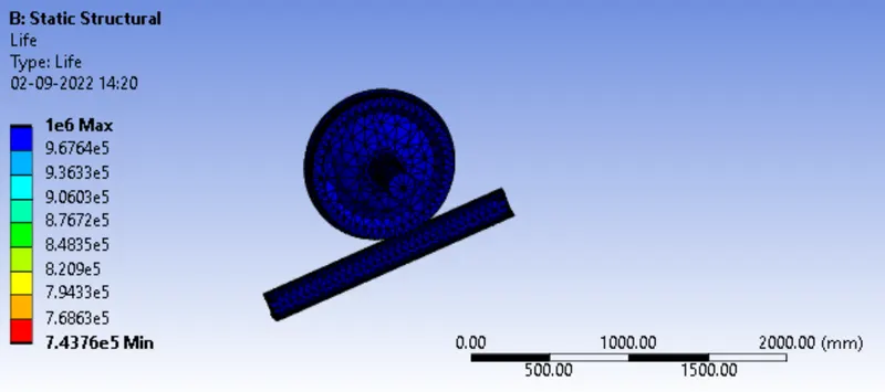
Result:
| S.No | Load |
Equivalent Stress (MPa) |
Total Deformation (mm) |
Life |
| 1 | 500000N | 604.36 | 1001.5 | 1e6 |
| 2 | 100000N | 90.748 | 1001.3 | 1e6 |
Conclusion:
- Equivalent Stress is higher for load of 500000N
- Total deformation is mostly same for both the cases
CASE 2 :
Objective: Implement a User-defined result and calculate the Total Deformation from this result and check if it is the same as that obtained by the inbuilt result by ANSYS for a load of 100000 N.
PROCEDURE:
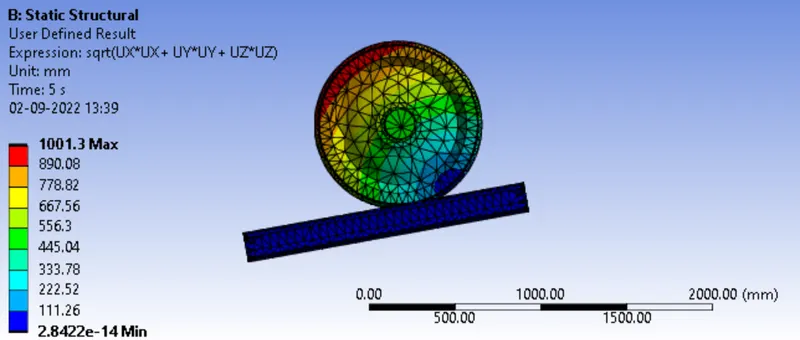
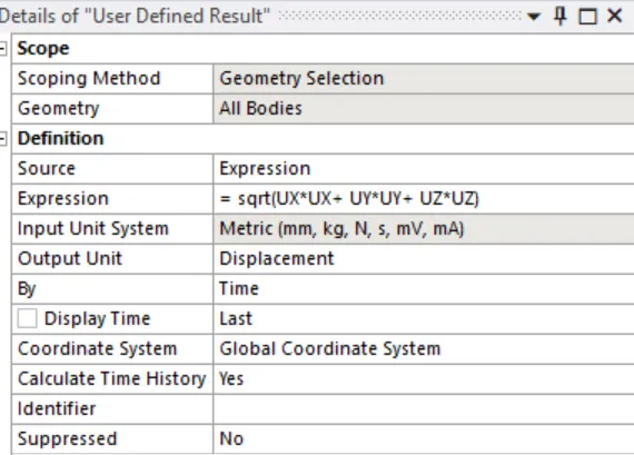
For the user defined we used the Formula - sqrt(UX*UX+ UY*UY+ UZ*UZ) as per the below screenshot
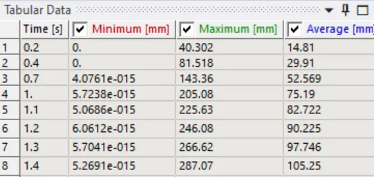
Total Deformation - User Defined result
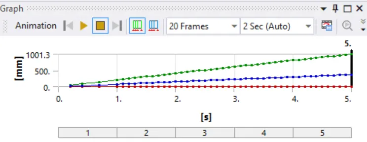
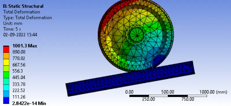
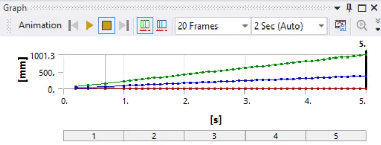
Total Deformation by ANSYS:
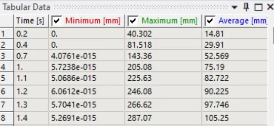
Conclusion:
Total deformation is equal for user defined and Ansys. Total deformation remains same, hence verified.