Week 3 Sheet metal Bending challenge
Objective:
The objective of the following simulation is to perform sheet metal bending analysis in Ansys workbench. Variation in analysis is introduced such as changes in materials, changes in friction coefficient as well as different alloys of same material so as to understand effects of various properties on the results of analysis.
Sheet metal bending:
Metal bending is a process by which metal can be deformed when applying force to the subject, which causes it to bend at an angle and form the anticipated shape, which often results in it being in a ‘V’ or a ‘U’ shape. Usually bending has to overcome both tensile stresses and compressive stresses. When bending is done, the residual stresses cause the material to spring back towards its original position, so the sheet must be over-bent to achieve the proper bend angle. The amount of spring back is dependent on the material, and the type of forming. When sheet metal is bent, it stretches in length.
A press tool is a tool used in order to bend sheet metal and uses a punch and die to do this. Although press braking may seem straight forward, it can be quite difficult to remain accurate throughout the process. There are several types of press tools which deliver different levels of force applied, such as mechanical, pneumatic, hydraulic and CNC to name a few examples.
Types of Metal Bending:
Air Bending:
During this process the work piece comes into contact with the outside edges of the die, as well as the punch tip. The punch is then forced past the top of the die into the V-shaped opening without touching the V.
Bottom Bending:
The difference between air bending and bottom bending is that there is a difference in radius between the two. It differs from coining as the punch and the tie don’t make full contact with the material, and there isn’t enough tonnage to make an imprint into the metal.
Coining:
Coining is a bending process in which the punch and the work piece bottom on the die. This produces a controlled angle, which leads to little spring back. There is more tonnage required on this type of bending than in air bending and bottom bending.
Three point bending:
Three-point bending is a newer process that uses a die with an adjustable-height bottom tool, moved by a servo motor. While three-point bending permits high flexibility and precision, it also entails high costs and there are fewer tools readily available. It is being used mostly in high-value niche markets.
Analysis of sheet metal bending
Step 1: Geometry Creation
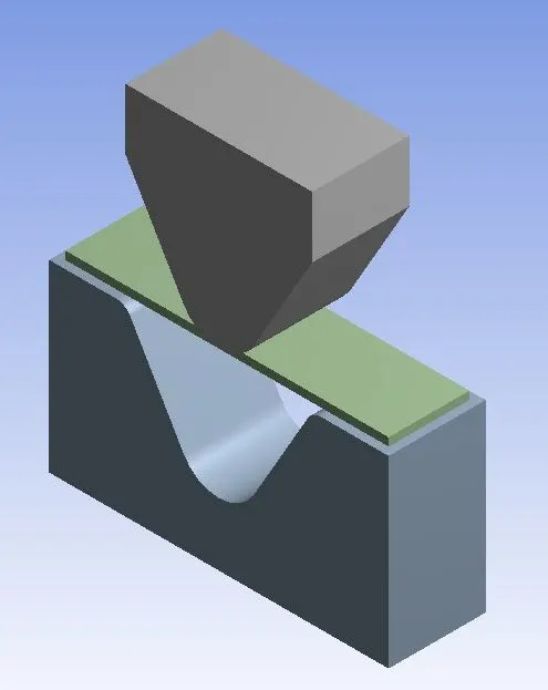
The geometry was imported from the model of bending assembly provided.
Step 2: Material Selection
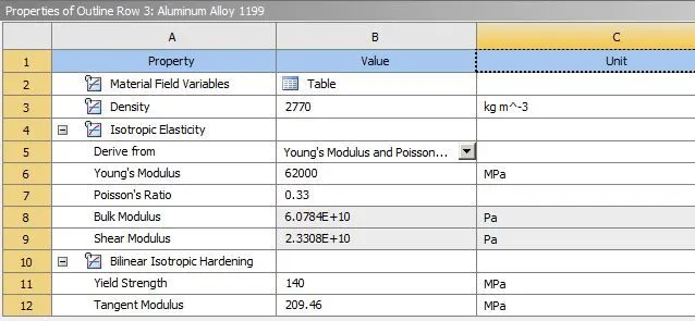
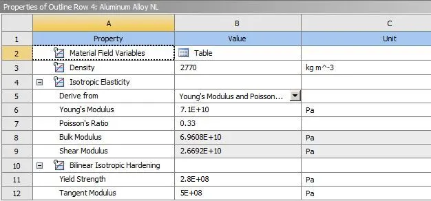
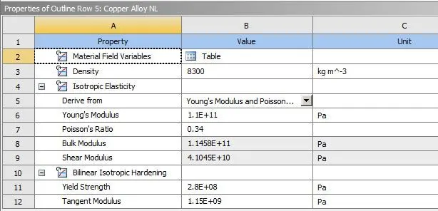
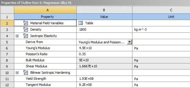
There were a total of 4 materials considered for the sheet metal in this analysis as per the problem statement. The materials are, Alluminium, Al alloy Al-1199, Magnesium and copeer.
Properties for the materials are,
Step 3: Meshing
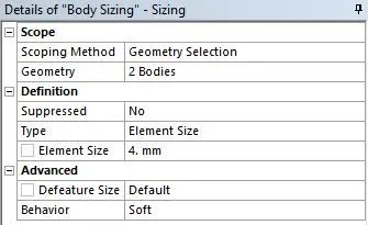
Meshing has been done in this analysis in stages. The parts of components which are not in contact with sheet metal is meshed with a size of 4mm automated mesh.
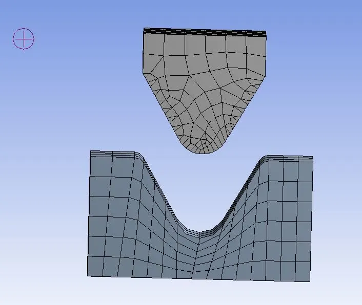
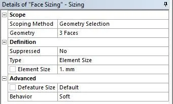
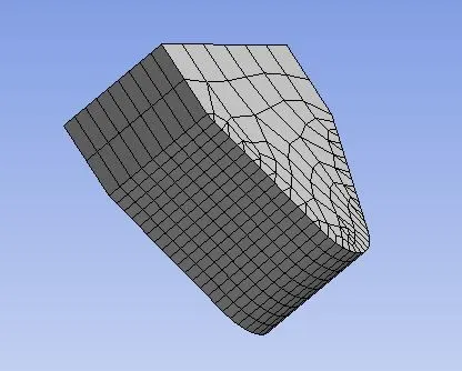
The faces of die and punch which are in contact with sheet metal is meshed with a volumetric mesh of 1 mm.
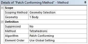
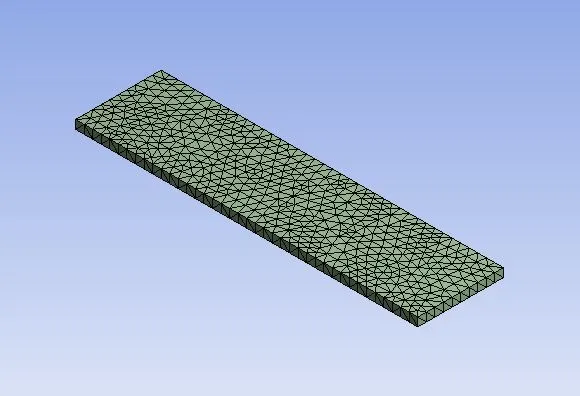
While the sheet metal itself is meshed with a tetrahedron mesh of size 1 mm.
Step 4: Processing
Processing the model involves creation of connections, Joints, Bouindary conditions, Loads etc.
1. Creation of Connections:
Connections created by default were deleted since they only cover surfaces currently in contact. The no. of surfaces of die, punch and sheet in contact with each other increase later on in the analysis, hence default connections do not define the conditions accurately.
Two new connections are defined,
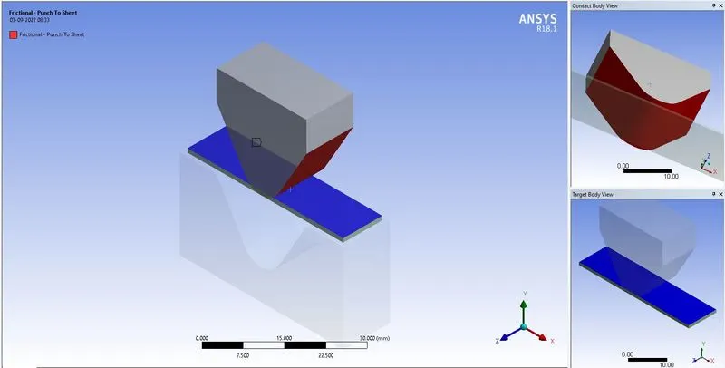
- Punch to sheet connection- The surfaces of punch in contact with the sheet metal is connected to the sheet metal top surface by a friction connection with a friction coefficient of 0.1. Behavior of the connection is changed to 'Autosymmetric' while 'Augmented lagrange' formulation is used to avaoid unnecessary stiffness.Normal stiffness vakuye is inut manually as 0.1 and Interface treatment is set to 'Add offset, no ramping'.
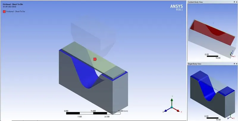
b. Sheet to die connection-The lower surface of the sheet is in contact with the die surfaces, following adjustments were made in order to create a contact btween sheet and the die,
Contact type- friction
Friction coefficient - 0.1
Behavior - Autosymmetric
Formulation - Augmented lagrange
Normal stiffness - Manual
Stifness factor- 0.1
Interface treatment - Add offset, no ramping
2. Analysis settings:
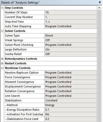
This soluytion is run in 10 steps considering the complexity of the analysis. We can observe the results in between the entire simulation at 10 individual poins and study the changes in the sheet metal. Solver type is kept as 'direct' considering the complexity of the problem.
stabiliztion is updated to 'constant' with energy dissipation ratio as 0.1 to add dampening effect to die and punch elements when they are displaced.
3. Application of loads:
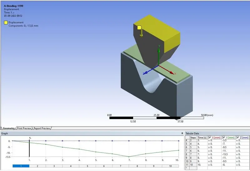
Instead of application of loads, displacement is defined for punch and die in order to simulate bending in order to find out the loads required to bend various metals. The punch is moved down by 13.5 mm downwads in increments of 1.5 mm and then lifted 4 mm to remove itself from contacting the sheet metal.
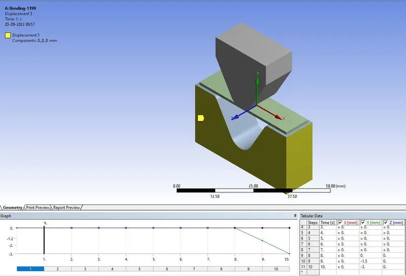
The die is kept constant to bend the shet, onc the bending is complete, the die moved 3 mm downwards to detach from the bending sheet.
The sheet is restricted to move in z-direction in order to keep it in place for bending.
Step 5: Results and Post-Processing
Case 1:Aluminium Alloy 1199, Copper Alloy NL, and Magnesium Alloy NL. Find out the Equivalent stress, Equivalent elastic strain, and Total Deformation in the Y direction and compare the results for the three materials.
Equivalent Stress:
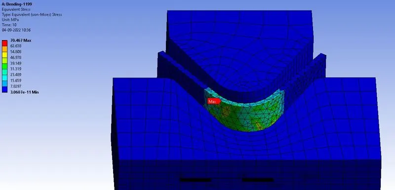
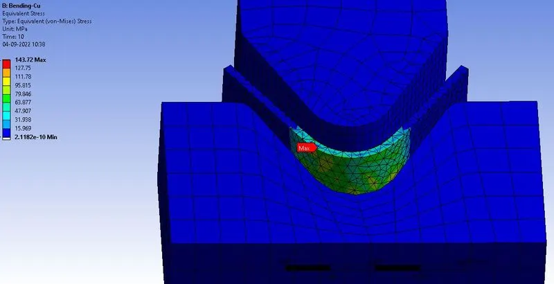
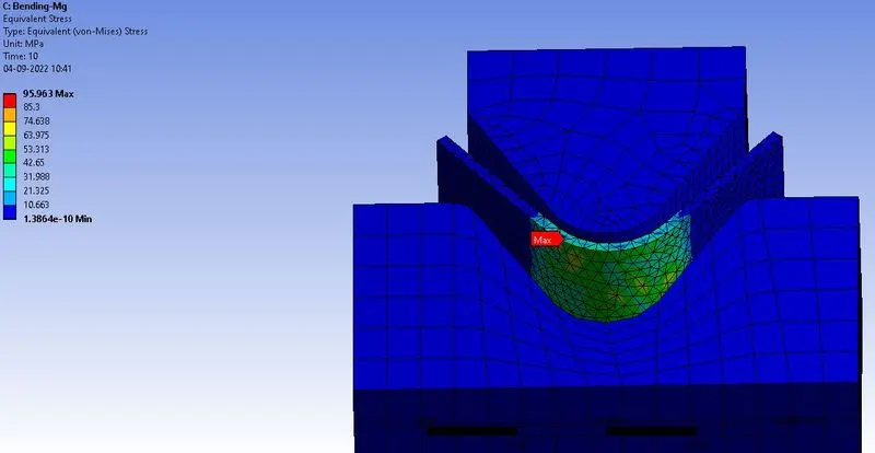
Looking at the stress contour, it is evident that the stress contour is simiar in all three cases and maximum stress occurs the centre of the sheet since maximum bending occurs there.
It can be observed that maximum stress occurs in Cu since it provides maximum resistance to deformation and has the highest youngs modulus of all the three elements in question. Minimum stress can be observed in alluminium alloy-1199 since it has low youngs modulus and has lower flexural strength than Mg.
Equivalent strain:
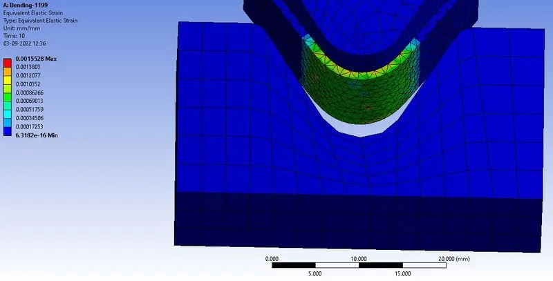
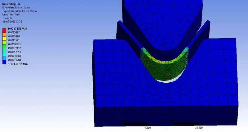
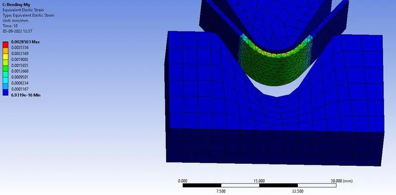
It can be observed that maximum strain occurs in magnesium shet since it has the least youngs modulus. Copper has lower strain than magnesium and is almost as low as that of Al-1199. Al-1199 has the least strain of all lower strength compared to copper.
Directional deformation in Y-axis:
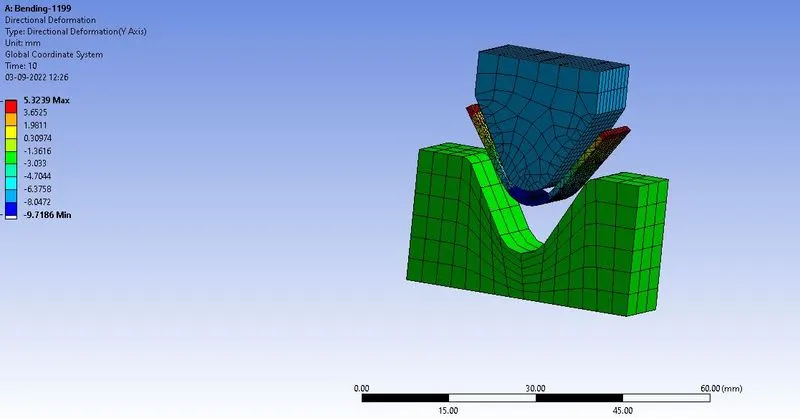
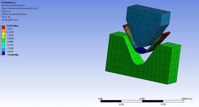
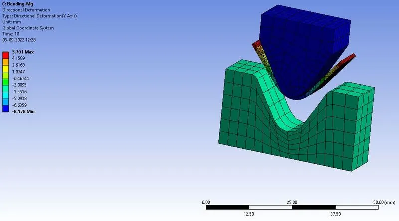
It must be clarifies that all the deformation in this analysis occurs ony in the sheet metal. Any deforamtion shown in the punch and die components in above images are only the retraction from the sheet that they undergo in the end time steps of the analysis.
The deformation in the sheet is almost similar in all three cases since it depends on the die cavity which s the same in all three cases.
Case 2:With the material as Aluminium Alloy, change the friction coefficient to 0.19 and run the analysis as mentioned in Case 1. Compare the results with that in case 1.
Equivalent stresses:
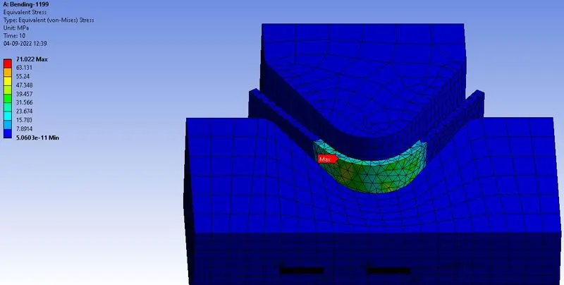
It can be observed that the maximum stress in the Al-1199 sheet increses slightly by ~0.5 MPa from 70.46 MPa to 71.02 MPa.
Equivalent strain:
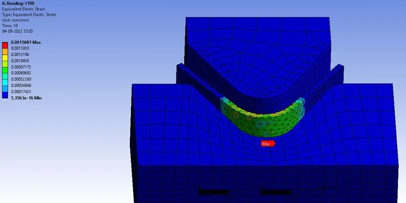
Equivalent strain doesn't seem to change much with a change in coefficient of friction.
Directional deformation in Y-axis:
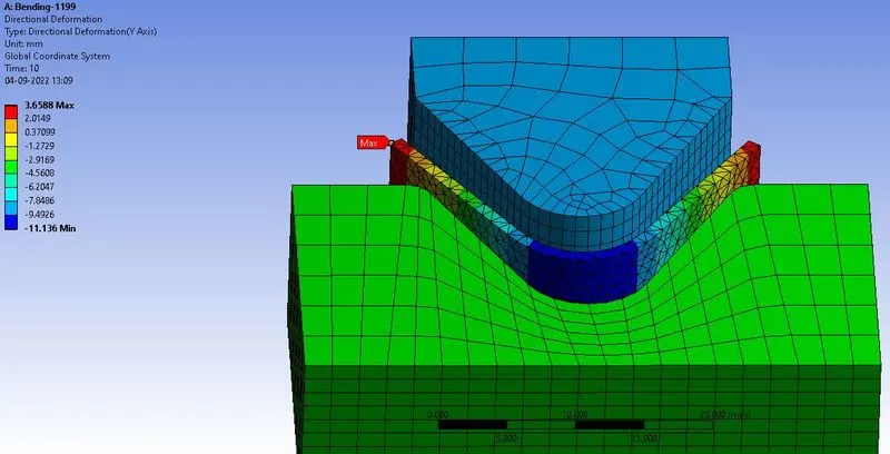
Direct deformation sees a significant change in directional deformaition from 3.66 mm to 5.32 mm as coefficient of friction decdreases from 0.19 to 0.1.
Case 3: Refine the mesh on the plate such that it doesn't cross the academic limit. With Aluminium alloy as material, run the analysis as in Case 1 and compare the results.
The maximum limit for nodes in the academic version of Ansys is 32000 nodes. meshing up to the limit, the element size was updated to 0.7 mm instead of 1 mm in the sheet metal. The resuts obtained are discussed below,
Equivalent stresses:
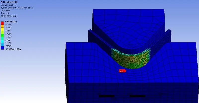
It can bbserved that change in element size of the mesh results in a minute in maz. stress calcuated in the sheet metal. The Max. equivalent stress dropped from 70.07 MPa to 69.8 MPa.
Equivalent strain:
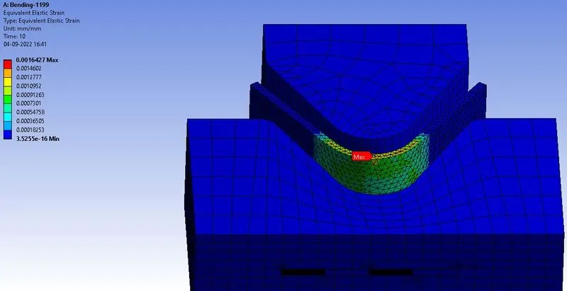
The strain in finer mesh increases by a miniscule amount with finer mesh. The strain increased from 0.00155 to 0.0016.
Directional deformation:
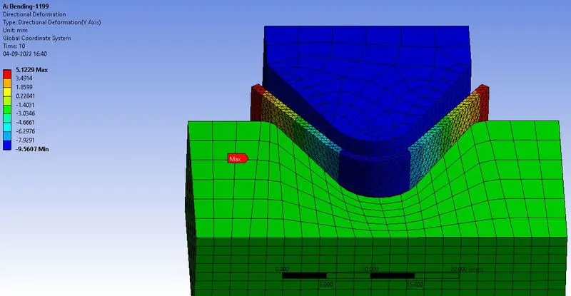
Directional deformation doesn't vary much with finer mesh either. the change is of the order of 0.01 mm only.
Conclusion:
| Results | AL-1199 | Cu | Mg | AL | Al-1199 (µ = 0.19) | Al-1199 (Finer mesh) |
| Equivalent stress | 70.467 | 143.72 | 95.963 | 139.5 | 71.022 | 69.81 |
| Equivalent strain | 0.001553 | 0.00173 | 0.00285 | 0.00264 | 0.00156 | 0.00164 |
| Directional deformation | 5.33 | 3.443 | 5.7 | 6.259 | 3.658 | 5.1229 |
Following conclusions can be made from th above analsysis,
- Maximum stress is bourne by copper whreas maximum strain is observed in magnesium. This means copper is more difficult to bend whereas magnesium bends easily.
- Change in coefficient of friction does not sigificanlty affect the results of the simulation hence, friction does not play a significant role in bending.
- Meshing the model with a finer mesh does not affect the result a lot i.e. mesh size of 1 mm gives sufficient accuracy to the solution of the problem.