Week 3: Flow over a backward facing step
AIM: To simulate flow over a backward facing step in converge.
OBJECTIVE:
- To run the simulation for three different mesh size as 2mm,1.5mm and 1mm respectively.
- To show the plots of velocity,pressure,mass flow rate and Total cell count for all mesh size.
- To show velocity and pressure contours.
INTRODUCTION:
- Backward facing step flow is one representative model for separation flow,widely seen in aerodynamics flows(airfoil,spoiler,high attack angle process),engine flows,condensers,vehicles,heat transfer systems and even flow around buildings etc.
- Backward facing step fow also called as sudden "expansion flows", or diverging channel.
- Backward facing step generally includes an inflow with uniform velocity(laminar or turbulent) from a channel having height 'H',a step on the lower side(or upper side or both sides) with a step height of 'h').
- The flow field of backward facing step is divided into four regions:
- separated shear layer
- The recirculation region under the shear layer.
- Re-attachment region
- attached and recovery region.
- The backward facing step flow happens with large separation vortices in the backward step region and with some small vortex in the corner.
- Between separation bubble and mainstream flow a free shear layer is found,the shear layer develops and form re-attachment on downstream boundary.
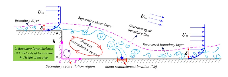
Fig.1 schematic of backward step flow simulation evolution
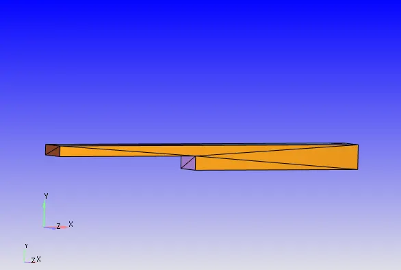
Fig.2 geometry backward facing step
CASE SET UP
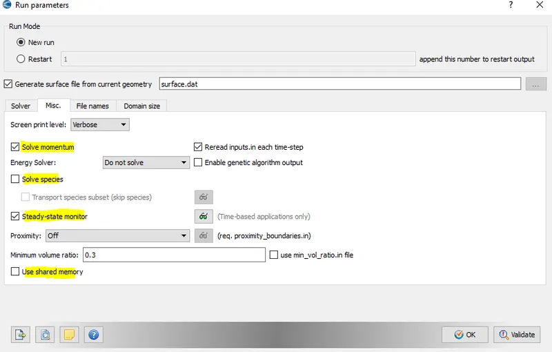
Fig.1 Run parameter set up
- In this set up do uncheck 'solve species' and 'energy solver'.
- steady state moniter should be turned on.
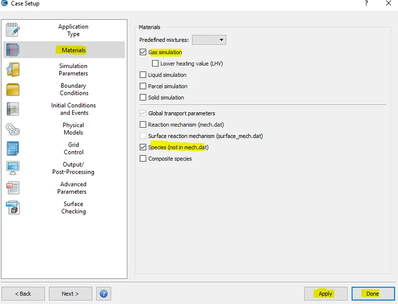
Fig.2
- In material selection ,uncheck reaction mechanism and gas simulation is turned on.
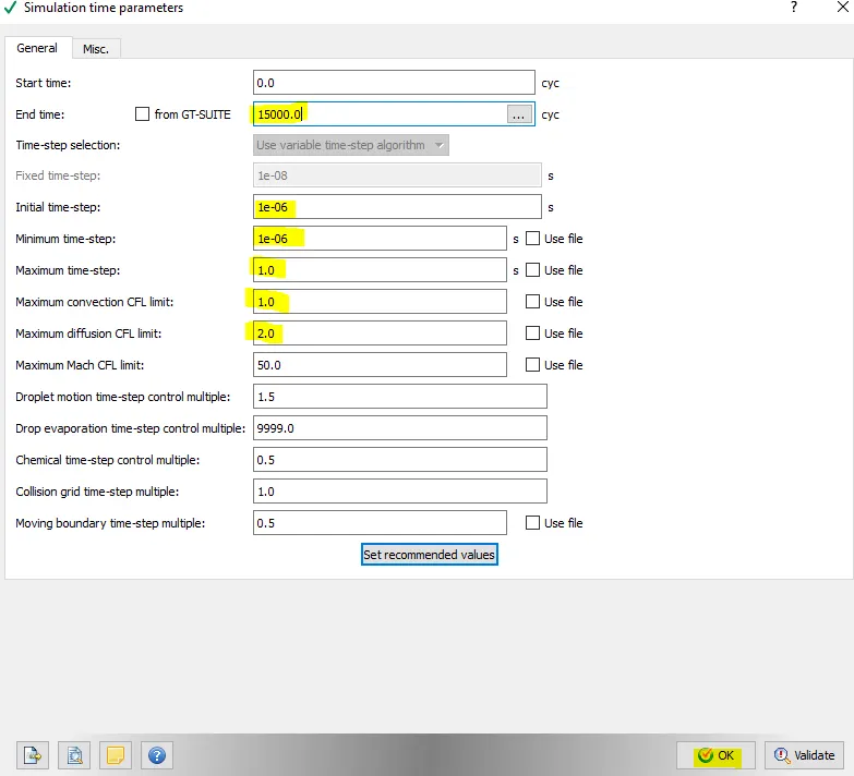
Fig.3 simulation time parameter set up
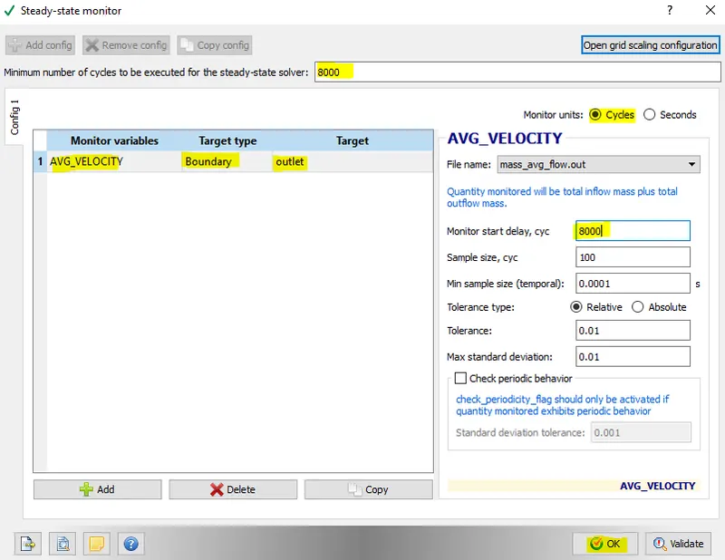
Fig.4
- For steady state solver here the minimum number of cycle is set at 8000 cycles.
- Moniter variable is taken as avg. velocity and target is outlet.
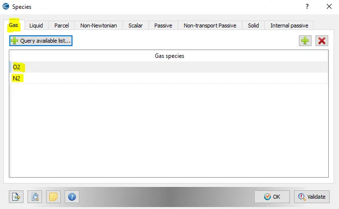
Fig.5
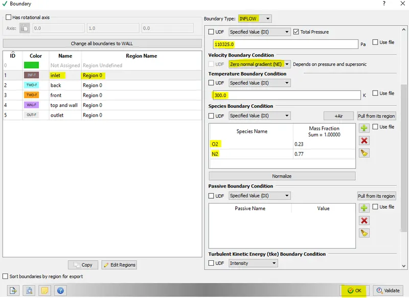
Fig.6 Boundary condition set for inlet
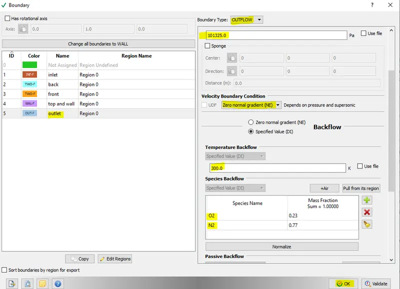
Fig.7 Boundary condition set for outlet
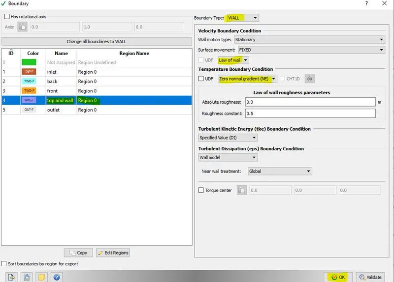
Fig.8 Boundary condition set for top and bottom wall
RESULTS
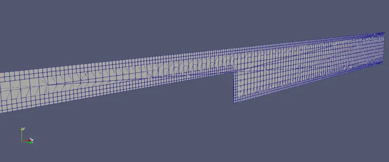
Fig.1 2mm mesh
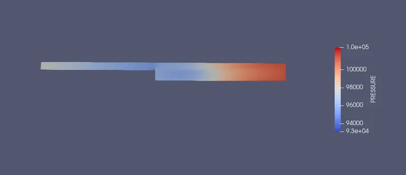
Fig.2 Pressure Contour of 2mm mesh size
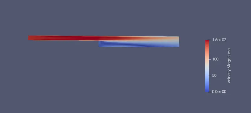
Fig.3 velocity contour of 2mm mesh size
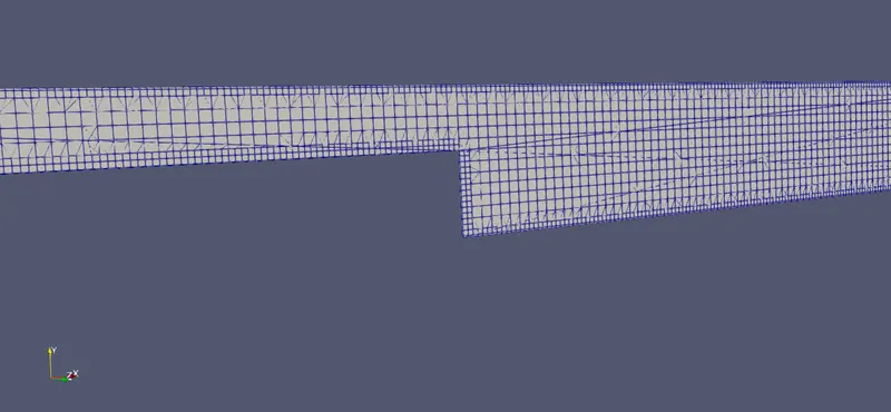
Fig.4 mesh size of 1.5mm
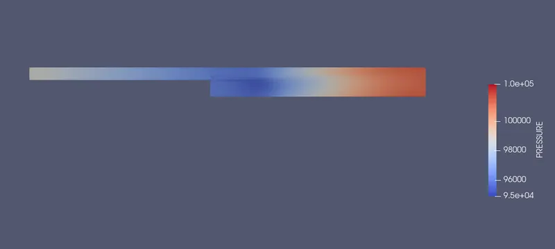
Fig.5 presure contour of mesh size 1.5mm
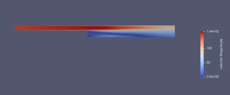
Fig.6 velocity contour of mesh size 1.5mm

Fig.7 mesh size of 1mm
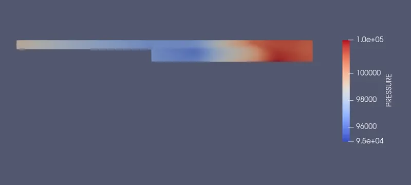
Fig.7 pressure contour of mesh size 1mm
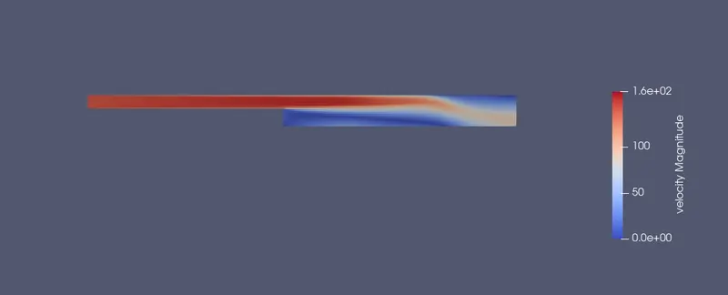
Fig.8 velocity contour of 1mm mesh size
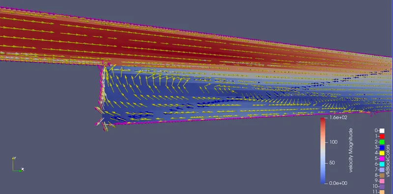
Fig.9 recirculation zone (vortex generation)
- At the backward step region ,vortex is generated and flow separation is taking place.
- It is due to the shear layer formation as the inlet flow dettaches from free surface at the backward step region.
- The boundary layer also disturbs and again conserved at downstream of flow. Due to shear layer, vortex is generated followed by secondary vortex.
PLOTS
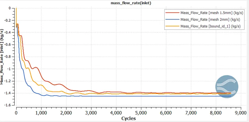
Fig.10 Mass flow rate at inlet
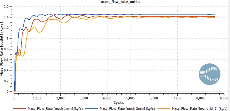
Fig.11 mass flow rate at outlet
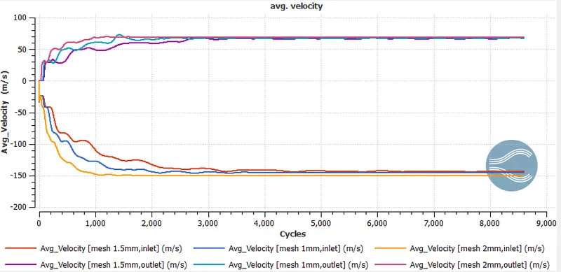
Fig.12 velocity plot for inlet and outlet
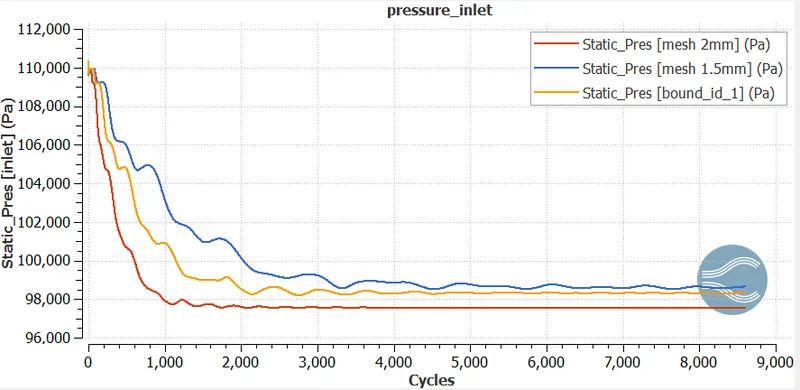
Fig.13
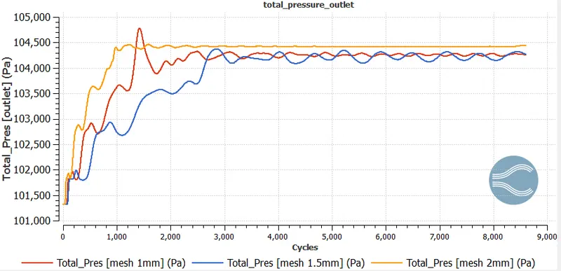
Fig.14
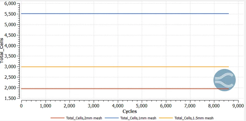
Fig.15
mesh size 2mm
mesh size 1.5mm
mesh size 1mm
CONCLUSION
- The mesh size of 1mm shows the values intermedate between 2mm and 1.5mm mesh size respectively.
- As the cell count increses ,the 1mm mesh size is most probably is good choice.
- The mass flow rate at inlet and outlet is conserved.
- The avg. velocity at inlet is higher than outlet as there is pressure drop inn step region so , vortex generates and velocity at outlet decreases.
- RNG turbulence model is used in this set up case.