Week 3: Flow over a backward facing step
Aim
To simulate the flow over the given backward-facing step geometry using various mesh densities and understand flow separation.
Introduction
Flow separation is a common phenomenon in fluid flows which may be caused due to a sudden change in the geometry or build-up of adverse pressure gradients. Flow separation causes regions of lower pressure which leads to a suction effect that induces flow recirculation. The separated flow can often be seen to reattach to the geometry at a particular distance called the reattachment point.
The backward-facing step geometry can be used to analyze the flow physics of an internal channel flow where the fluid motion is subject to a sudden change in geometry creating flow separation.
Method
Domain and Mesh
The geometry of the backward-facing step was provided and can be seen in the image below.
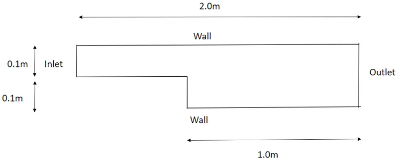
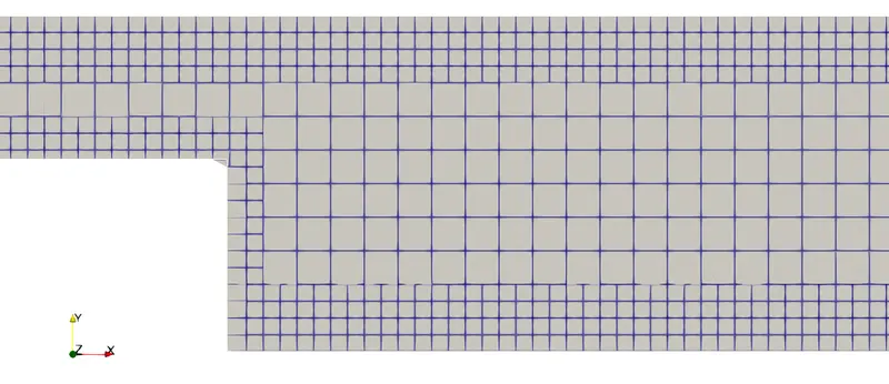
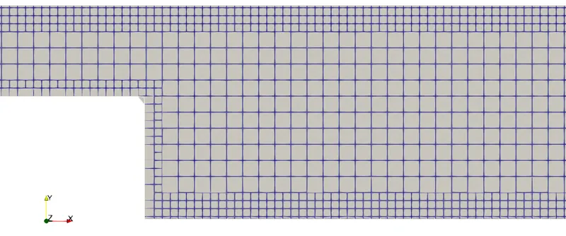
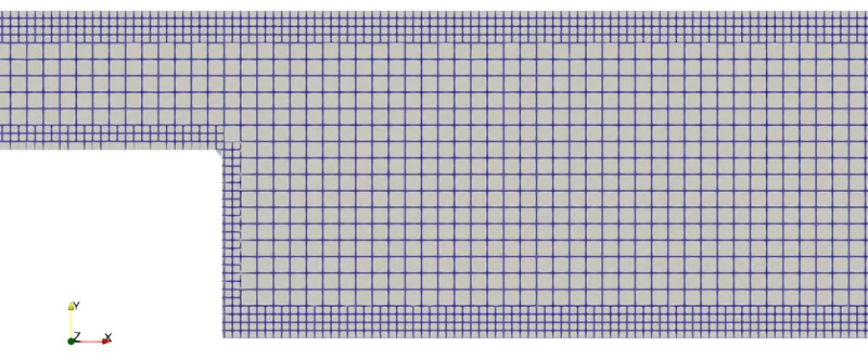
An unstructured cartesian grid was generated over the geometry using two layers of fixed embedding at the walls of the domain. A total of three meshes were generated to observe the changes in the results due to mesh. The element sizings for the three meshes were set to 2e-3m, 1.5e-3m, and 1.2e-3m. The results of the mesh generation can be seen in the images below.
Mesh1 - 2.5k ells
Mesh 2 - 3.8k cells
Mesh 3 - 7.1k cells
CFD Setup
All Simulations were conducted using Converge v3.0. The fluid used in the domain was air with default properties. The pressure at the inlet was set to 110325Pa and the pressure outlet was set to 101325Pa. The top and bottom walls of the channel were set to no-slip condition. The front and back faces of the domain were given the TwoD boundary condition which acts as a form of symmetry.
The steady-state density-based PISO solver was used for the spatial discretization of the flow parameters. Turbulence in the flow was estimated using the two-equation RNG K-Epsilon Model. Momentum, density, turbulence, energy, and species were estimated using the SOR scheme while pressure was estimated using the converge bicgstab scheme.
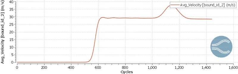
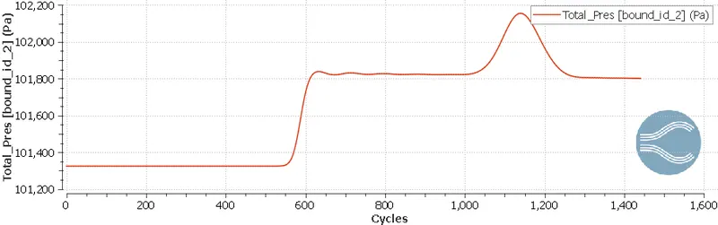
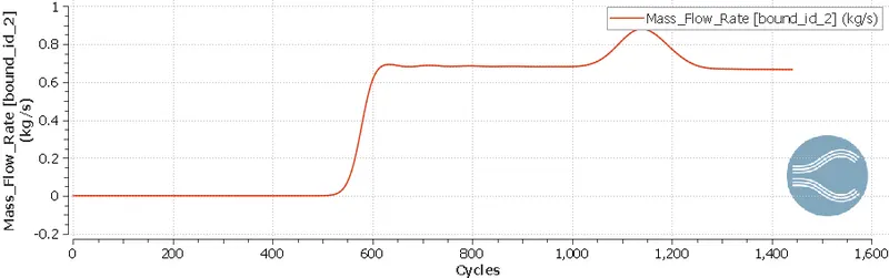
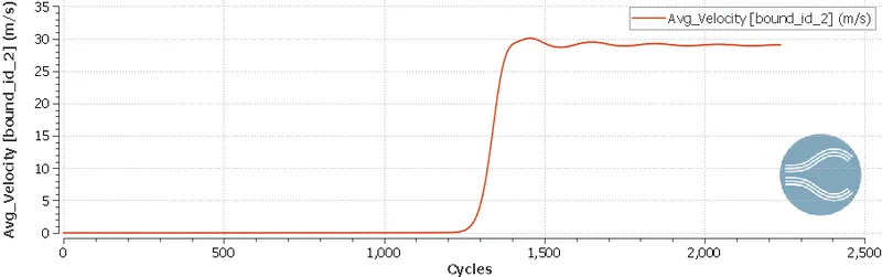
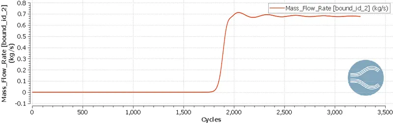
Convergence was monitored using monitors of average velocity, pressure, and mass flow rate at the outlet. The solution was deemed to converge when the monitors varied under 0.001 units across iterations.
Results
The images below show the monitors of velocity, pressure, and mass flow rate at the outlet to ensure convergence of Mesh 1.
The images below show the monitors of velocity, pressure, and mass flow rate at the outlet to ensure convergence of Mesh 2.
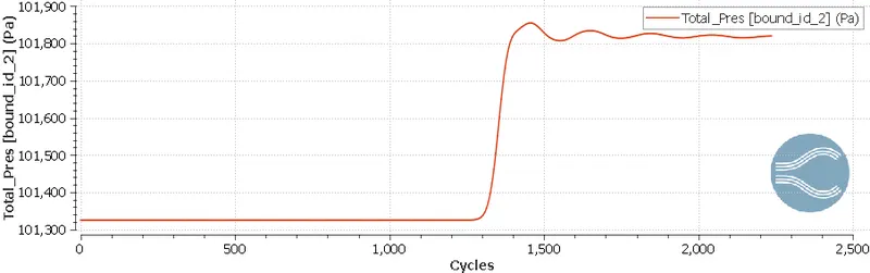
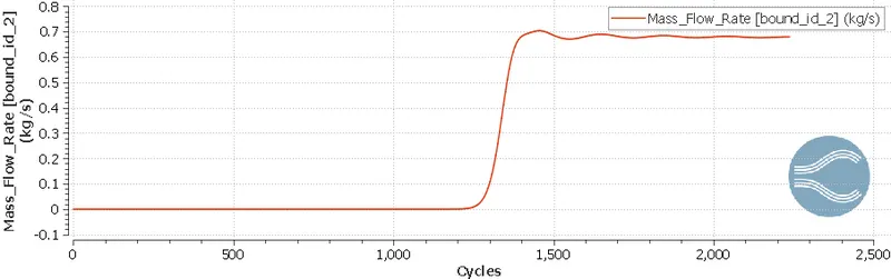
The images below show the monitors of velocity, pressure, and mass flow rate at the outlet to ensure convergence of Mesh 3.
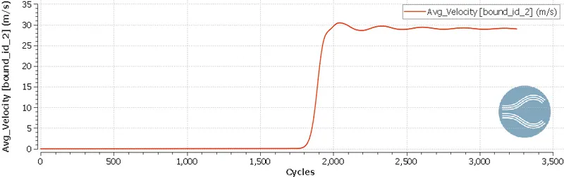
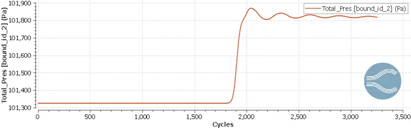
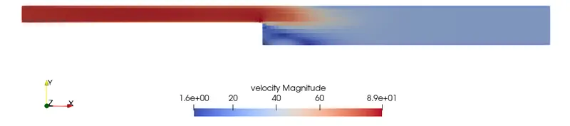
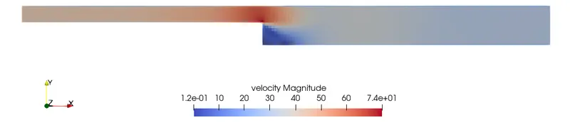
The images below show the comparison of the velocity contour for the various meshes.
Mesh 1
Mesh 2
Mesh 3
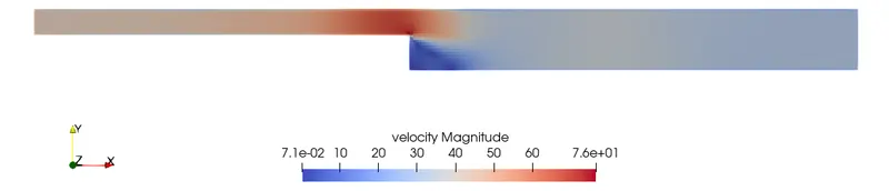
From the velocity contours, a region of low velocity can be seen consistently at the start of the step. This decrease in velocity can be attributed to the flow separation and recirculation of flow occurring at the step. It can also be seen that there is an increased velocity prediction in Mesh 1.
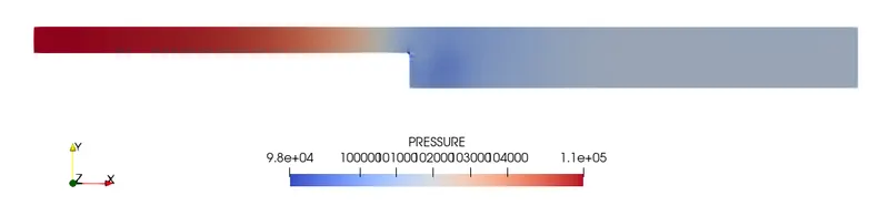
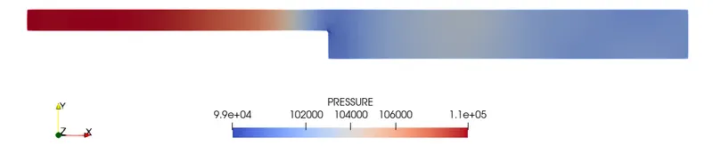
The images below show the comparison of the pressure contour for the various meshes.
Mesh 1
Mesh 2
Mesh 3
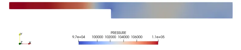
There aren't any significant changes in the pressure contours between the three meshes. A consistent drop in pressure can be observed at the start of the step for all the meshes. This can be attributed to the occurrence of flow separation as evidenced by the velocity contours.
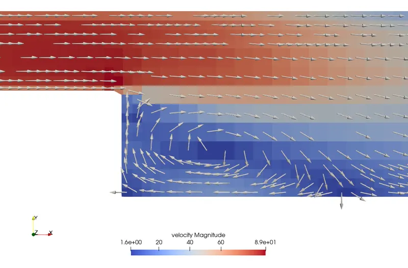
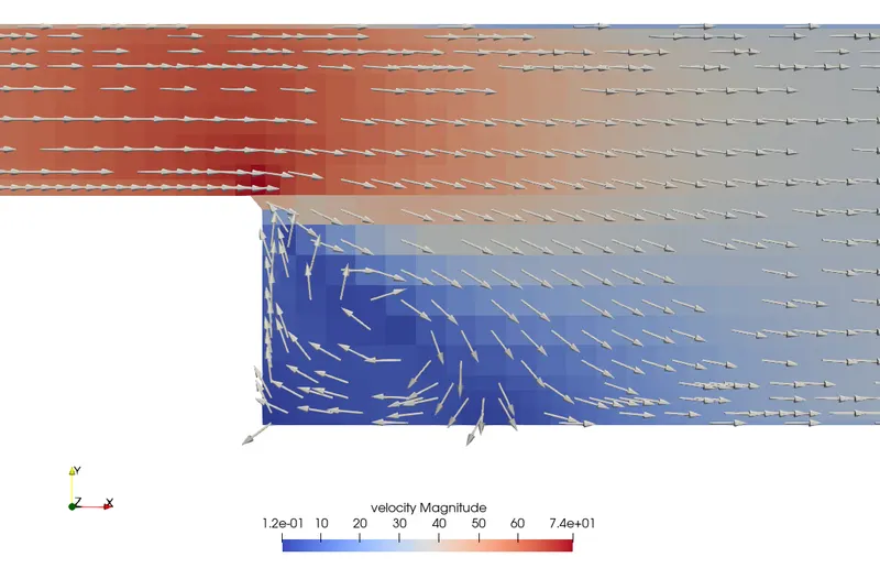
The images below show the comparison of the velocity vectors for the various meshes to understand the flow separation region.
Mesh 1
Mesh 2
Mesh 3
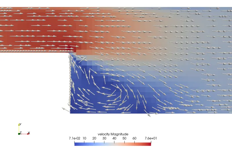
All mesh cases show a well-defined region of low-velocity flow recirculation at the start of the step. Reattachment of the flow can be seen to occur downstream of the step where the velocity vectors regain their parallel nature with the respect to the walls of the channel. It can be seen that Mesh 1 predicts a larger region of flow separation compared to the refined mesh cases. This large region could be due to the higher velocity prediction in the flow.
Conclusion
Simulations of airflow over the given backward-facing step geometry were conducted using converge. The analysis was conducted over three meshes of varying densities. Significant flow separation and reattachment were observed in all the mesh cases. The coarse mesh was observed to predict a higher velocity and larger recirculation region compared to the refined mesh cases.