Week 3: Flow over a backward facing step
OBJECTIVE:
We are to simulate flow over a backwards-facing step for the following three mesh sizes:
- dx = dy = dz =2e-3 m
- dx = dy = dz =1.5e-3 m
- dx = dy = dz =1.0e-3 m
INTRODUCTION:
Backward-facing step is one of the standard problems in CFD. It is a representative model for flow separation study and is crucially important not only in aerodynamic flows but in engine flows, flows around buildings etc.
Flow Separation: Flow Separation is an essential phenomenon in fluid dynamics, where the boundary layer detaches from the surface into wake.
It is essential to study flow separation as it can lead to flow losses, vortex formation, stall effects and undesirable vibrations.
CASE SETUP:
Geometry:
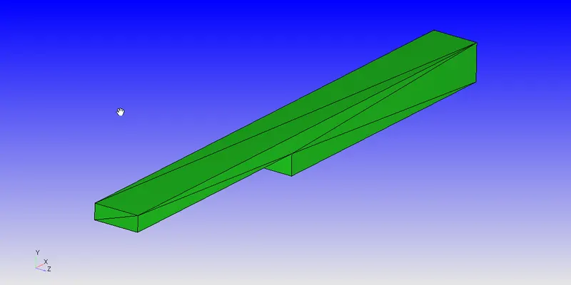
We have the following geometry of a standard backwards-facing step:
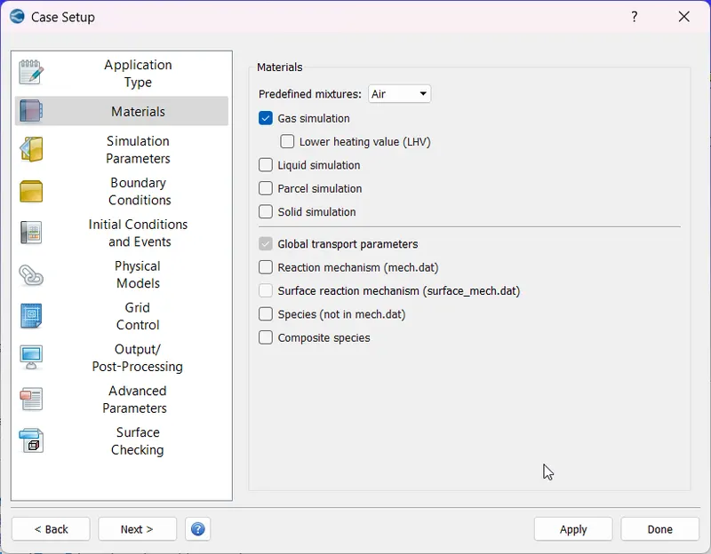
We will be setting up a time-based simulation with air as our working fluid:
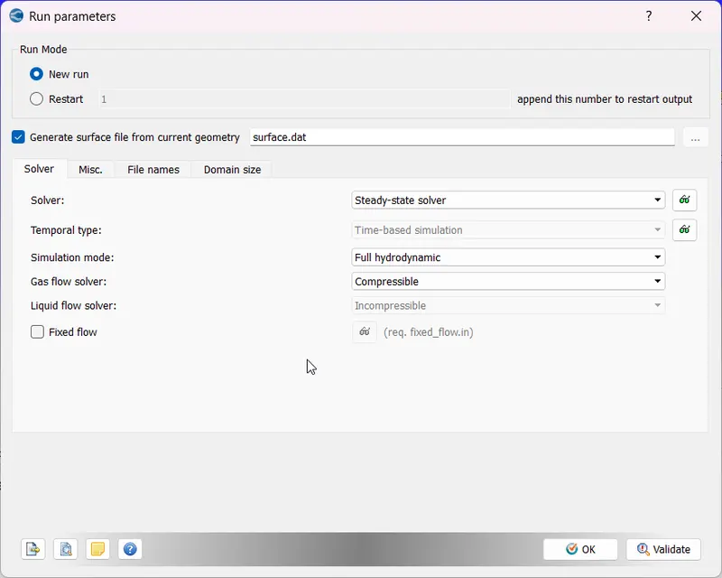
The solver we will be using is a steady-state compressible solver, and since the problem is simple, we will directly go for a full-hydrodynamic solution:
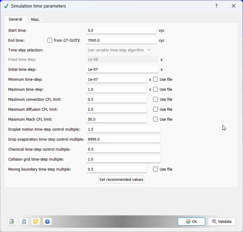
Following is the setting for the time-step and a maximum number of cycles for simulations:
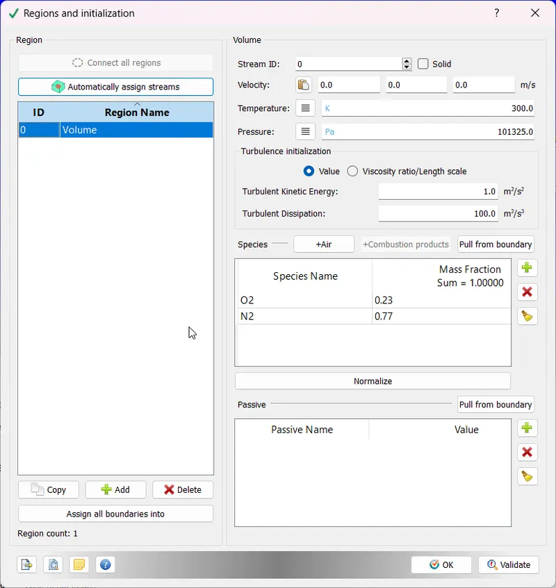
Assigning Volume Region to the model:
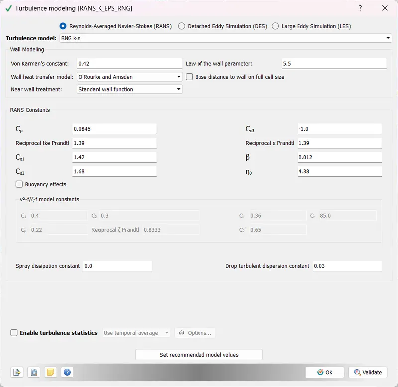
We will be using K epsilon RNG model with default settings:
Next, we will assign boundary conditions:
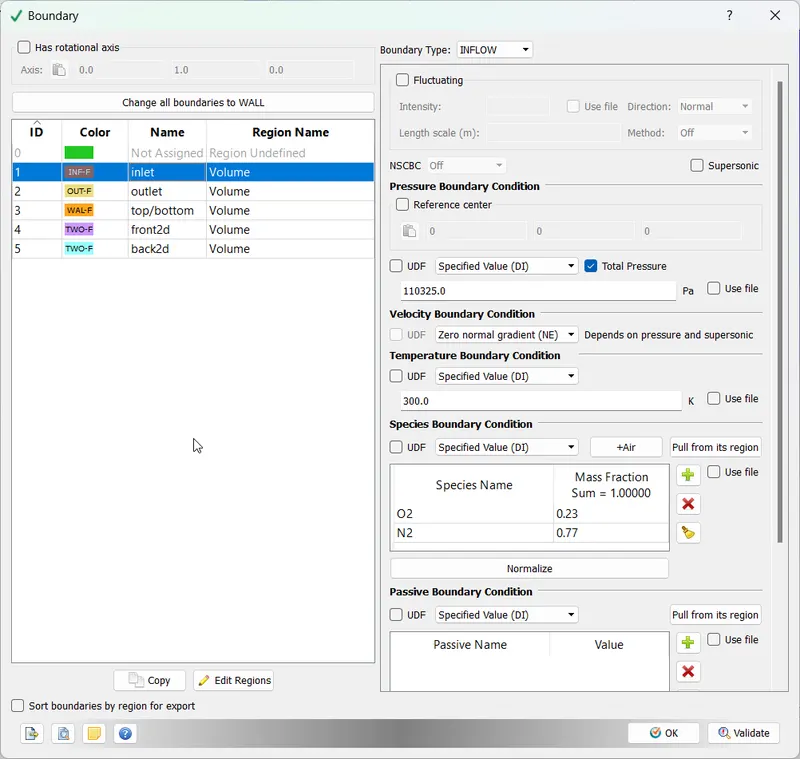
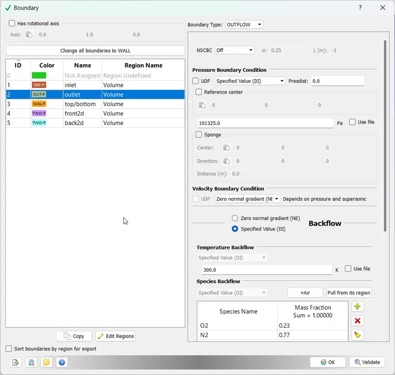
Boundary 3 we will assign as a simple no-slip wall. Boundaries 4 and 5 are set as 2D.
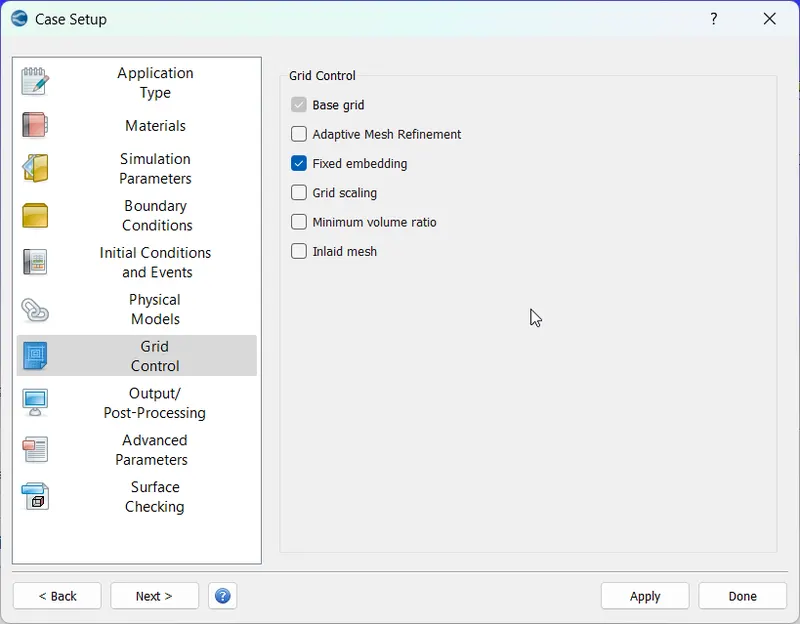
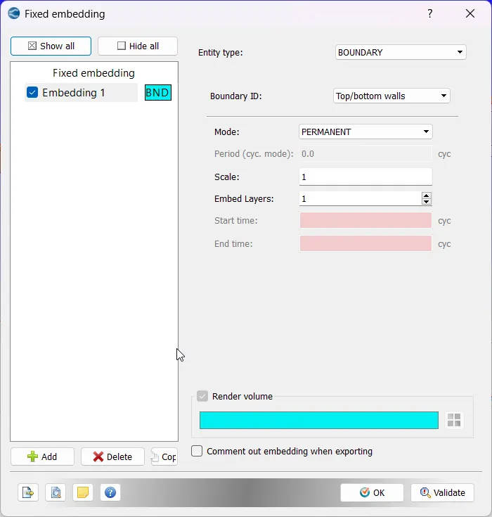
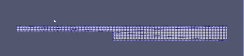
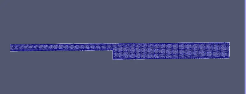
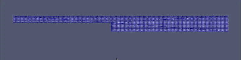
We will work on three mesh sizes, but for each, we will create an embedding that refines the mesh near the assigned boundary. In this case, we will make the embedding for the top/bottom walls:
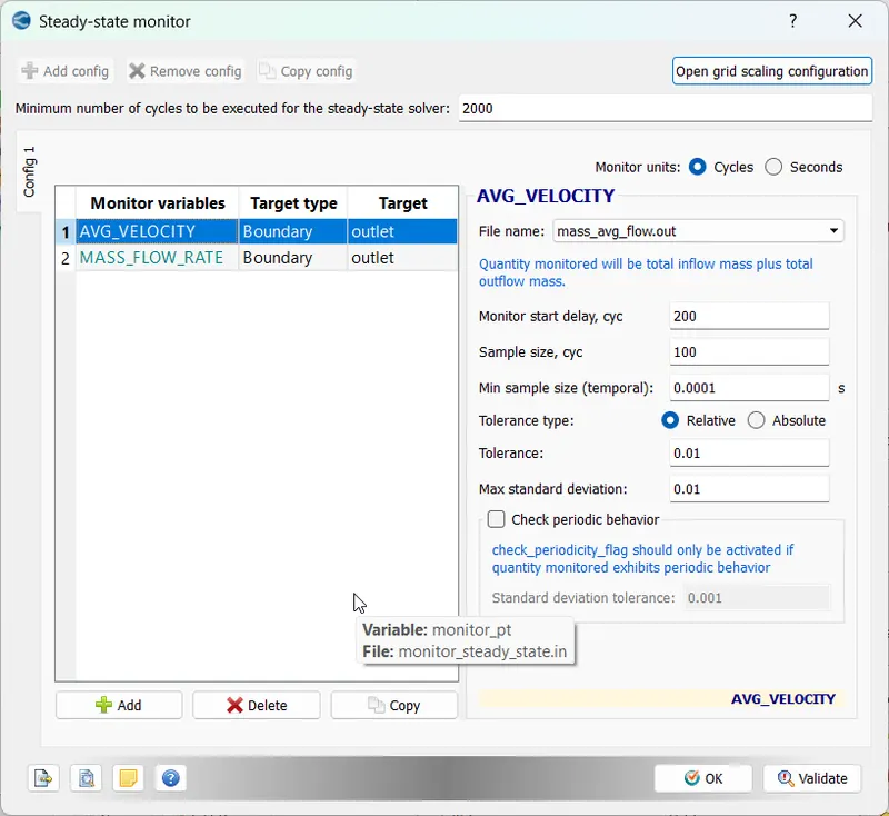
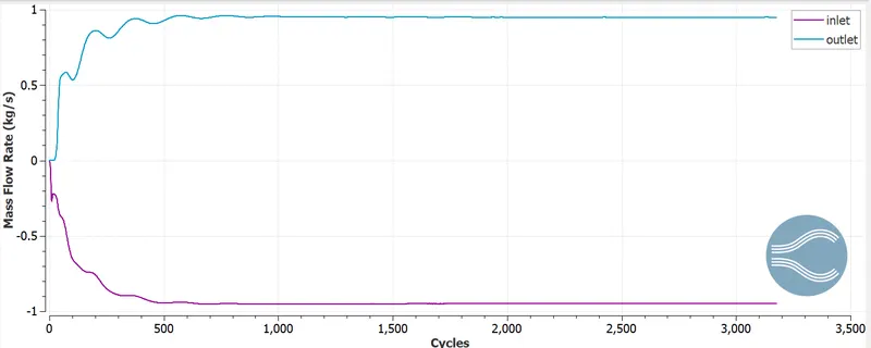
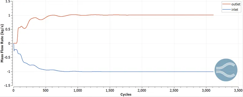
Through the steady-state monitor, we will define the convergence criterion to stop the simulation and the minimum number of cycles after which convergence criteria should be applied. In our case, we are using velocity and mass flow rate:
Everything else we leave as default.
RESULTS:
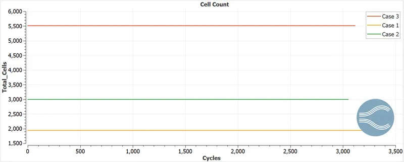
Cell count for each case:
CASE I (2 mm):
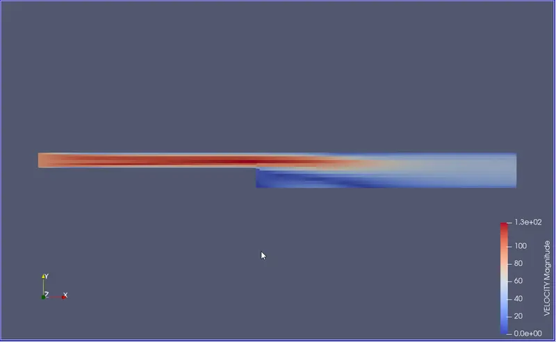
Velocity Contour:
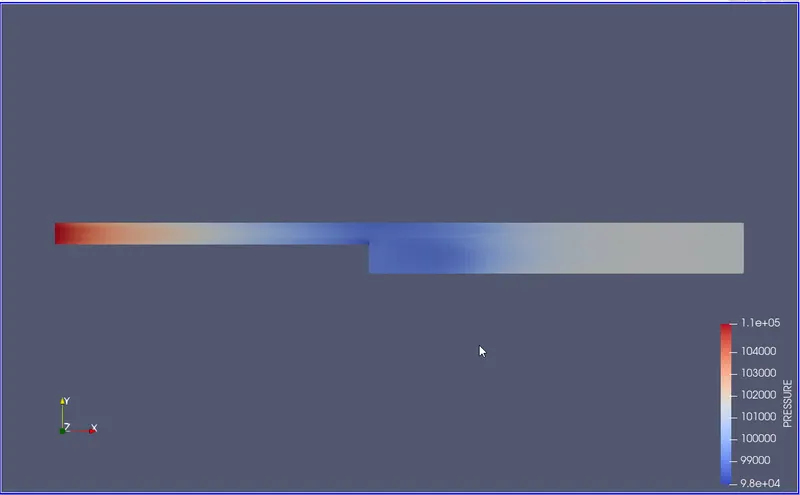
Pressure Contour:
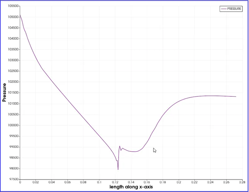
Pressure Plot:
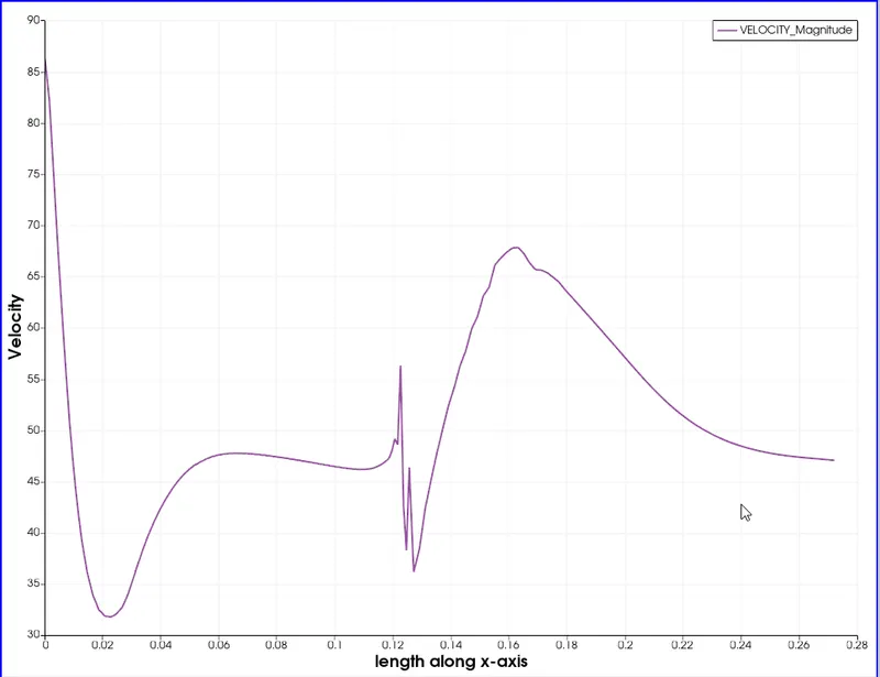
Velocity Plot:
Mass Flow Rate:
Animation:
CASE 2 (1.5 mm):
Velocity Contour:
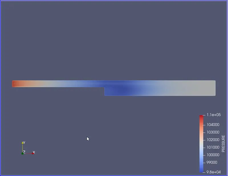
Pressure Contour:
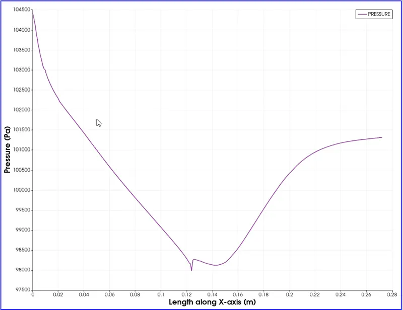
Pressure Plot:
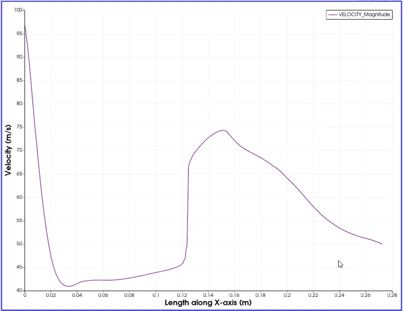
Velocity Plot:
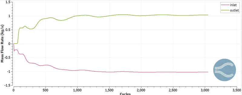
Mass Flow Rate:
Animation:
CASE 3 (1 mm):
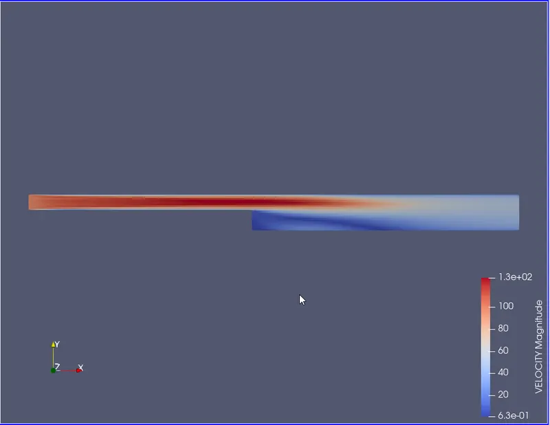
Velocity Contour:
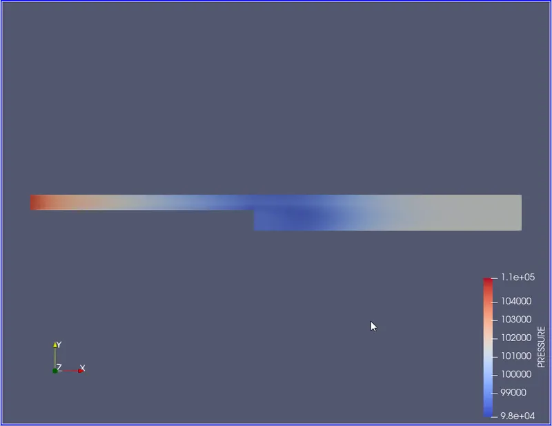
Pressure Contour:
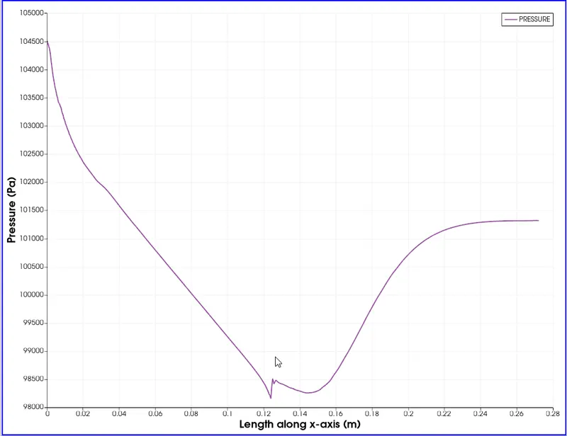
Pressure Plot:
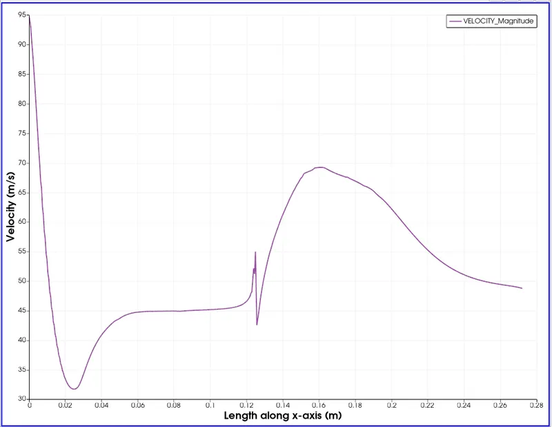
Velocity Plot:
Mass Flow Rate:
Animation:
Recirculation Region:
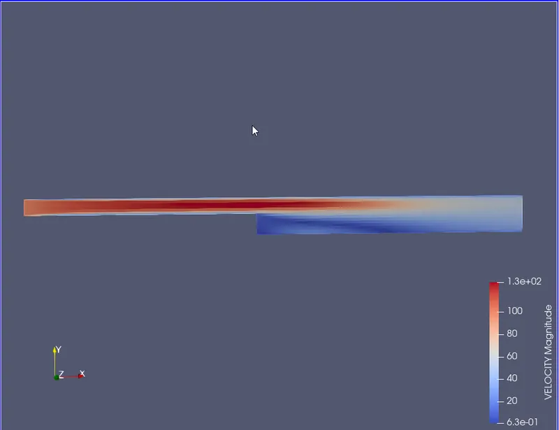
Due to sudden pressure drop caused by separation, turbulence and vortex formation occurs, which creates a region of recirculation near the step:
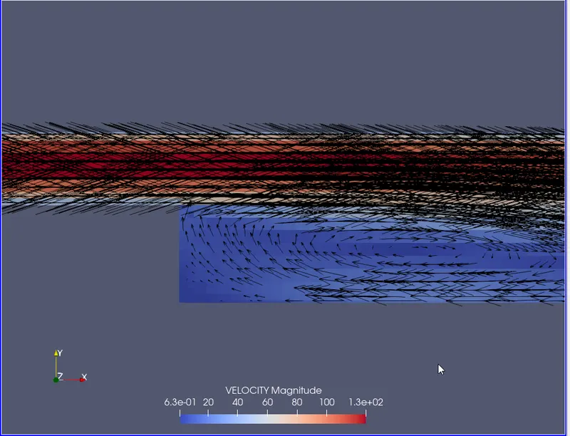
Cause of Separation:
Separation occurs as the fluid flowing along the narrow section encounters an adverse pressure gradient as the fluid suddenly expands into the broader section.
CONCLUSION:
- We can see flow separation at the edge of the step in the velocity contour for all three cases, the difference being the separation has higher resolution in later cases due to a more refined mesh.
- This phenomenon is also backed by a significant drop near the step shown in pressure contours and the abnormal curves in velocity and pressure plots near the location of the step.
- The separation of flow causes the formation of eddies and vortexes, as shown in the recirculation region above, which is responsible for flow losses.