Week 3 - External flow simulation over an Ahmed body.
Objective :- To simulate the External flow over an Ahmed body
Ahmed's body and its importance ?
The external surface of the car is very important in aerodynamics aspects of vehicles such as stability, comfort and fuel consumption at high speeds. The total weight and modification of the external surfaces of the car are the most important to improve the aerodynamics characteristics of the car. These characteristics are helpful to improve the cruising conditions, greater stability of navigation, and lower fuel consumption.Aerodynamics analysis is used in the design of car to
reduce drag coefficient. The investigation has obtained the behaviour of newly developed turbulence models for complex
geometry cases, a simplified car model, known as the Ahmed body,was originally created by S. R. Ahmed in 1984.
The Ahmed body represents a simplified, ground vehicle geometry of a bluff body type. Its shape is simple enough to allow for accurate flow simulation but retains some important practical features relevant to automobile bodies,commonly used as test case in Industries. An important advantage in CFD analysis of Ahmed body is Validation,as there are numerious experimental analysis being done on ahmed body.
The wake separation flow behind the Ahmed body is the main contributor to the drag force, accurate prediction of the separation process and the wake flow are the key to the successful CFD modelling.
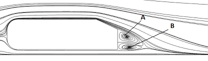
The A-recirculation region that is formed as the flow separates at the top of the vertical back surface of the model. B-recirculation region that is formed due to the separation at the base of the model.
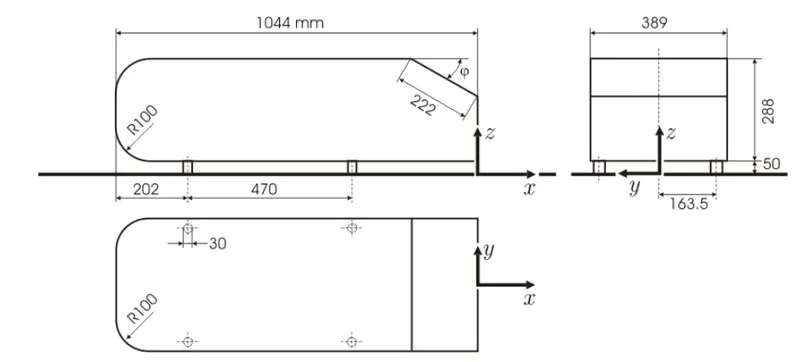
The wake was shown to be highly dependent on slant angle.`(phi)` For slant angles less than 12°, the flow remains attached over the the slant. The flow is essentially two-dimensional and has low drag. Between 12° and 30° the flow becomes much more three-dimensional as the c-pillar vortices form. These reach maximum strength at 30°. The drag increases significantly as the low pressure cores act on the rear surfaces. Past 30° the flow separates fully off the slant. This results in a sudden decrease in drag.
Solution :-
Geometry :
The Ahmed body is made up of a round front part, a moveable slant plane placed at back part of the body to study the coefficient of drag and separation phenomena at different angles, and a rectangular box, which connects the front part and the rear slant plane.
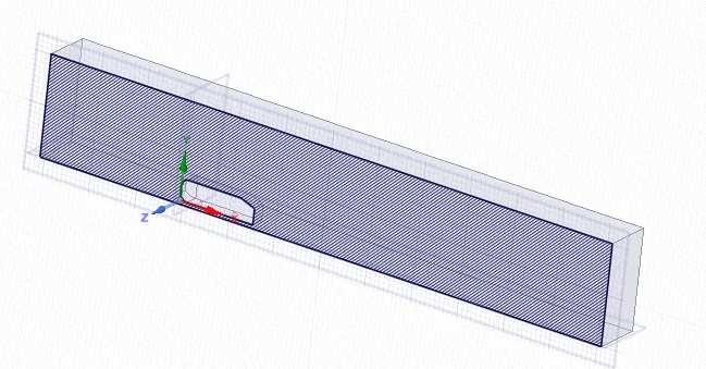
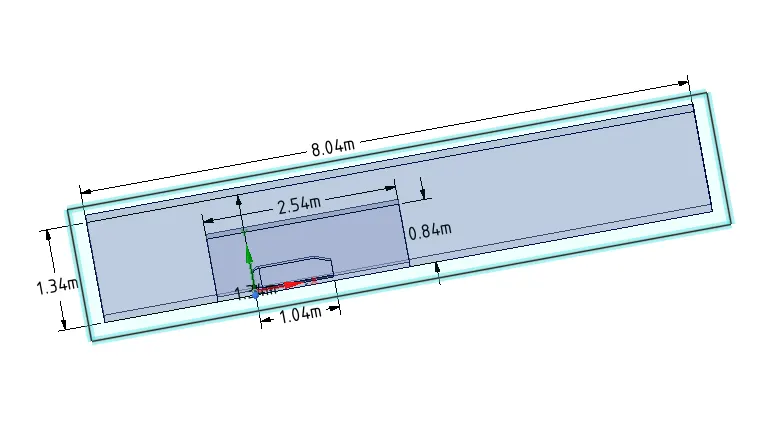
Model is cut along symmetric Y-plane are below dimensions.
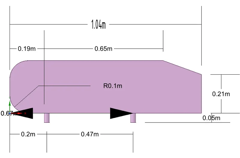
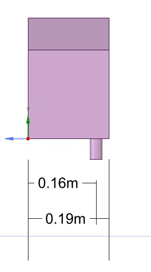
Split body - Ahmed body is simulated in a 2D space with appropriate dimension using Enclouse tool and splitted along Y-plane to reduce computational time,as the body is symmetric along the plane.
Setup :
- Pressure based solver is used,as fluid flow is an turbulent incompressible flow. (Default material - air)
- Solution method utilizes pressure-velocity coupling - SIMPLE scheme as coupled with gradient- least square cell based method, pressure as second order and setting momentum as second order upwind, turbulence kinetic energy & turbulence dissipation as first order upwind.
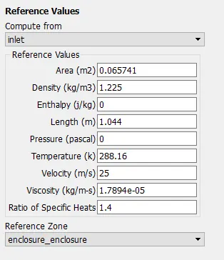
- Projected area is directly obtained from fluent report tool in the results section. (0.065741`m^2`)
- For reference, solution is computed from Inlet & Length along the flow direction is provided (1.044m)
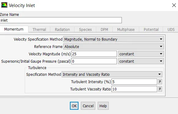
- BC Input : Velocity Inlet = 25m/s & 0 guage pressure outlet.
Modified low RE model like K-omega SST will perform well in the area close to the wall,as we are intersted in analysing the external goemetry
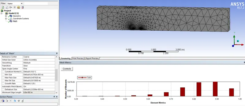
Case 1a : K-Omega SST Model - Default Mesh
Default Coarse Mesh of size 0.4m was only applied in first case.
Results -
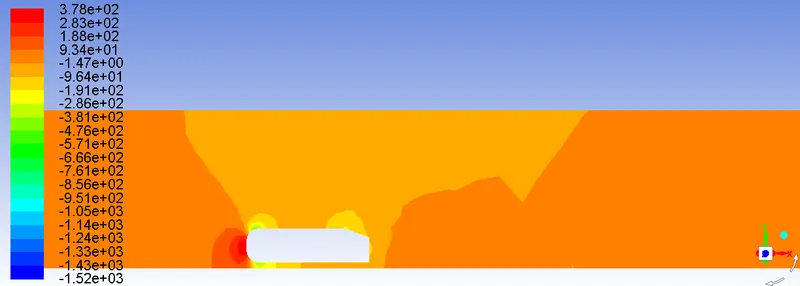
Pressure
Velocity
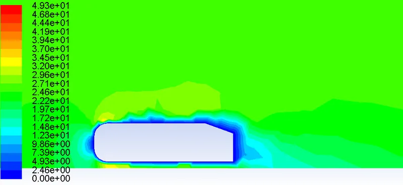
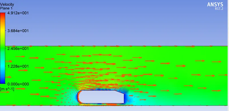
- As we can see from the above results is of no expected output, where no proper wake has formation at all.
- Even the velocity vectors behind the body is pointing straight along the flow direction, without any rotation/reverse in direction.
Case 1b : K-Omega SST Model - Refined Mesh
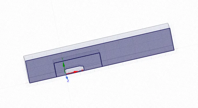
Based on the above results will further refined mesh by adding another enclosure which can accomodates all the flow physics around Ahmed body. A finer mesh will be appiled in this Inner enclosure.
Interefence - The overlapping/ Interefence formed in the goemetry b/w two encloures is fixed in space claim Interference tool.
Shared Topology - In oder to have single entity flow domain body with different mesh size & shape , shared topology is selected for whole FFF enclosure properties.This results in an unfiorm mesh link b/w tetrahedral and hexahedral cells in the adjoining face regions of both boxes.
Inflation:
- It is very important to have optimum quality of mesh near the wall to capture the accurate simulation of flowfield.
- With medium-fine mesh size, Inflation was applied at car wall to obtain accurate simulation of flowfield, Y+ size was figured out for K-Omega SST model.
Wall treatment :- In order to obtain full resolution near the wall, The first cell lies at most at the boundary of the laminar sub-layer and no further. Here, y+ value is 1 or below. But most common practise & optimum results are shown when Y+ is b/w 1 to 5.
Y+ = 1 Y+ = 3
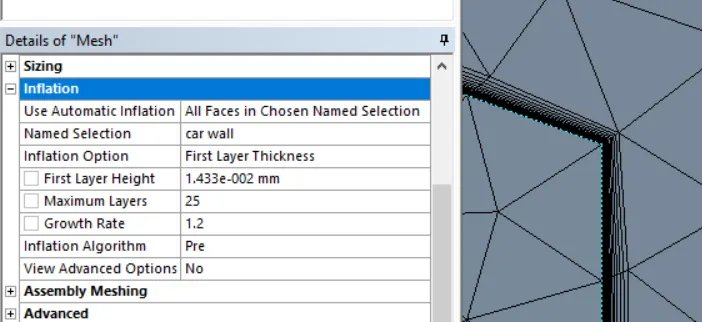
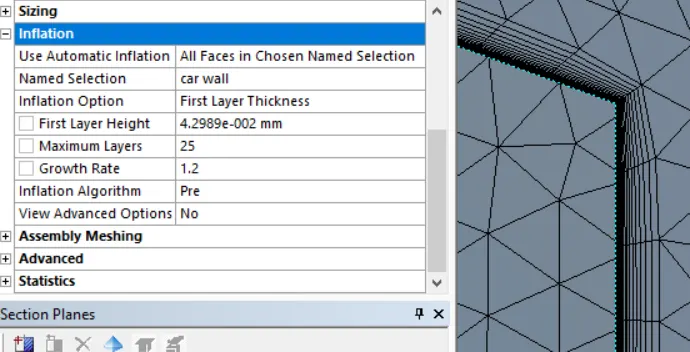
Y+ = 5 Y+ = 10
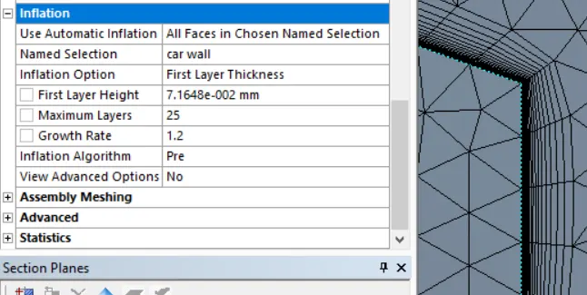
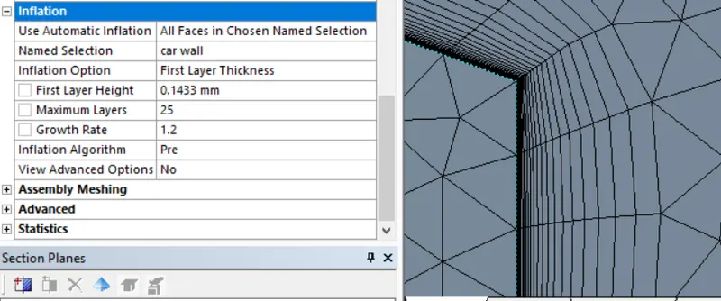
Using Y+calculator
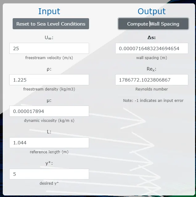
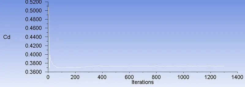
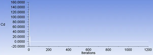
Based on the Cd values obtained for different Y+ values, at 5 obtained nearest Experimental value.(0.33)
So, further Postprocessing results are reported here for Y+ = 5 i.e, first layer thickness = 0.0716483 mm
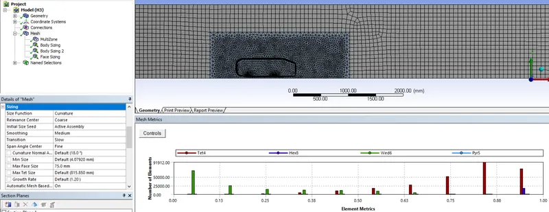
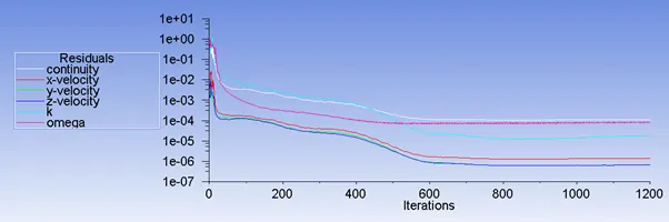
Results -
Vectors
Streamlines
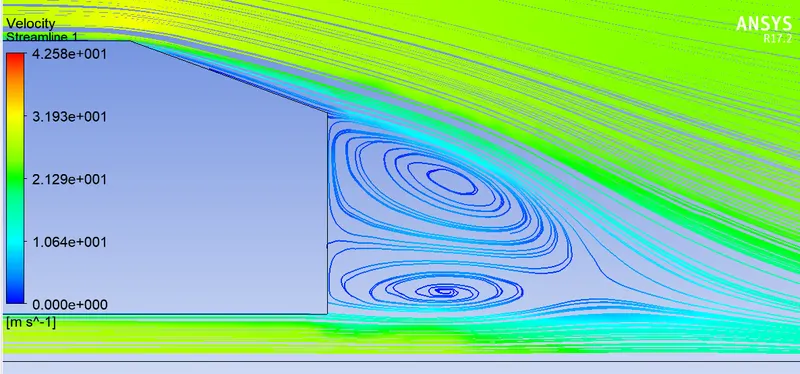
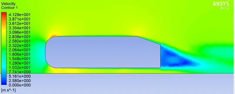
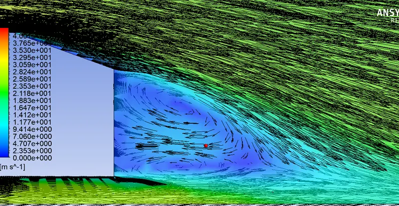
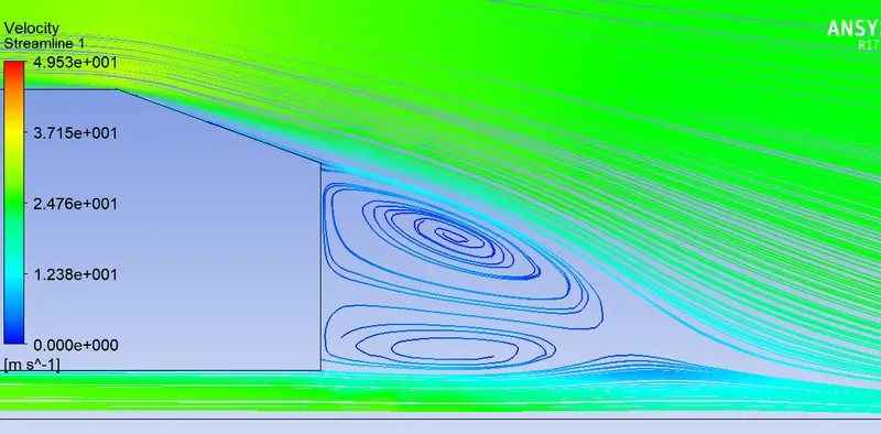
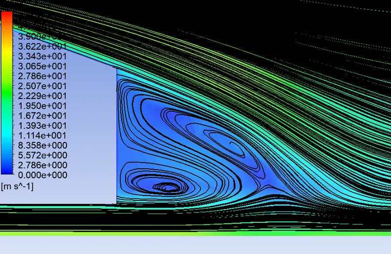
- We can clearly see from the steamline & vector contour of plane, the vortex formations.
- The shear layer rolls up from top & bottom edges into two recirculating flow regions, situated one over other.
- Such structures in the wake, which is the major separated flow region of a vehicle flow field, determine the drag experienced by the body.
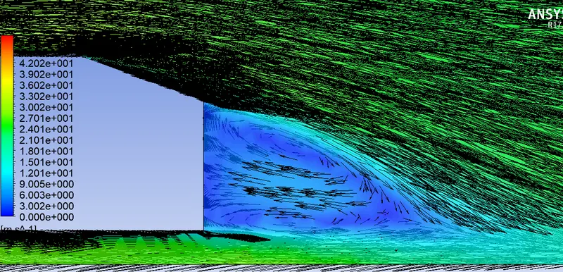
Case 2a : K-Epsilon Realizable model - Refined Mesh Y+35
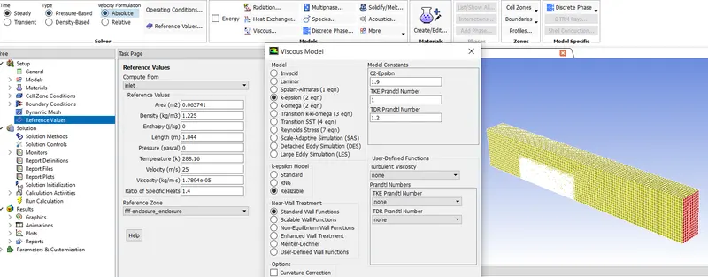
- K-epsilon an Hight Re-model is also used as case to compare results & this will also result in good fluid mixing/wake rather than forces on wall.
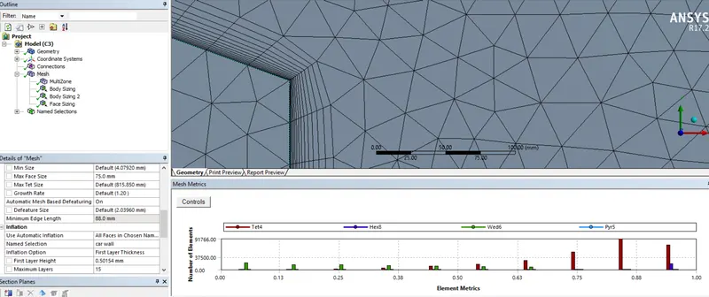
- Wall functions are used to bridge the inner region between the wall and the turbulence fully developed region. When using the wall functions approach, there is no need to resolve the boundary layer causing a significant reduction of the mesh size and thus computational domain.
- Here 30 < y+ < 300 (If this is too low, the model is invalid. If this is too high, the wall is not properly resolved)
Mesh -
Setup -
Results -
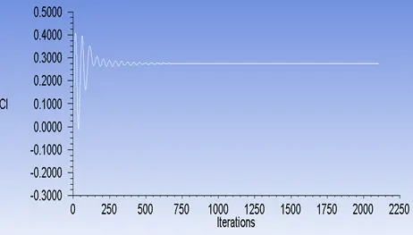
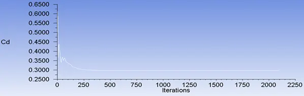
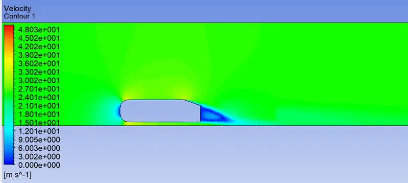
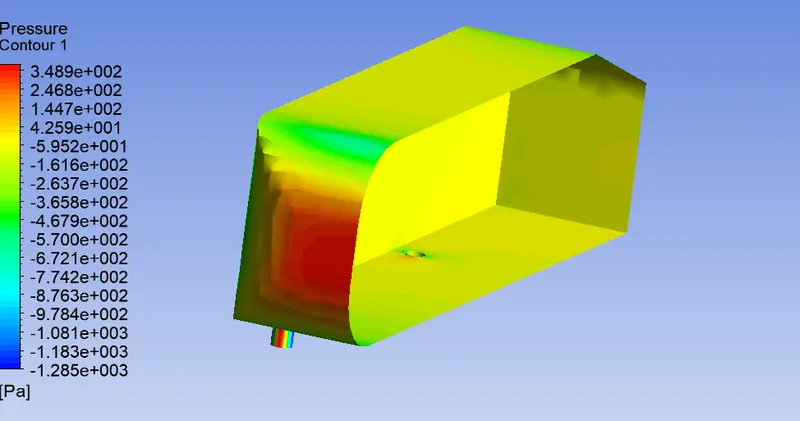
Vectors
Streamlines
Case 2b : K-Epsilon Realizable model - Refined Mesh Y+280
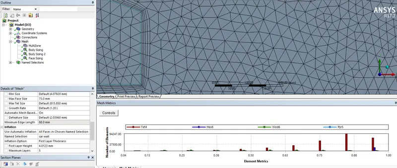
Mesh -
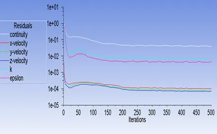
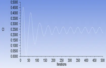
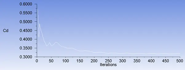
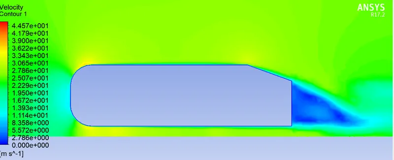
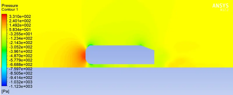
Results -
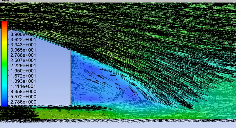
Vectors
Streamlines
Negative pressure in the wake region ? (Explanation is with respect to Ahmed body)
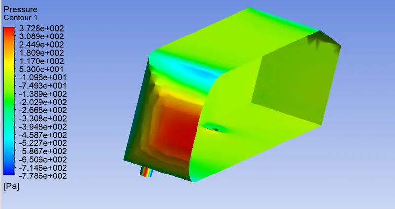
The air becomes almost stagnant as it strikes the vehicle, which results in air exerting very high pressure on front side of the Ahmed body (represented by the red area in pressure contours) Then airflow gets divided b/w the upper and lower surface of the vehicle. The high pressure air on front surface accelerates as it travels over the curved surface of Ahmed body, causing the pressure to drop. As the air continues to flow and make its way to the rear, a notch is created by the rear slant owing to flow separation, leaving a vacuum or low pressure space which the air is not able to fill properly.
This resulting lower pressure creates lift that then acts upon the surface area of the rear slant and roof surrface when it passed over.
Significance of the point of separation ?
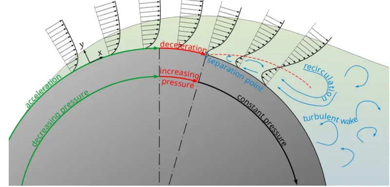
When the flow get seperated the effective cross-section of the flow increases, as the cylinder cross-section decreases.Then flow slows down and the static pressure rises again in the x-direction to finally reach the level of the atmosphere (∂p/∂x>0). This pressure gradient acting against the actual direction of flow is called adverse pressure gradient.
Depending on the shape of the body, the resulting adverse pressure gradient can become very large due to the decrease in speed and the boundary layer thickness increases significantly causing flow reverse and the laminar flow detaches itself from the contour at this point. A so-called turbulent wake is formed behind the body.
From a mathematical point of view, flow separation begins at that point on the surface where the flow is pushed back so strongly that the velocity gradient in the y-direction becomes zero (there is now a inflection point in the velocity profile). According to 'Newtons law of viscosity', this means that the shear stress at the wall, the so-called wall shear stress `(tau)` also becomes zero.
The separation of the boundary layer reduces the skin friction drag, but the pressure drag increases much more, so that the overall drag significantly.
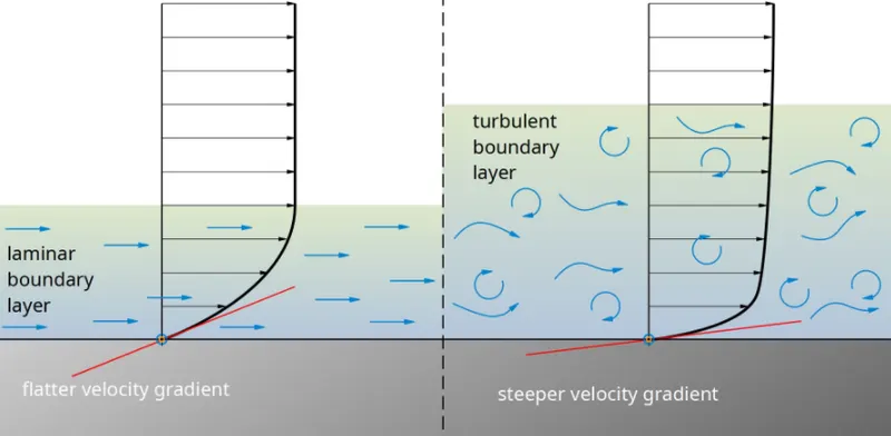
In the case of a turbulent boundary layer,larger velocity gradient near the wall are formed and thus higher velocity components in the boundary layer. The resulting higher kinetic energy of the boundary layer can counteract the adverse pressure gradient more,the separation point thus shifts downstream.The turbulent wake becomes narrower with the shifting of the separation point. This reduces the flow losses and thus the pressure drag, which ultimately results in a reduction of the overall drag.
Grid independency test -
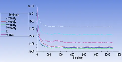
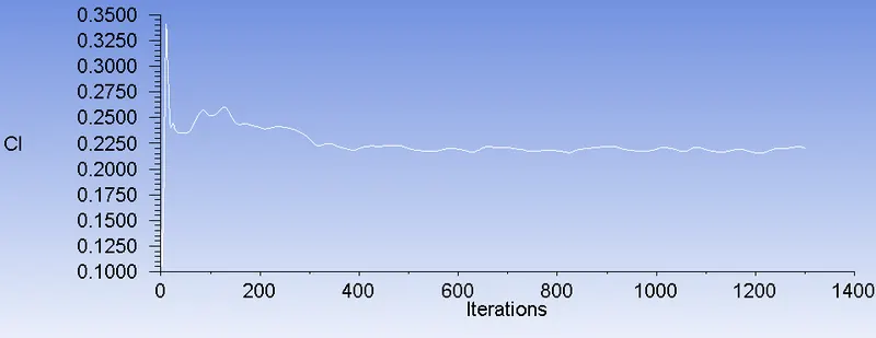
K-omga SST model of Y+5 : case 1b is used for the mesh independency study.
| Element Size (mm) | No. of Inflation layers |
Quality | |||||||
| Case | No of Elements |
Outer Encloure | Inner Encloure | Pillars face size |
Minimum Orthogonal |
Aspect ratio | Cd | Cl | |
| 1 | 427776 | 75 | 30 | 3 | 25 | 5.36E-03 | 3.65E+03 | 0.32963473 | 0.2666618 |
| 2 | 543237 | 75 | 25 | 3 | 5 | 1.33E-02 | 1.38E+03 | 0.29127455 | 0.20126193 |
| 3 | 2114294 | 75 | 15 | 3 | 10 | 2.41E-02 | 8.66E+02 | 0.29686548 | 0.17136128 |
| 4 | 201888 | 100 | 50 | 3 | 25 | 1.43E-03 | 8.08E+03 | 0.36006837 | 0.24696314 |
| 5 | 106483 | 150 | 40 | 5 | 10 | 1.43E-03 | 8.08E+03 | 0.35616172 | 0.20787804 |
- By selecting Fine & coarse mesh combination a different Cd values are obatined with around 10% Error.