Week 3 - External flow simulation over an Ahmed body.
Q1. Describe Ahmed's body and its importance.
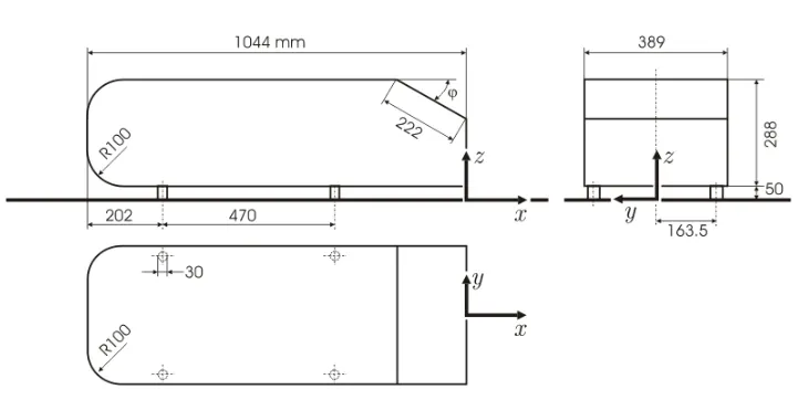
The Ahmed body is a generic car model first proposed by Ahmed et al (1984). All ground vehicles can be termed as bluff bodies moving close to the road surface, in which case they can be simplified as then Ahmed body. The external aerodynamics of the car defines many major traits of an automobile like stability, comfort and fuel consumption at high speeds. The flow around the vehicle is characterized by high turbulent and three dimensional flow separations as well as there is a growing need for more insight into the physical features of these dynamical flows. Since a lot of experimental and numerical test data is available on the ahmed body from published literature, it can be conveniently used as an universal benchmark for comparing new automobile designs and validating their data in CFD. Below provided are the dimenions of the Ahmed body [1].
Q2. Explain the reason for the negative pressure in the wake region.
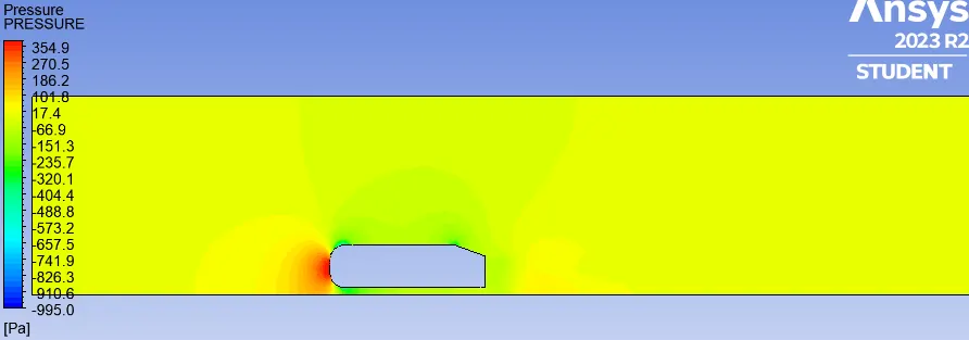
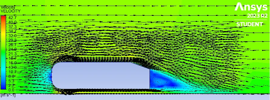
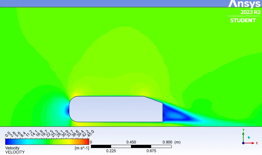
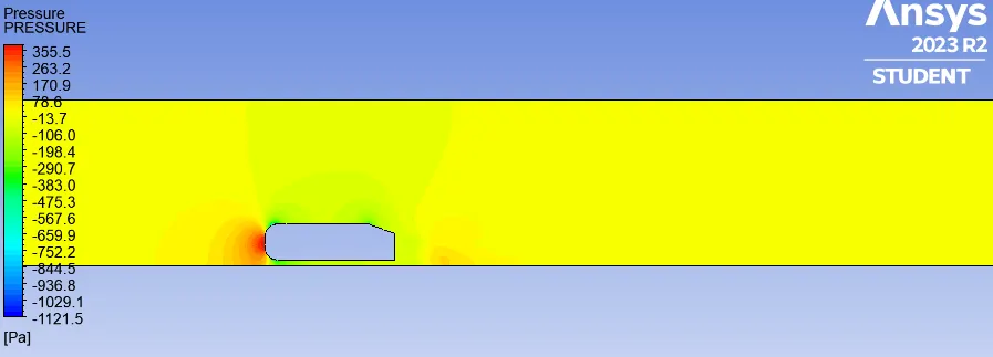
The flow behind an object separates from the surface and creates a highly turbulent region behind the object, called the wake. The wake behind the car is influenced by the flow around the car. The pressure inside the wake region remains low as the flow separates and a net pressure force (pressure drag) is produced. In other words, due to the production of pressure drag being produced from flow separation, the pressure in the wake region is low. This creates negative gauge pressure.
Q3. Explain the significance of the point of separation.
Pressure gradient is an is one of the factors that influences a flow immensely. A negative pressure gradient is termed a Favourable pressure gradient. Such a gradient enables the flow. A positive pressure gradient has the opposite effect and is termed the Adverse Pressure Gradient. Fluid might find it difficult to negotiate an adverse pressure gradient.
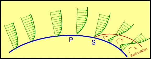
Figure: Separation of flow over a curved surface
One of the severe effects of an adverse pressure gradient is to separate the flow. As shown in above figure, the geometry of the surface is such that we have a favourable gradient in pressure to start with and up to a point P. The negative pressure gradient will counteract the retarding effect of the shear stress (which is due to viscosity) in the boundary layer. For the geometry considered we have a an adverse pressure gradient downstream of P.
Now the adverse pressure gradient begins to retard. This effect is felt more strongly in the regions close to the wall where the momentum is lower than in the regions near the free stream. As indicated in the figure, the velocity near the wall reduces and the boundary layer thickens. A continuous retardation of flow brings the wall shear stress at the point S on the wall to zero. From this point onwards the shear stress becomes negative and the flow reverses and a region of recirculating flow develops. The flow no longer follows the contour of the body, hence, we say that the flow has separated. The point S where the shear stress is zero is called the Point of Separation.
Depending on the flow conditions the recirculating flow terminate and the flow may become reattached to the body, forming a separation bubble. There are a variety of factors that could influence this reattachment. The pressure gradient may become favourable due to body geometry. The other factor is that the flow initially laminar may undergo transition within the bubble and may become turbulent. A turbulent flow has more energy and momentum than a laminar flow. This can extinguish separation and the flow may reattach.
PREPROCESSING
Geometry
First the Ahmed body was imported in SpaceClaim. Then it was split into half using split body tool in SpaceClaim.
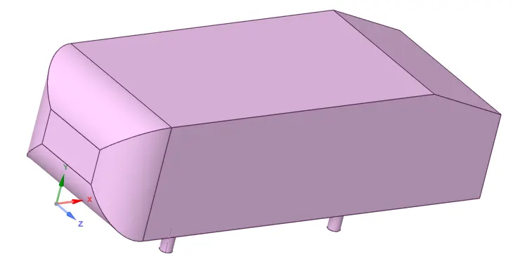
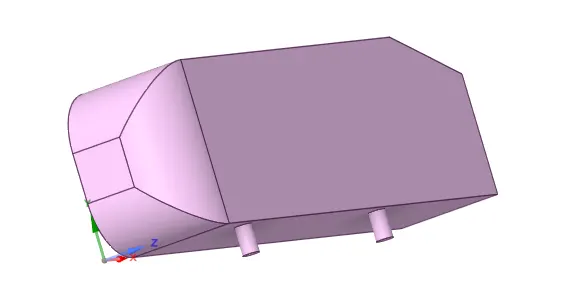
These planes were created to assist in the splitting of the body and checking for possible overlapping of bodies.
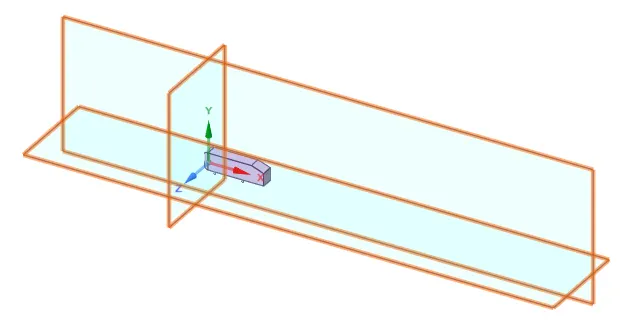
Two enclosures were created to materialise the wind tunnel. The inlet face of bigger enclosure is 2 meters from ahmed body front and the outlet face is 5 meters from ahmed body back.
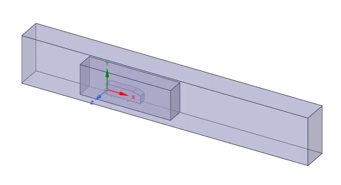
The smaller enclosure was created to obtain finer mesh near the ahmed body while keeping total number of mesh elements within computable limit of fluent solver operating on student license.
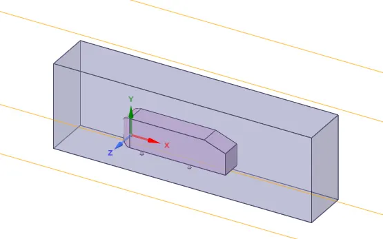
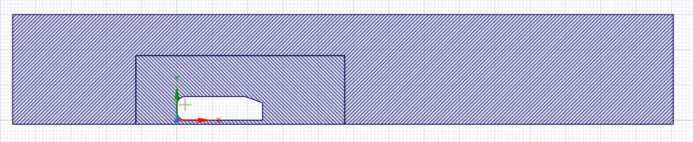
Overlaps created between 2 enclosure geometries were fixed using interference tool as is evident in below figure showing crossectional view of entire geometrical model.
Meshing
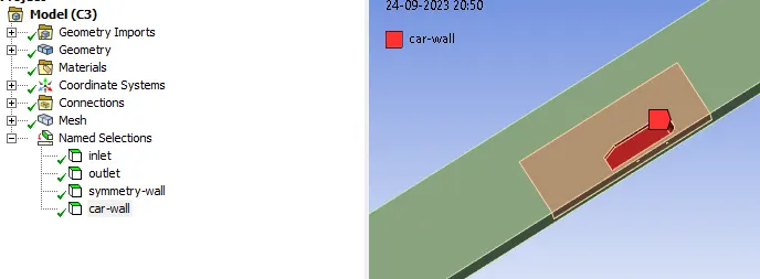
At first the named selections were provided for all relevant parts of geometry - inlet, outlet, symmetry wall and car wall.
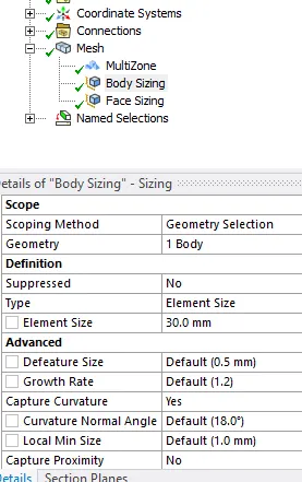
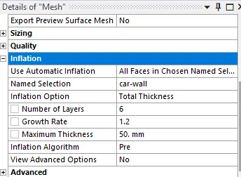
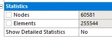
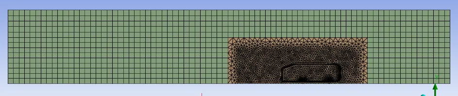
Mutizone meshing was added to make the majority of fluid volume hexa dominant mesh. Body sizing of 30 mm was given to create finer mesh inside the smaller enclosure. 6 inflation layers with a total thickness of 50 mm was provided to create a conforming mesh around the ahmed body. The obtained base mesh contains 0.25 million mesh elements which is well inside the limitation of student license. Moving ahead, this will be referred as the Base Mesh in this report.
Below 2 figures show the obtained mesh from -z axis.
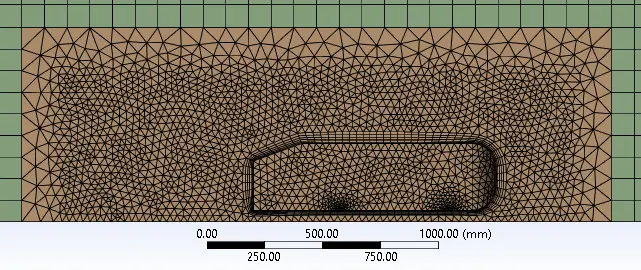
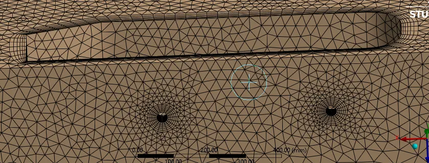
Face meshing with further small meshes was provided to capture the region around the legs of the ahmed body.
Solver
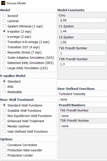
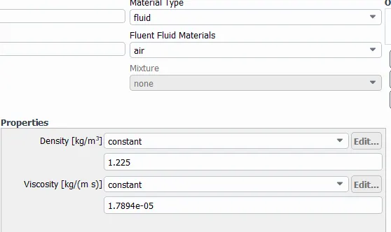
Pressure-based steady state solver was used to simulate the flow conditions. Energy equation was turned off since we're interested only in the flow patterns and Standard k-epsilon turbulence model was implemented to capture the physics of the flow. Air with its default properties as provided in fluent database was used as the fluid medium.
BOUNDARY CONDITIONS
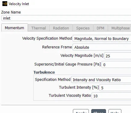
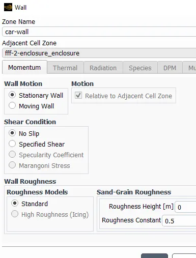
Inlet velocity of the flow was kept at 25 m/s. 0 Pa Gauge pressure at outlet and no-slip boundary condition at car-wall was ensured. Symmetry boundary condition was activated for other external walls of the flow.
Reference values were modified to suit the geometry and flow conditions properly.
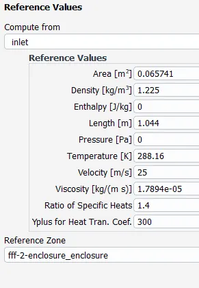
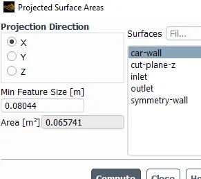
Length (1.044 m) of ahmed body was already known from Meile et al. [1] and area (0.065741 m2) was obtained from Projected Surface Area tool in fluent, as shown in figure above.
SIMPLE solution method was used since flow separation is a significant aspect of the simulation.
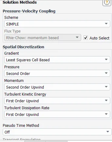
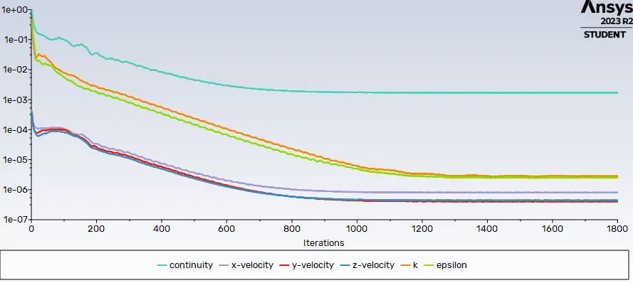
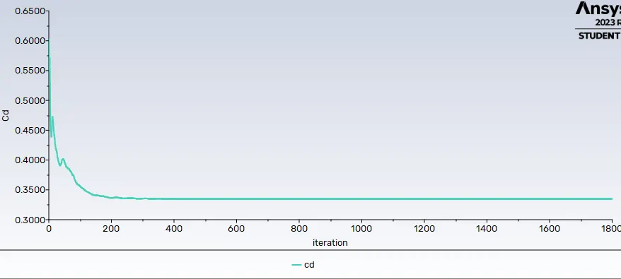
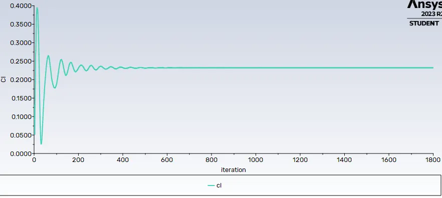
The setup was initialised using Hybrid initialisation and run for 1800 iterations. Below provided results were obtained using Base Mesh.
SCALED RESIDUALS
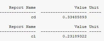
COEFFICIENT OF DRAG PLOT
COEFFICIENT OF LIFT PLOT
SOLUTION ANIMATION
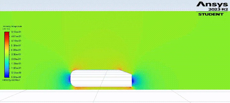
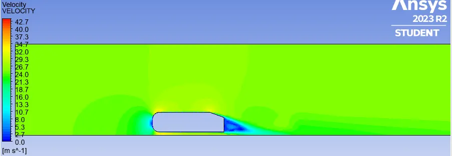
VELOCITY CONTOUR
PRESSURE CONTOUR
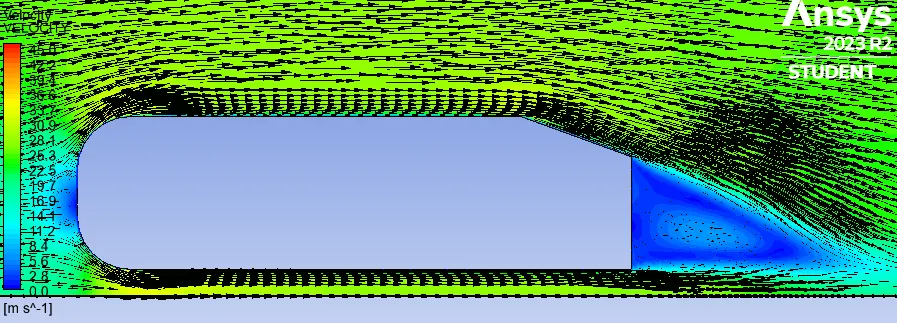
VELOCITY VECTORS
Similarly, a coarse mesh was created where the body sizing inside the small enclosure was given to be 40 mm. This resulted in a mesh with 0.13 million elements. The solver setup wasn't changed and after initialising hybridly, it was run for 1800 iterations. The drag and lift values have been provided later in the Grid Independency Test table.
FINE MESH SIMULATION
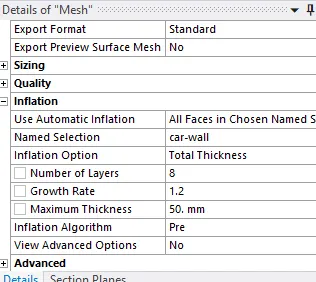
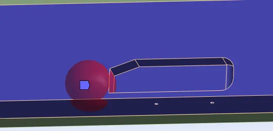
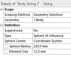
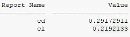
Finally, a fine mesh was created where the body sizing inside the small enclosure was given to be 25 mm. The no. of inflation layers were increased to 8 with a total thickness of 50 mm. Additionally a sphere of influence with 12 mm body sizing was added near the rear end of the ahmed body for better capturing of wake region flow vectors. All this resulted in a mesh with 0.58 million elements. The drag and lift values have been provided below in the form of snapshot as well as later in the Grid Independency Test table.
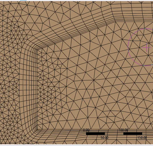
This is the fine mesh visual of small enclosure.
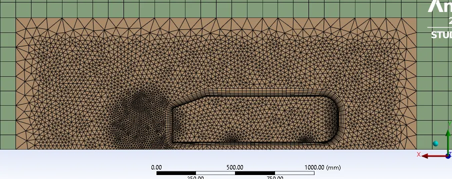
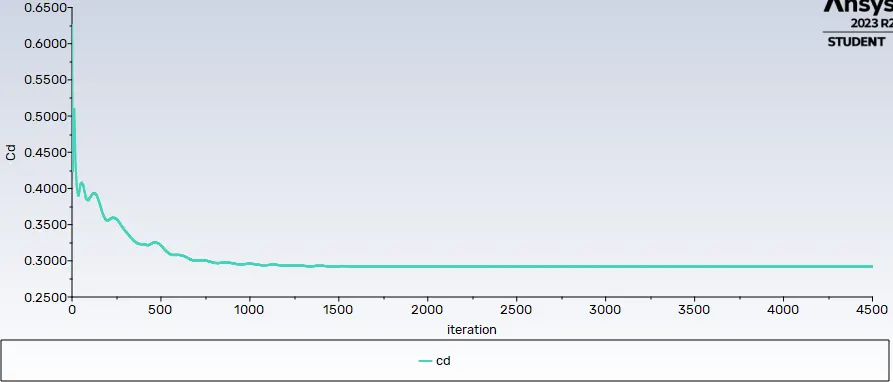
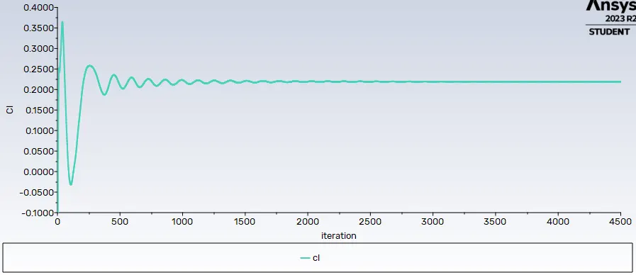
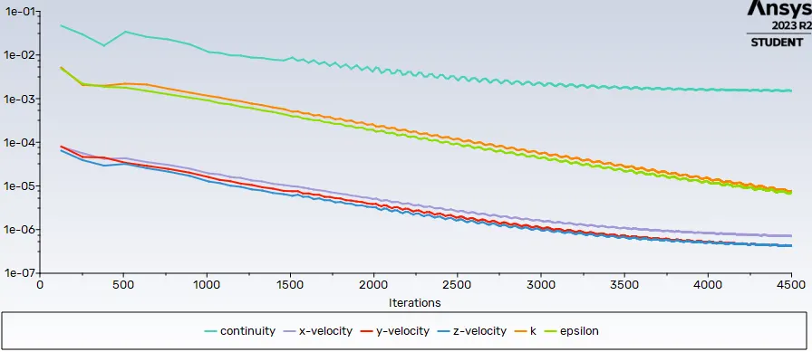
Keeping all solver setups same as in base mesh simulation, the solver was initialised using hybrid initialisation and run for 4500 iterations to obtain a converged result.
Below provided are the results obtained from Fine Mesh simulation of ahmed body.
COEFFICIENT OF DRAG PLOT
COEFFICIENT OF LIFT PLOT
SCALED RESIDUALS
SOLUTION ANIMATION
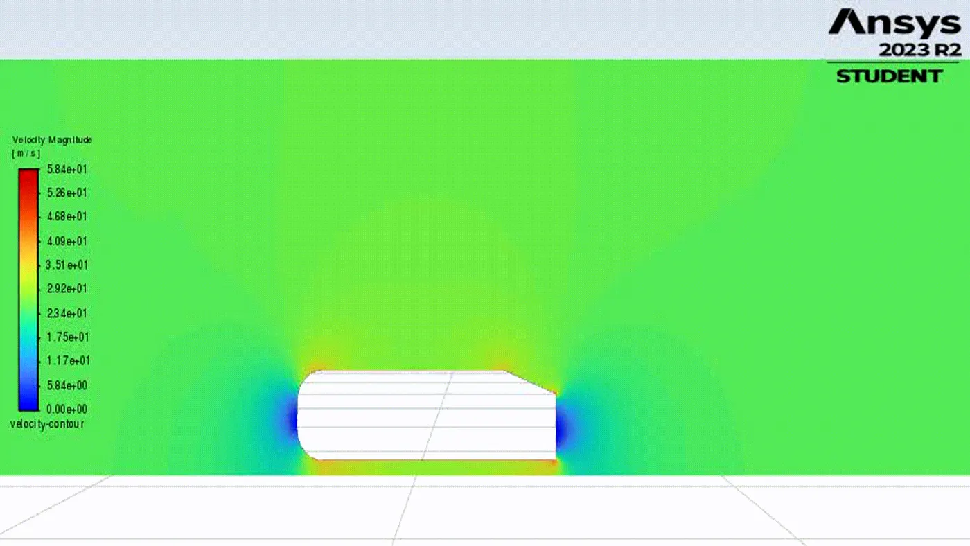
VELOCITY CONTOUR
PRESSURE CONTOUR
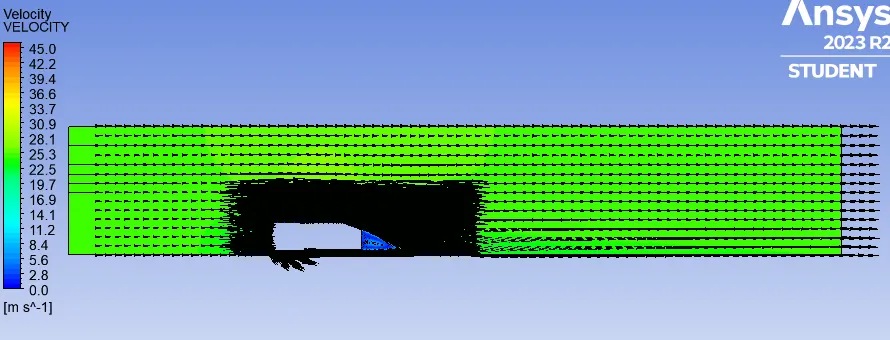
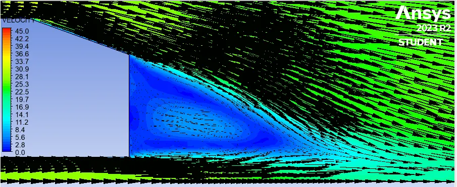
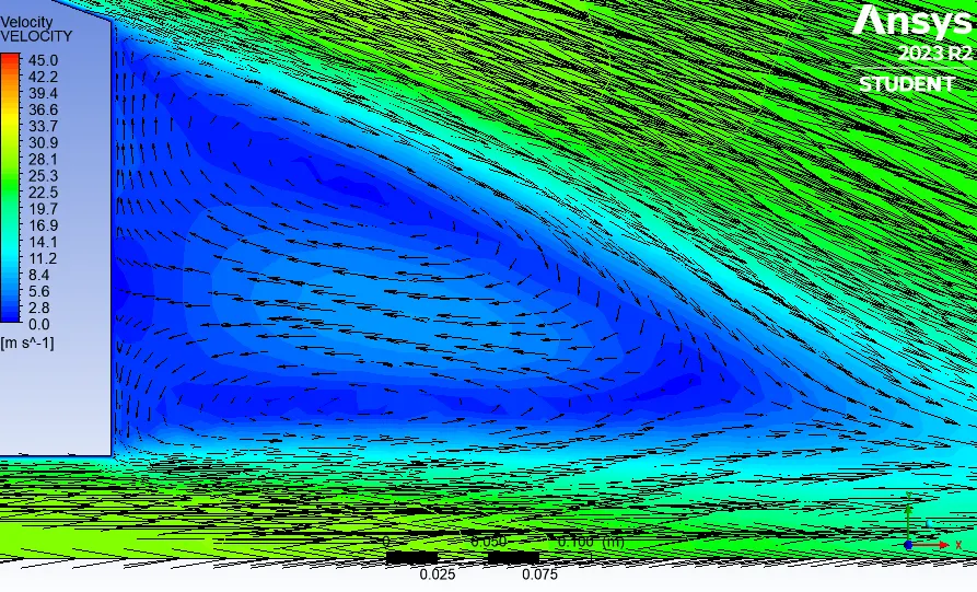
VELOCITY VECTORS
The following snapshots show how the velocity vectors look like when zoomed in progressively. In some places the vector symbol size has beed tweaked to provide clear visuals.
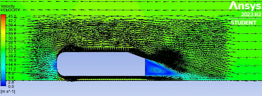
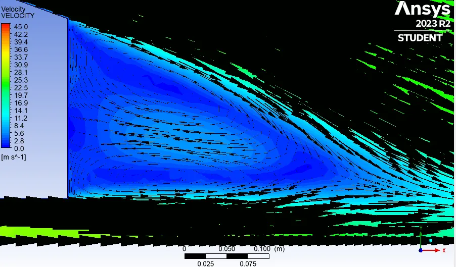
In the final visual, the vector symbol is changed from 3D arrow to Line arrow to clearly visualise the loops in wake region.
GRID INDEPENDENCY TEST
Below table shows the values of drag and lift of 3 different mesh types consolidated for comparision.
| Mesh type | Mesh Elements | Nodes | Drag (Cd) | Lift (Cl) |
| Coarse (40 mm) | 132713 | 38427 | 0.34980127 | 0.24088976 |
| Base (30 mm) | 255544 | 60581 | 0.33485893 | 0.23189322 |
| Fine (25 mm) | 582896 | 123717 | 0.29172911 | 0.2192133 |
CONCLUSIONS
- The wind-tunnel flow simulation with longitudinally split Ahmed body was performed and results obatained were satisfactory.
- For inlet velocity of 25 m/s the drag coefficients obtained were in the range of 0.29 to 0.34.
- Both drag coefficient and lift coefficient decreased progressively with thr refinement of mesh size.
- Well-formed wake regions were obtained for all cases.
- The inclusion of sphere of influence body sizing in fine mesh was very helpful in obtaining clear visual of negative wake region.
Reference
[1] Meile, W., Brenn, G., Reppenhagen, A., Lechner, B., & Fuchs, A. (2011). Experiments and numerical simulations on the aerodynamics of the Ahmed body. CFD letters, 3(1), 32-39.