Week 3 - External flow simulation over an Ahmed body.
AIM:
Simulate the flow over the Ahmed body and use air as the working fluid with velocity of 25 m/s.
Expected results:
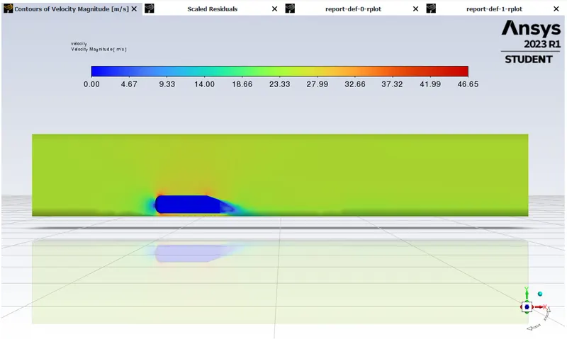
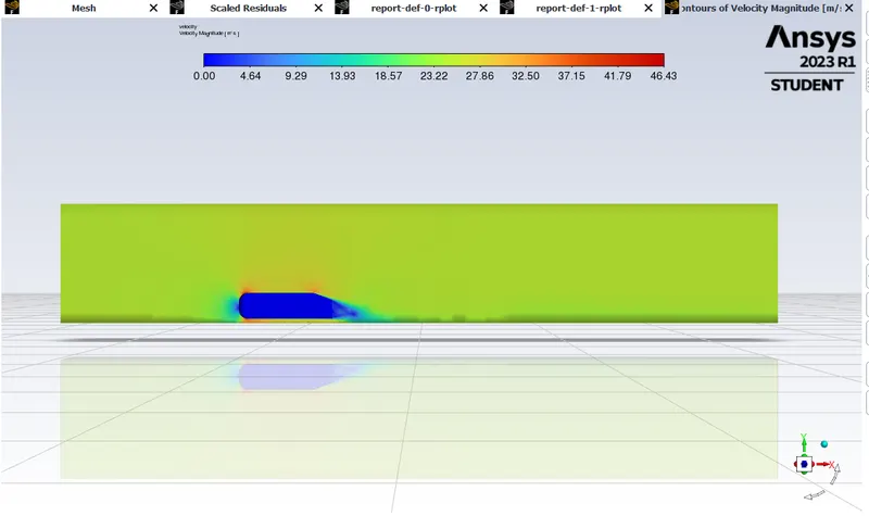
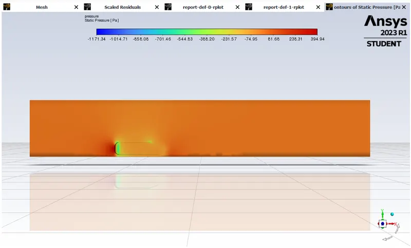
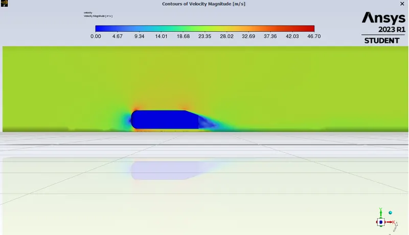
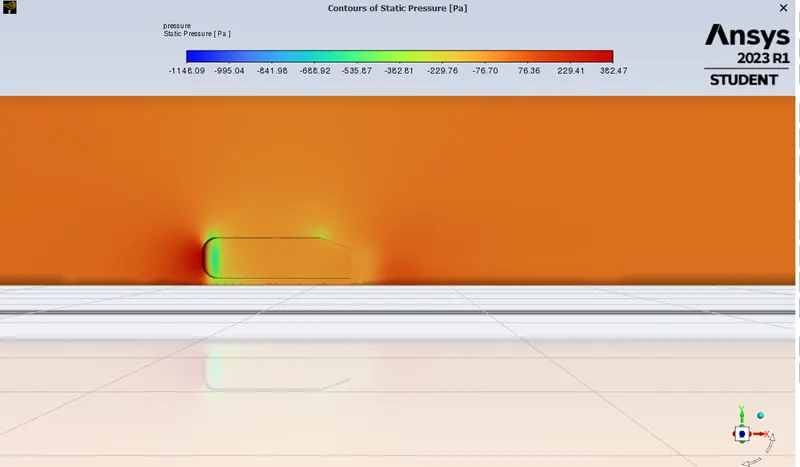
- Velocity and pressure contour.
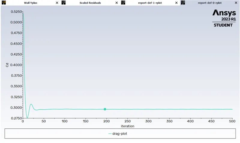
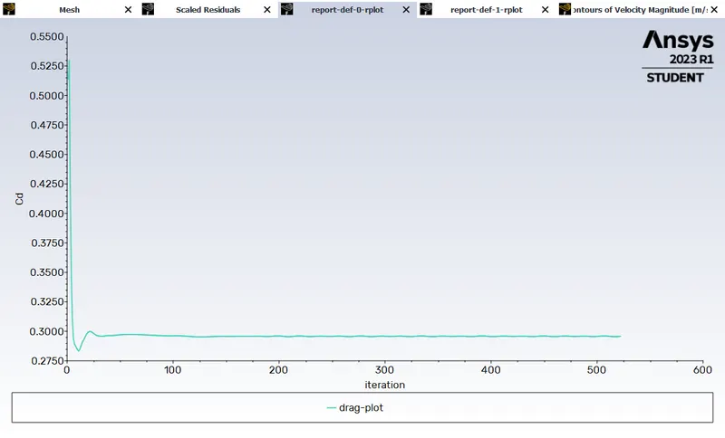
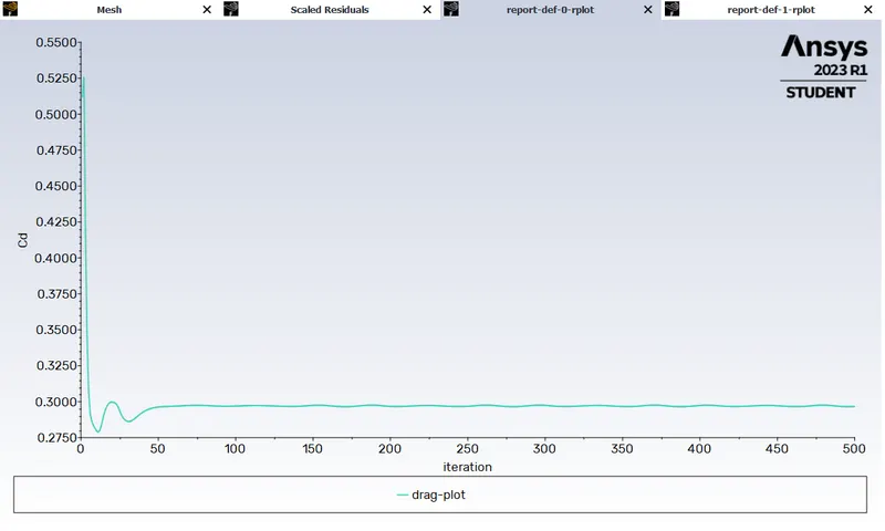
- The drag coefficient plot for a refined case.
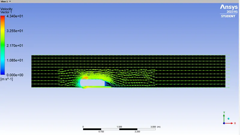
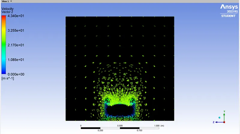
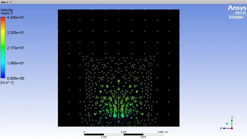
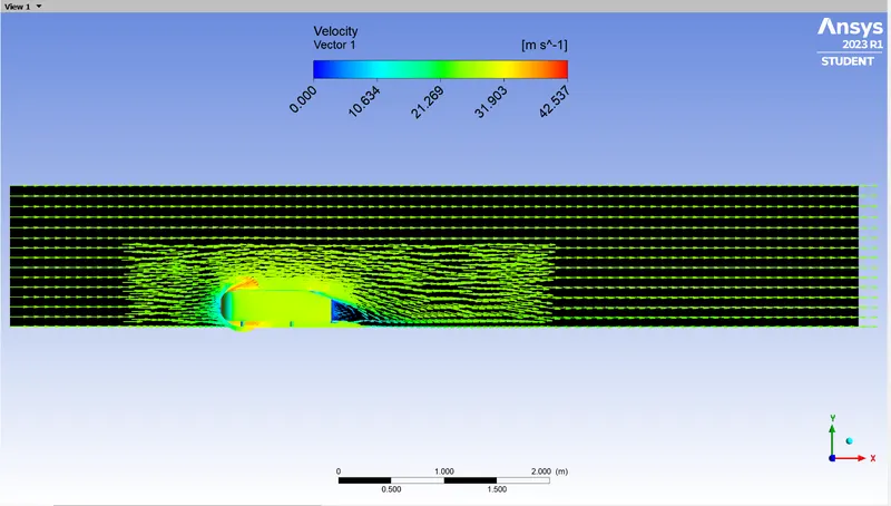
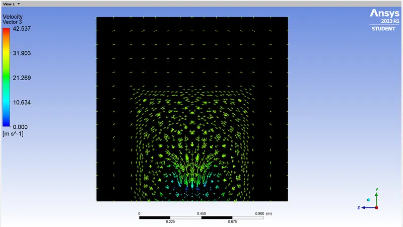
- The vector plot clearly showing the wake region.
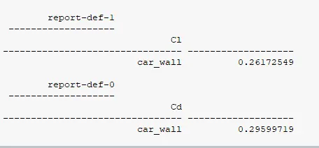
- Perform the grid independency test and provide the values of drag and lift with ease case.
INTRODUCTION:
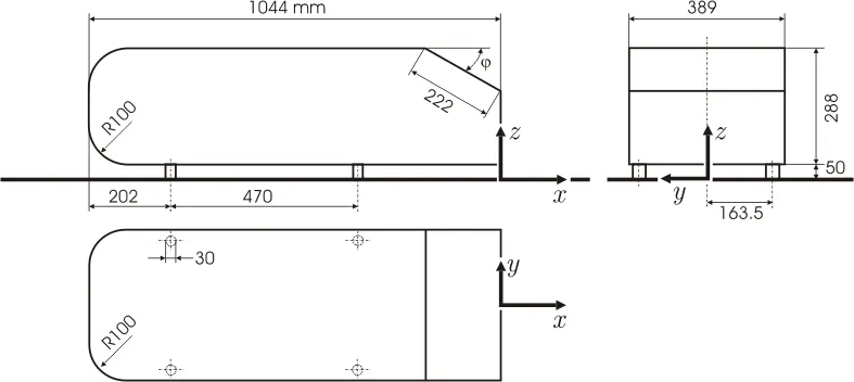
In Computational Fluid Dynamics (CFD), Ahmed's body is a widely studied and recognized benchmark for evaluating the performance of CFD codes in predicting the aerodynamic behavior of bluff bodies. The body is a simplified model of a car, consisting of a rectangular base, a slanted rear section, and two vertical end plates at the rear.
The Geometric figure of Ahmed Body is shown below:
THEORY:
- Importance of Ahmed's body.
Ahmed's body is important in CFD because it provides a standard test case for evaluating the accuracy and reliability of numerical simulations of fluid flow over bluff bodies. The body's geometry and flow conditions have been extensively studied experimentally, making it a well-understood benchmark for CFD validation. Ahmed's body is used to investigate various aspects of fluid flow over bluff bodies, such as the onset of turbulence, separation, and reattachment of flow, and the effects of different flow conditions and turbulence models. The accurate prediction of these flow phenomena is crucial in many engineering applications, such as automotive design, wind engineering, and aerospace engineering.
- The reason for the negative pressure in the wake region.
The wake is the region of turbulence that forms behind an object moving through a fluid, such as air or water. One of the key features of the wake is the presence of a negative pressure region. The negative pressure in the wake region can be explained by Bernoulli's principle, which states that as the velocity of a fluid increases, its pressure decreases. As the object moves through the fluid, it creates a disturbance in the flow, which causes the fluid to accelerate and increase in velocity. This increase in velocity results in a decrease in pressure, which leads to the formation of a region of low pressure in the wake. The vortices that form in the wake region also contribute to the negative pressure. These vortices are generated by the interaction between the fluid and the object as it moves through it, and they create a swirling motion in the fluid. This swirling motion also causes a decrease in pressure, which contributes to the overall negative pressure in the wake region.
The negative pressure in the wake region can have significant effects on the performance of the object moving through the fluid, such as increasing drag and reducing efficiency. It is therefore an important factor to consider in the design of aerodynamic structures.
- Significance of Point of separation.
The point of separation is the location on a solid object where the flow of fluid separates from the surface of the object and becomes turbulent. Understanding the significance of the point of separation is important in the design of aerodynamic structures. The point of separation is significant because it marks the transition from laminar flow to turbulent flow. Laminar flow is smooth and regular, while turbulent flow is chaotic and unsteady. When the flow separates from the surface of an object, it creates a wake of turbulent flow behind the object. This turbulent wake generates drag, which can slow down or destabilize the object and reduce its efficiency. the significance of the point of separation lies in its ability to predict and control the transition from laminar to turbulent flow, which affects the drag and lift forces experienced by objects moving through a fluid.
SOLVING AND MODELLING APPROACH:
In this simulation, air is taken as the working fluid and is flowed over a Ahmed Body with a velocity of 25 m/s. K-omega SST, RANS based solver is used for performing the simulation.
PRE- PROCESSING AND SOLVER SETTING:
Geometry:
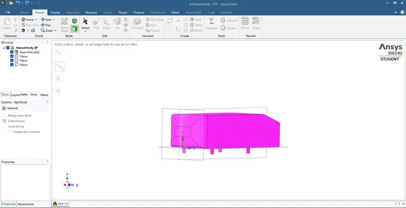
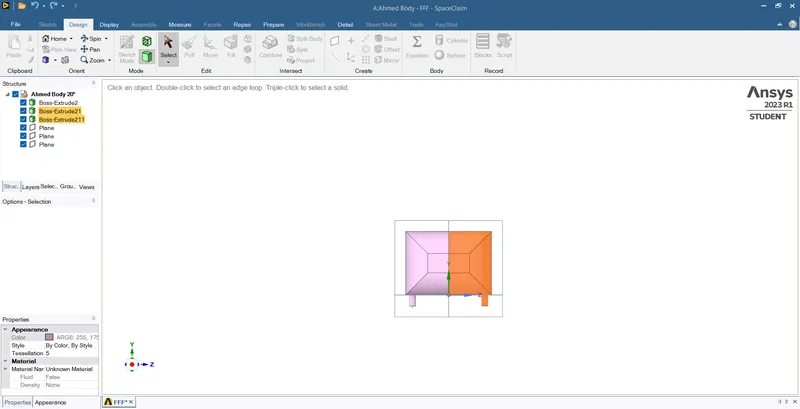
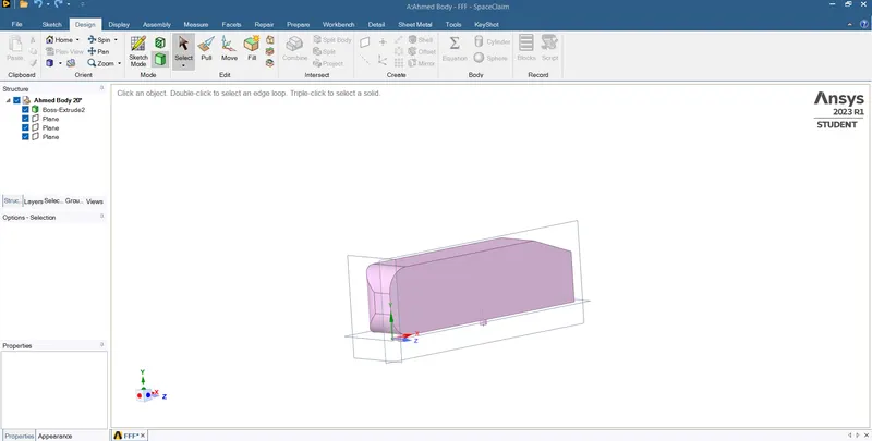
- Run ANSYS 2023 R1 student version and drag Fluid Flow (Fluent) in the project Schematic and then run ANSYS Space Claim by selecting it from Geometry. Then import the Ahmed's Body by using the option File> Open>Ahmed Body20.STEP. Create planes along the respectives axes by selecting the origin. Then using the split body option, split the Ahmed Body along the Y-axis plane by selecting the cut tool, and then delete the other half of the body.
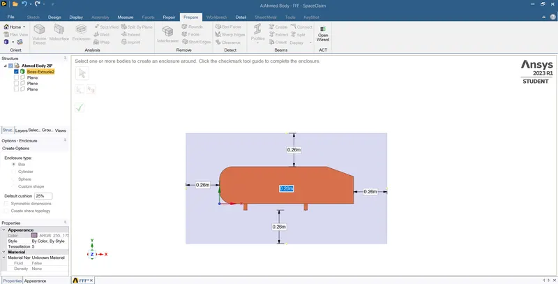
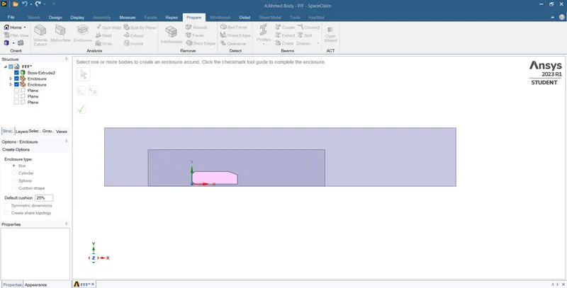
- Select Prepare>Enclosure options for creating enclosure over the Ahmed body to see the vortex and wake formation behind the Ahmed body. The dimensions for the enclosure are: For Front end- 2 m, Rear end- 5 m, Bottom end - 0 m, Top end - 1 m, Side to car wall - 0.5 m, Side to symmetric side - 0 m. Distances are taken from the car wall of all sides.
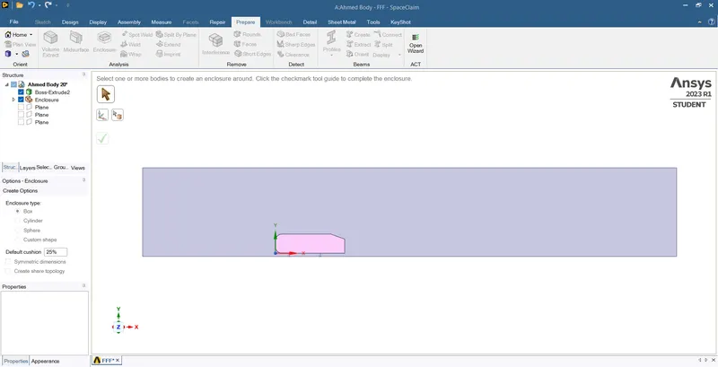
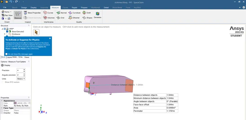
- Measure tool is used to check the various dimensions and other geometric datas as necessary for the body.
- Create another enclosure smaller than the previous enclosure by using the previous steps, so that the mesh near the car wall can be refined more. The dimensions of the smaller enclosure is shown in the figure below:
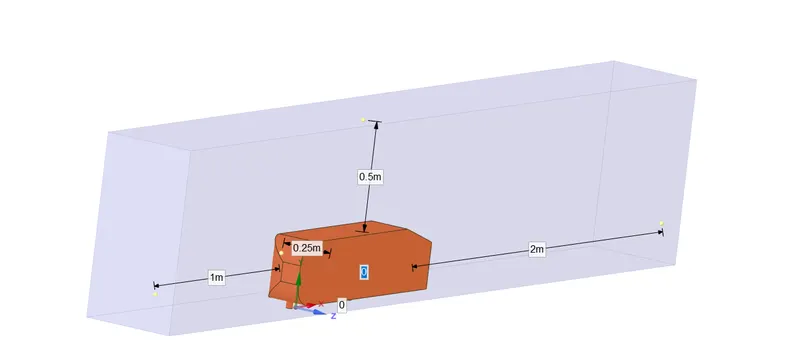
- Figure of both the enclosures is shown below:
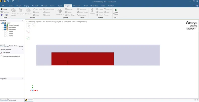
- Share the topology between the two enclosures, so that both the enclosure have same fluid flow, delete the interference between them by using the option Prepare> Interference. The software will atomatically detect the interference part, then click ok to delete it.
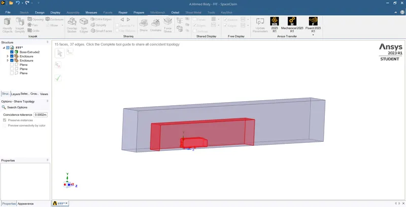
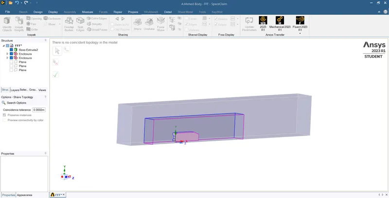
- The topology between two enclosures is shared, as it can be seen in the figure below:
Mesh:
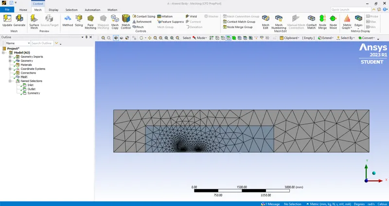
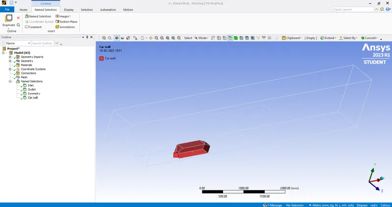
- Generate a coarse mesh after loading the Ahmed Body in the meshing window. Then name the different sections of the geometric body such as inlet, outlet, symmetry and car wall by selecting the appropriate body/sides by using the named selection option or by clicking 'N" after selecting the side.
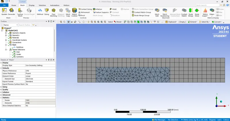
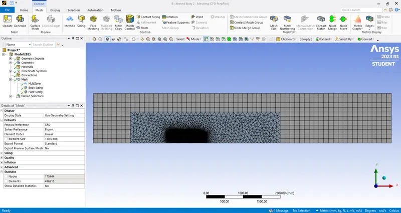
- Create Multizone mesh for the larger enclosure by selecting right click on mesh option and then selecting Insert>Method option, then selecting the appropriate body and element size as necessary and multizone method and then generating the mesh.
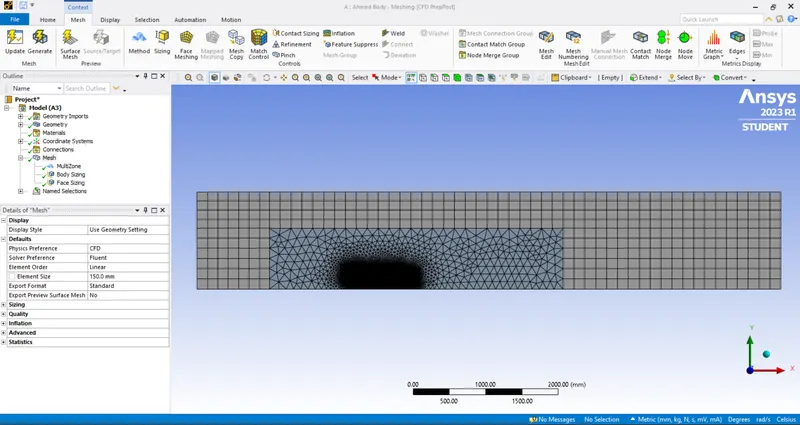
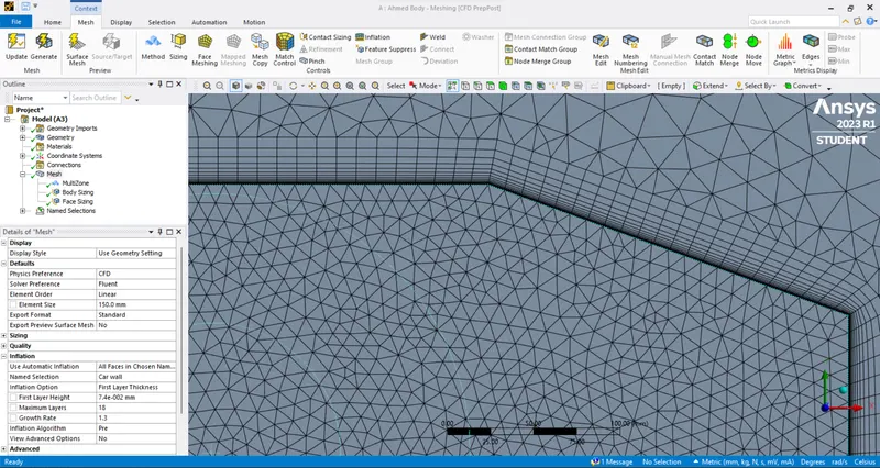
- Create Body sizing mesh for the smaller enclosure and face sizing mesh for the car wall by selecting the appropriate body. Select Mesh>Insert>Sizing , then select appropriate body and element size as necessary and then generate mesh. Different types of meshing is done to capture the flow seperation at the wake region.
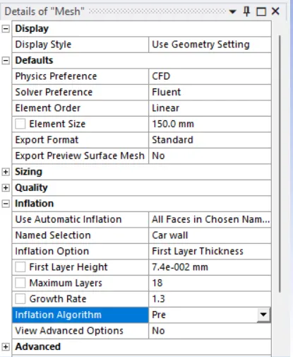
- To create an Inflation layer, calculate the first layer thickness by using Y+ Calculator by providing the appropriate values. The desired Y+ is taken as 5 for k-omega SST, growth rate is taken as 1.3, first layer height is taken as 0.000074. It is taken by comparing Prism Layer Total Thickness and Boundary Layer Thickness, where Prism Layer Total Thickness must be greater tan the Boundary Layer Thickness.
SETUP:
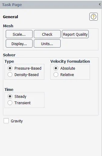
- Under general settings, selected pressure-Based type solver and steady time.
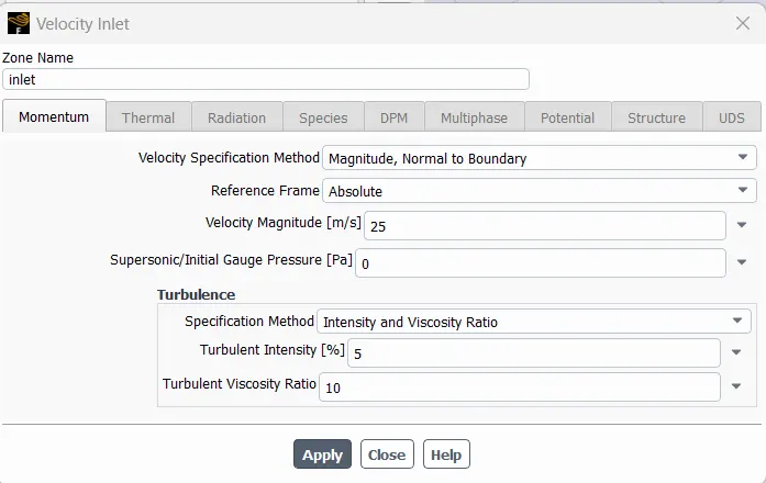
- Select Materials as air under fluid and set boundary conditions, where the inlet velocity will be 25 m/s.
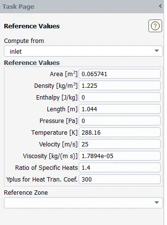
- Set reference values, area of the Ahmed Body can be calculated by using Projected Surface Areas option and then selecting the car wall.
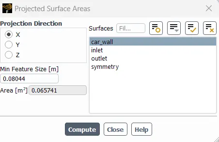
- The reference values of the setup is shown below:
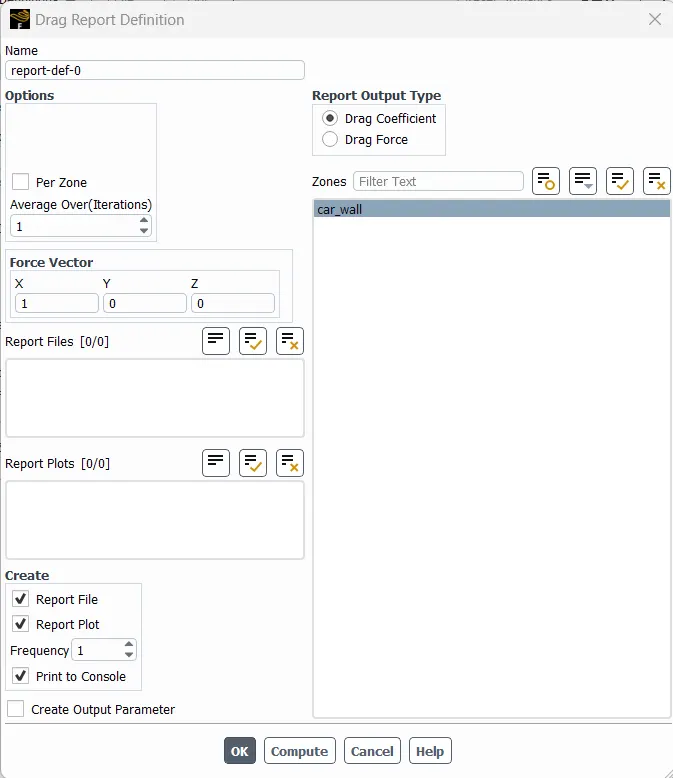
- Under solution tab, select Definitions> New> Force Report> Drag for drag coefficient, Definitions> New> Force Report> Lift for lift coefficient.
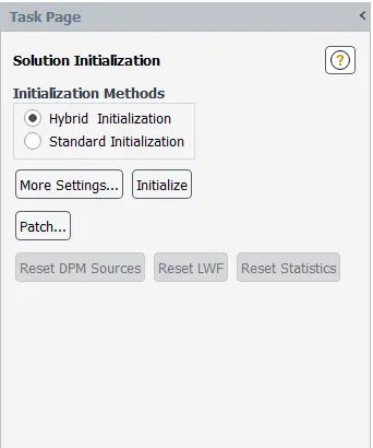
- For Initialization select Hybrid Initialization and then click initialize and then run necessary number of iterations until the solution is converged.
RESULTS:
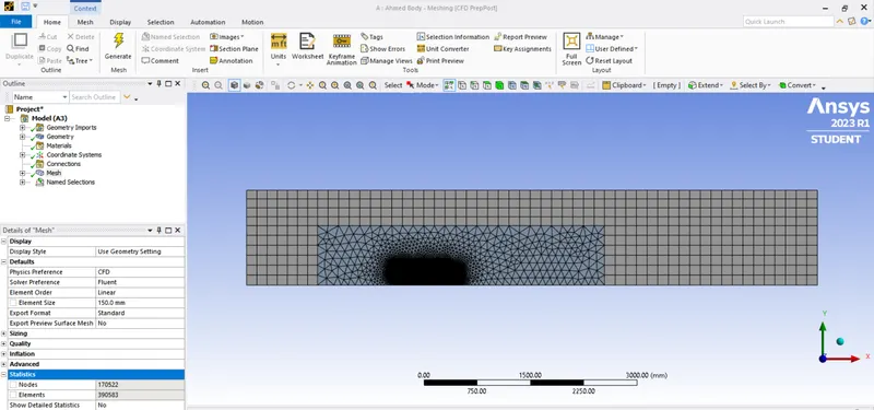
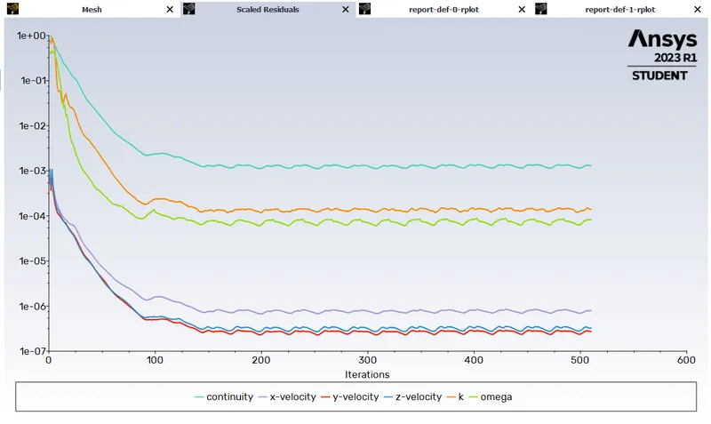
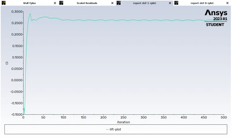
Case 1: Mesh sizes for Outer enclosure: 150 mm, Inner enclosure: 100 mm, Ahmed body: 10 mm
Mesh:
Scaled Residuals:
Drag Plot:
Lift Plot:
Velocity Contour:
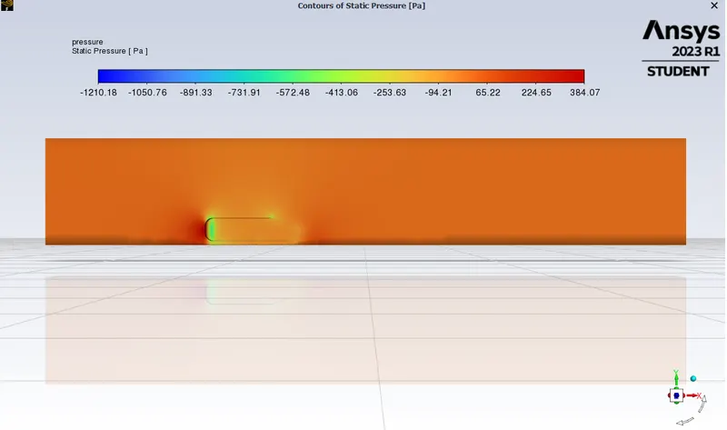
Pressure Contour:
Velocity Vectors:
Lift and Drag coefficient:
Case 2: Mesh sizes for Outer enclosure: 130 mm, Inner enclosure: 85 mm, Ahmed body: 10 mm
Mesh:
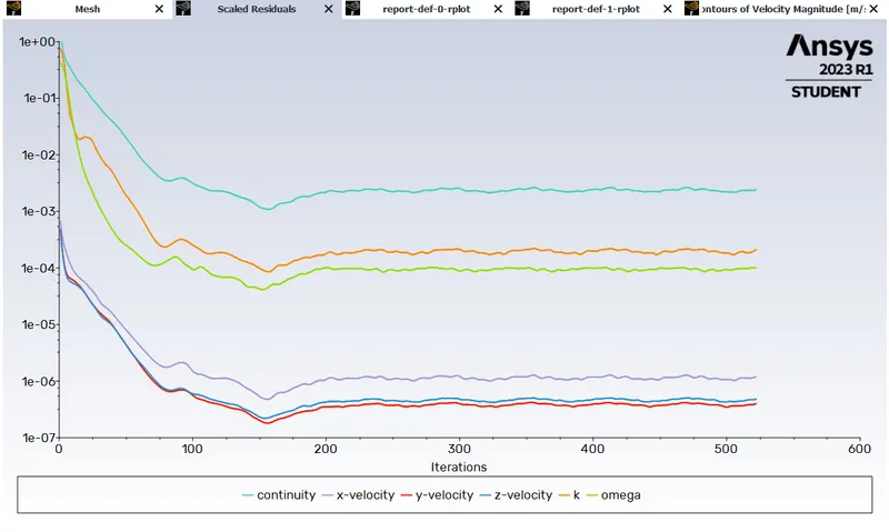
Scaled Residuals:
Drag Plot:
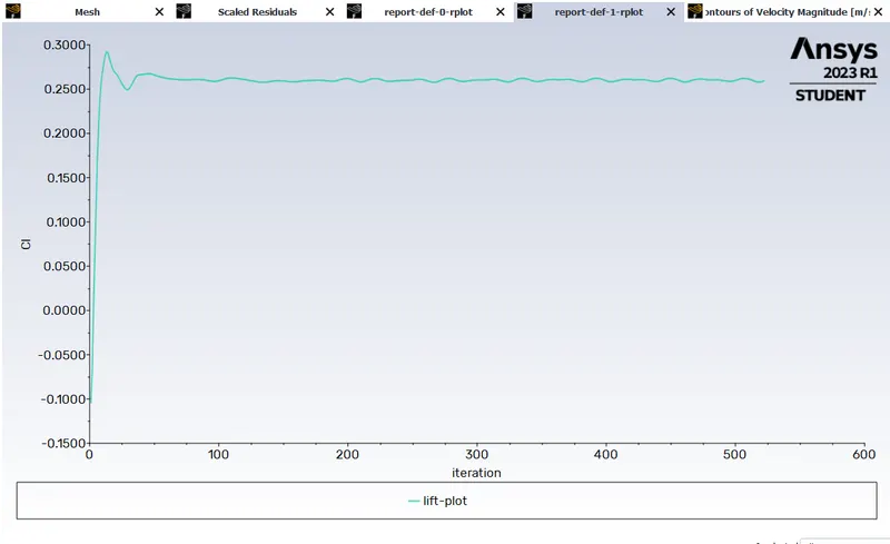
Lift Plot:
Velocity Contour:
Pressure Contour:
Velocity Vectors:
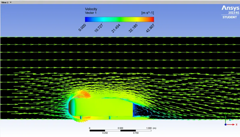
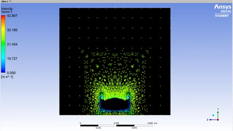
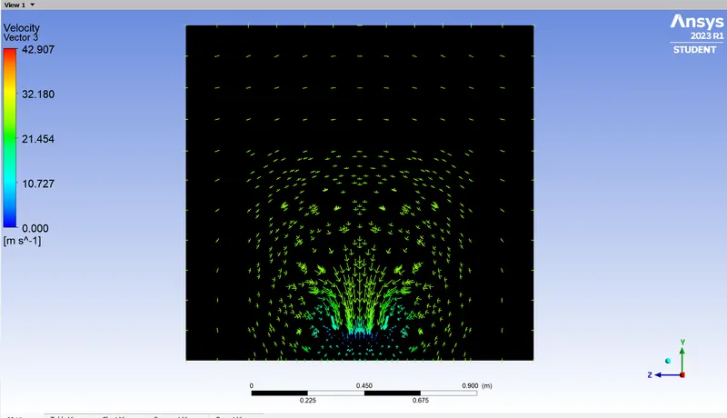
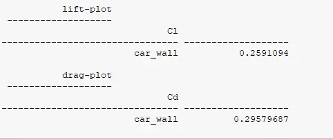
Lift and Drag coefficient:
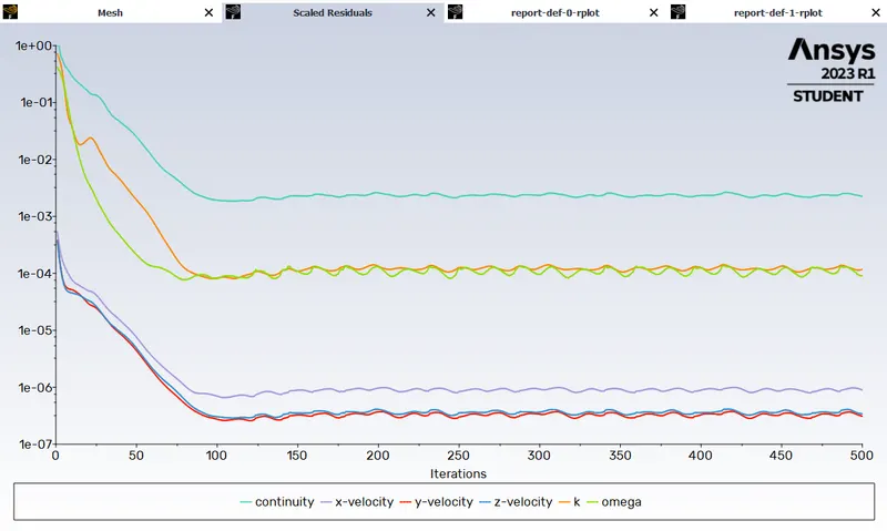
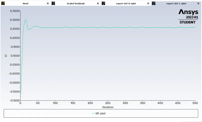
Case 3: Mesh sizes for Outer enclosure: 100 mm, Inner enclosure: 60 mm, Ahmed body: 10 mm
Mesh:
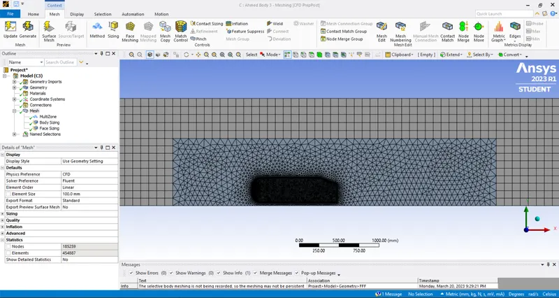
Scaled Residuals:
Drag Plot:
Lift Plot:
Velocity Contour:
Pressure Contour:
Velocity Vectors:

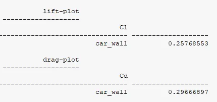
Lift and Drag coefficient:
CONCLUSION:
- High pressure is observed at the frontal end of the Ahmed Body due to loss of kinetic energy.
- Negative Pressure is observed at the rear end of the Ahmed Body due to flow separations which leads to higher velocity of the fluid as a result there's a decrease of pressure.
- As the mesh is more refined i.e more finer mesh with low element size, the drag and lift values are more accurate to experimental values.